GRL-PCIE5-CEM-RXA User Guide and MOI
Rev7.0
© Granite River Labs 2022 Version 7.0, June 2022. Updated 06.29.2022
Page 20 of 123
4.1
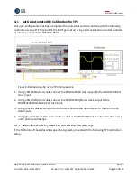
Set Up Automated Rx Calibration for TP3
Once pre-configuration has been completed from previous section, continue with the following
calibration setup at TP3 (output of the BERT generator) using a GRL automation control enabled
oscilloscope and Anritsu MP1900A BERT.
F
IGURE
8.
R
ECOMMENDED
S
ETUP FOR
TP3
R
X
C
ALIBRATION
1.
Using a SMA-SMA short cable, connect the MU181000A/B clock output to the MU181500B Ext
clock input.
2.
Using a SMA-SMA short cable, connect the MU181500B jittered clock output to the
MU195020A/MU196020A Ext clock input.
3.
Using coaxial cables, connect the MU195020A/MU196020A data outputs to the MU195050A
data inputs.
4.
Using phase matched K-K coaxial cables, connect the MU195050A data outputs to Channels 1
and 3 on the oscilloscope.
4.1.1
TP3 Calibration Setup with Tektronix ATI Based Oscilloscope
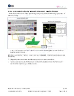
If the Tektronix ATI based oscilloscope is being used, proceed with the following TP3 calibration
setup.


