GRL-PCIE5-CEM-RXA User Guide and MOI
Rev7.0
© Granite River Labs 2022 Version 7.0, June 2022. Updated 06.29.2022
Page 23 of 123
4.2.1.1
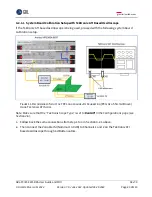
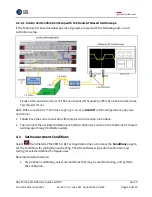
System Board Calibration Setup with Tektronix ATI Based Oscilloscope
If the Tektronix ATI based oscilloscope is being used, proceed with the following system board
calibration setup.
F
IGURE
11.
R
ECOMMENDED
S
ETUP FOR
TP2
L
ONG
C
HANNEL
R
X
C
ALIBRATION
(PCI
E
G
EN
5
S
YSTEM
B
OARD
)
U
SING
T
EKTRONIX
ATI
S
COPE
Note: Make sure that the “Tektronix Scope Type” is set to
Dual ATI
in the Configurations page (see
Section 4.6).
1.
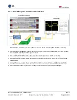
Follow back the same connections from step 1 to 4 in Section 4.2.1 above.
2.
Then connect the Variable ISI (Nominal 13.0 dB) to Channels 1 and 2 on the Tektronix ATI
based oscilloscope through 6 dB attenuators.

