38
TQ10 User Guide
Integral Gain
Integral gain provides a torque that is directly proportional to the sum, over time, of the
error signal—the
integral
of the error. If the error persists, integral gain provides a restoring
force that grows larger with time. Integral gain can remove steady state errors that are due
to gravity or a constant static torque. It can also correct velocity lag and following error in a
constant velocity system.
Too much integral gain can cause overshoot during acceleration and deceleration; this
overshoot will increase settling time. You should use only as much integral gain as your
application requires. If your application does not need any, you should disable it (see
below).
Integral Gain Disable
You can
permanently
disable integral gain by connecting a wire from the terminal labeled
I-GAIN OFF
to ground. Notice on the block diagram that even if you zero the integral gain
potentiometer, integral gain is not reduced to zero, just to a lower value. There will still be
integral gain in the system (because of voltage on resistor R
I
). The only way you can
eliminate integral gain is to ground
I-GAIN OFF
.
You can use a control signal to
temporarily
disable integral gain, by connecting
I-GAIN OFF
to ground only during acceleration and deceleration. This will disable integral
gain during those parts of the move, which should decrease overshoot and settling time.
When the system reaches constant velocity or comes to rest, use your control signal to
break the ground connection, which will re-enable integral gain.
Tuning Procedure
In the procedure given below, you will systematically vary the tuning potentiometers until
you achieve a move that meets your requirements for accuracy and response time.
You can adjust the potentiometers through three holes in the drive’s front cover. Use the
plastic adjustment tool supplied with the TQ10SD to make adjustments. Turn the
potentiometers clockwise to increase the gains.
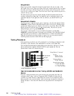
turn pot 12 turns
counterclockwise
turn pot clockwise
P:
I :
D:
3 turns clockwise
0 turns clockwise
4
1
/
2
turns clockwise
To Zero:
To Increase Gain:
Factory Default Settings:
Tuning Pots are 12 turn pots
4 FAULT OUT -
P
I
D
4
5
6
7
HALL GND
HALL +5V
HALL 1
HALL 2
Proportional
Integral
Derivative
Tuning Potentiometer Locations
Special Considerations when Tuning with SM and NeoMetric
Motors
If you use a high performance motor (peak current rating greater than three times the
continuous current rating), such as a Compumotor SM or NeoMetric Series motor, be
careful not to overheat the motor while tuning your system. If you accidentally choose
tuning gains that cause motor instability, excess motor current can quickly overheat and
damage the motor—even before the thermostat can trigger the motor overtemperature
circuit.
Artisan Technology Group - Quality Instrumentation ... Guaranteed | (888) 88-SOURCE | www.artisantg.com


