➁
Installation
29
Specifications for the step and direction inputs are as follows:
Step+/Step–
Specifications
Dir+/Dir–
Applied Voltage
5 V maximum
Input Current
12 mA maximum
6.3 mA minimum
Step Pulse
500 nsec minimum pulse width
Setup Time
Direction input may change polarity coincident
with the last step pulse. The direction input must
be stable for 500 nsec before the drive receives
the first step pulse.
You can use an input voltage higher than 5V if you install a resistor in series with the input,
to limit current to the range specified above.
Encoder Input Connections
You must connect an encoder to the TQ10SD’s encoder inputs. These are differential
inputs; therefore, your encoder should have differential outputs. Single-ended operation is
possible, but is more susceptible to electrical noise and is not recommended. Up to 200 mA
at 5 volts is available from the TQ10SD to power encoder electronics.
681
Ω
Internal Connections
B+
B-
26LS32
681
Ω
681
Ω
Internal Connections for CHA
and CHB are identical
MOTOR
Encoder
3 ENCODER GND
4 E5
5 ENCODER A+
6 ENCODER A–
7 ENCODER B+
8 ENCODER B–
Encoder Input Specifications:
• Maximum low input: 0.8V
• Minimum high input: 2.0V
• Maximum input frequency: 1 MHz
• A Leads B – CW Rotation
• B Leads A – CCW Rotation
TQ10SD
Motor
+5V
200mA max. at 5V available to
power encoder electronics
Encoder Input
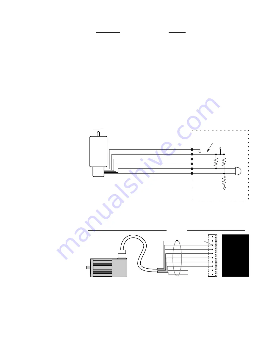
The color code for encoder wires is shown in the next drawing for Compumotor SM and
NeoMetric Series servo motors.
TQ10SD Torque Servo Drive
SM or NeoMetric Motor with TQ Cable
shield
Black
Red
White
Yellow
Green
Blue
Orange (nc)
Brown (nc)
Encoder
Cable
1
2
3
4
5
6
7
8
9
10
SH
SHUTDOWN -
ENCODER GND
E5
ENCODER A +
ENCODER A -
ENCODER B +
ENCODER B -
RESERVED
RESERVED
Connecting Encoder Input to SM or NeoMetric Motor Encoder Cable
The orange and brown wires connect to
INDEX+
and
INDEX-
on the encoder, which the
TQ10SD does not use. Do not connect these two wires to the drive.
Artisan Technology Group - Quality Instrumentation ... Guaranteed | (888) 88-SOURCE | www.artisantg.com


