36
TQ10 User Guide
Tuning Procedure with SM and NeoMetric Motors:
➀
Heatsink Your Motor:
This is especially important in temporary “bench top” procedures. SM
and NeoMetric Motors dissipate excess heat through their faceplate; to ensure proper motor
cooling, the faceplate must be mounted to a heatsink.
➁
Reduce Peak Current:
Using the drive’s DIP switches, set the peak current at a level that is
less than twice the motor’s continuous current rating: Following the dipswitch settings
illustrated on the back cover will do this.
•
4.4 amps for SM motors with
-A
windings
•
7.4 amps for SM motors with
-B
windings, N0921F
•
6.0 amps for N0701D and N0702E motors
•
8.9 amps for N0702F, N0701F, N0703F, N0704F
•
10.0 amps for N0703G, N0704G, N0921G, N0922G
➂
Select Tuning Gains:
Starting with low tuning gains (proportional gain at zero, or very low),
test your system’s response. Adjust the gains until you achieve a satisfactory response and
settling time. Use aggressive gains only when necessary; they are likely to cause the system to
become unstable. Before proceeding to the next step, ensure that the system is stable.
➃
Try Your Application’s Move:
To see if current and gain settings are adequate for your
system, try your actual move (rather than the test move). If the move is successful and your
motion requirements are satisfied, you do not need to increase peak current any higher—
tuning is complete. Proceed to
Step 7
below.
If the move is not successful, proceed to
Step 5
.
➄
Increase Peak Current:
Using the DIP switches, increase peak current to: 6.0 amps for SM
motors with A windings; 10.0 amps for all other motors. Do not exceed your motor’s peak
current rating, or three times its continuous current rating, whichever is lower.
➅
Repeat Steps 3, 4:
Continue repeating
Steps 3 – 4
until you achieve performance satisfactory
for your application. Use only enough peak current to satisfy your motion requirements—not
every application requires maximum peak current.
➆
Verify Thermal Stability:
Run your application for at least four thermal time constants to
ensure that the motor stabilizes at an acceptable temperature.
Example:
An SM232A motor’s current ratings are 2.1A continuous, 6.3A peak; its thermal
time constant is 35 minutes. The motor is to be used in an application that requires 95% peak
torque; required peak current is therefore (6.3A • 0.95) = 6A.
Step 1:
Start with peak current DIP switches set for 4.4A. Determine a set of initial tuning
gains that is stable. If at any time the system becomes unstable, disable the drive immediately.
Step 2:
Try the application’s move. If the application’s motion requirements are satisfied, go
to
Step 4
, below
Step 3:
If necessary, increase peak current to 6.0A and determine the final set of tuning gains.
Verify that the application’s motion requirements are satisfied.
Step 4:
Run the application for at least 4 thermal time constants (140 minutes) to ensure that
the motor stabilizes at an acceptable temperature.
Tuning – TQ10SD Step & Direction Drive
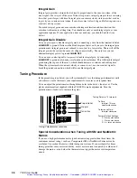
You must tune the TQ10SD’s internal
Proportional Integral Derivative
(PID) servo control
loop for optimum system performance. A properly tuned system will exhibit smooth motor
rotation, accurate tracking, and fast settling time.
Tuning Theory
The TQ10SD generates a move profile based upon step and direction signals from the
indexer. Incoming steps represent
commanded position
, and go to a summing node.
Incoming encoder counts represent
actual position
, and also go to the summing node.
During a typical move, actual position will differ from commanded position by at least a
few encoder counts. At the summing node, actual position is subtracted from commanded
position—the resulting difference is the
position error
, which is converted into an analog
voltage. This analog error signal is the input to the PID control loop, whose block diagram
is shown below.
Artisan Technology Group - Quality Instrumentation ... Guaranteed | (888) 88-SOURCE | www.artisantg.com

