Appendix A
63
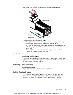
If you are unsure of which settings to use for your motor, start with the setting shown above
for the OEM3401 motor. If the motor gets hot when it is stopped, reduce the loop gain
setting (DIP SW2 — #4, #5, #6).
The DIP switch settings shown above will enable foldback—after approximately three
seconds at full current, the drive will fault due to foldback. These settings will help protect
your motor while you prototype your system. To disable the foldback fault, to adjust time
until foldback, or to disable foldback entirely, adjust the DIP switches.
If you have further questions,
first consult your motor vendor
to obtain a full and complete
motor specification sheet. Consult your Automation Technology Center (ATC) if you have
questions regarding the use of a non-Compumotor motor with Compumotor equipment. If
you still need further information, call Compumotor’s Application Engineering Department
at (800) 358-9070.
Connecting Motor Phase Wires and Hall Effect Wires
If you use a motor from another vendor, obtain information from the motor’s manufacturer
about its phase wire color code, sequence of Hall states, commutation scheme, etc. Use the
information below for guidance on how to connect your motor’s phase and Hall wires to the
TQ10.
Improper Wiring Can Result in Poor Performance
Assume that you arbitrarily connect your motor’s three Hall wires to the TQ10’s Hall
inputs. For any particular Hall wiring pattern, there are six different ways you can connect
wires to Phase A, Phase B, and Phase C.
Of these six possible phase wiring combinations, only one will work properly. Three will
not work at all. The other two deserve particular attention: if the motor is wired in one of
these two configurations, the motor will turn, but its performance will be severely impaired.
How can you tell if your motor is wired improperly? If it is in one of the two poor-
performance configurations, its torque will be much lower than the torque level of a
properly wired motor. Also, torque ripple will be very pronounced as the motor turns.
The best way to determine whether or not your motor is wired correctly is to find the three
wiring configurations that enable the motor to turn. Compare the motor’s torque in each
configuration. The configuration with the most torque will be the proper configuration.
Trial and Error Method
WARNING
Motor shaft rotation may be opposite than you expect. Do not connect a load to the shaft
until you first determine the direction of shaft rotation.
You can use a trial and error method to connect your motor to the TQ10. Follow these
steps:
➀
Arbitrarily assign numbers to your motor’s three Hall output wires, and connect them to
HALL
1
,
HALL 2
, and
HALL 3
on the TQ10.
➁
Connect
HALL +5V
and
HALL GND
.
➂
Arbitrarily assign letters (A, B, C) to your motor’s phase wires, and connect them to Phase A,
Phase B, and Phase C on the TQ10.
➃
If the motor turns, find the best phase wiring configuration:
•
Move each phase wire over one position ( A B C
➔
C A B ).
Compare torque and torque ripple.
•
Move each phase wire one position further ( C A B
➔
B C A ).
Compare torque and torque ripple.
•
Use the wiring configuration that gives highest torque and lowest torque
ripple.
Artisan Technology Group - Quality Instrumentation ... Guaranteed | (888) 88-SOURCE | www.artisantg.com


