background image

8

TQ10 User Guide

Quick Test

The following installation procedure leads you through steps to permanently install your
drive. However, if you wish to familiarize yourself with the drive before you install it, you
can perform a bench top

 quick test

. To do so, complete the following sections, in the order

given below:

Set configuration DIP switches (on top of drive). For bench top operation, set peak current at or

below the motor’s continuous current rating.

Set compensation DIP switches (on bottom of drive)
Connect a Controller (TQ10) or Indexer (TQ10SD)

•  TQ10 Torque Drive – Connect Command Input signals
•  TQ10SD Step & Direction Drive – Connect Step and Direction Inputs

Connect the Motor to the Drive
Connect AC Power
Test your system

During your permanent installation, complete the other sections in this chapter—drive and
motor mounting, connecting the load, and tuning.

Installation

The following procedures will lead you through the steps required to permanently install
your TQ10 Drive and motor.

1. Set DIP Switches (Top of Drive)

Configure the TQ10 Drive’s DIP switches for your motor and application. Two 6-position
DIP switches—Switch 1 (SW1) and Switch 2 (SW2)—are located on top of the drive. The
table below summarizes their settings. A 3-position DIP switch—Switch 3 (SW3)—is
located on the bottom of the drive. See the section after this for instructions on setting SW3.

Default Settings

The factory default position is

 off

 for all switches. You must set these switches appropri-

ately for your application.

Peak Current

Set DIP switches SW1-#1 — SW1-#3 for the

 peak current

 that you want your drive to

produce. If you use a high performance motor (peak current rating greater than three times
the continuous current rating), such as Compumotor’s SM Series servo motors, see the
caution note below.

CAUTION

Peak current settings for initial drive tuning with SM and NeoMetric Motors:

 Set peak current

at twice the motor’s continuous rated current, or less. Otherwise, motor damage due to
excessive heating may result from high peak currents and improper tuning values. See

Tuning

 in this chapter for a procedure to iteratively raise peak current during tuning.

Time at Peak Current

Set DIP switches SW1-#4 — SW1-#6 to control the length of time the drive can produce
peak current, before it goes into current foldback.

Artisan Technology Group - Quality Instrumentation ... Guaranteed | (888) 88-SOURCE | www.artisantg.com

Summary of Contents for Compumotor TQ10

Page 1: ... underutilized and idle equipment along with credit for buybacks and trade ins Custom engineering so your equipment works exactly as you specify Critical and expedited services Leasing Rentals Demos In stock Ready to ship TAR certified secure asset solutions Expert team I Trust guarantee I 100 satisfaction All trademarks brand names and brands appearing herein are the property of their respective ...

Page 2: ...1 HALL 2 HALL 3 MOTOR TEMP MOTOR TEMP TQ10SD MOTOR FAULT DRIV E OVERTEMP GRN REGEN RED OVERVOLTAGE GRN PEAK CURRENT RED IN FOLDBACK GRN POW ER ON RED NOT ENABLED 1 2 3 4 5 6 7 8 9 10 VEL MONIT OR CPE2 STEP DIR ECTIO N D G AIN RED I GAIN OFF CPE 1 GND STEP DIR ECTIO N 1 2 3 4 5 6 7 8 9 10 SHUTDOW N SHUTDOW N ENCODER GND ENCODER 5 ENCODER A ENCODER A ENCODER B ENCODER B RESERVED RESERVED 1 2 3 4 ENA...

Page 3: ...rker Hannifin Corporation 1997 All Rights Reserved The information in this User Guide including any apparatus methods techniques and concepts described herein are the proprietary property of Parker Compumotor or its licensors and may not be copied disclosed or used for any purpose not expressly authorized by the owner thereof Since Parker Compumotor constantly strives to improve all of its product...

Page 4: ...er range of motor electrical pole frequencies including all Parker Neometric 70mm and some of the 92mm motors If the new switch SW3 3 is placed in the OFF up position settings are backward compatible with earlier product Reset Input Functionality page 28 Change Asserting the RESET input will now reset controller as well as drive faults This is accomplished by cycling 5 volt power to the controller...

Page 5: ... 46 47 Change The speed torque curves for Compumotor SM Series motors have been redrawn The new curves show the peak torque that will be produced from the revised peak current discussed in the paragraph above New Back Cover Illustration Change The illustration on the back cover of this User Guide has been updated to incorporate the changes listed in this change summary Artisan Technology Group Qua...

Page 6: ...scribed in Appendix B LVD Installation Instructions If you do not follow these instructions the protection of the product may be impaired The TQ10 Series of drives are sold as complex components to professional assemblers As components they are not required to be compliant with Electromagnetic Compatibility Directive 89 336 EEC However information is offered in Compumotor s EMC Installation Guide ...

Page 7: ...iv TQ10 User Guide Artisan Technology Group Quality Instrumentation Guaranteed 888 88 SOURCE www artisantg com ...

Page 8: ...lation 8 1 Set DIP Switches Top of Drive 8 2 Set DIP Switches Bottom of Drive 10 11 3 Mount the Drive 12 4 Mount the Motor 17 5 Connect the Motor to the Drive 18 6A Connect a Controller or Indexer TQ10 and TQ10SD 23 6B TQ10 Torque Drive Only Connect Command Reset Inputs 26 6C TQ10SD Only Connect Inputs Outputs 28 7 Connect AC Power 32 8 Test Your System 33 9 Connect the Motor to the Load Couplers ...

Page 9: ... Chapter Four Troubleshooting 53 Troubleshooting Basics 54 Diagnostic LEDs 54 Non Drive Related Problems 55 Protective Circuits 56 Drive Overtemperature Protection 56 Short Circuit Protection 56 Regeneration 56 Overvoltage 57 Undervoltage 57 Foldback 57 Hall Miswiring 59 Motor Overtemperature Protection 59 Technical Support 60 Product Return Procedure 60 Appendix A Using Non Compumotor Motors 61 U...

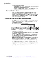
Page 10: ...ion IN THIS CHAPTER TQ10 Torque Drive Description Block Diagram TQ10SD Step Direction Drive Description Block Diagram C H A P T E R O N E Artisan Technology Group Quality Instrumentation Guaranteed 888 88 SOURCE www artisantg com ...

Page 11: ...que Servo Drive Motor Motor Currents Hall Motor Temp Signals Encoder Signals Analog Command Voltage High Level Commands Host Computer or Programmable Controller Block Diagram TQ10 Torque Drive The host computer or programmable controller may or may not be necessary depending upon the motion controller s capabilities The analog command voltage is a torque command that represents commanded current I...

Page 12: ...coming step pulses represent commanded position and go into one of the inputs of a summing node Incoming encoder counts represent actual position and go into the other input of the summing node During a typical move actual position will differ from com manded position by at least a few encoder counts Actual position is subtracted from commanded position at the summing node the result is position e...

Page 13: ...ink fan unit and the covers installed at the factory Part numbers for these drives are TQ10 EHS and TQ10SD EHS The suffix EHS is an acronym for Enclosure Heat Sink Compumotor SM and NeoMetric Series Brushless Servo Motors Compumotor manufactures SM and NeoMetric Series servo motors you can use these motors with the TQ10 Drive Each motor is equipped with Hall effect sensors an encoder and a thermos...

Page 14: ...tallation 5 2 Installation IN THIS CHAPTER Product Ship Kit List Installation Procedure Tuning C H A P T E R T W O Artisan Technology Group Quality Instrumentation Guaranteed 888 88 SOURCE www artisantg com ...

Page 15: ...33BD NTQN SM233BE NTQN NeoMetric Motor Information NeoMetric with NeoMetric with NeoMetric 500 Line Encoder 1000 Line Encoder Motor Cables N0701DD NTQN N0701DE NTQN 70TQ Cable 10 N0701FD NTQN N0701FE NTQN 1 set 10 cables N0702ED NTQN N0702EE NTQN 70TQ Cable 25 N0702FD NTQN N0702FE NTQN 1 set 25 cables N0703FD NTQN N0703FE NTQN 92MS Cable 10 N0703GD NTQN N0703GE NTQN 1 set 10 cables N0704FD NTQN N0...

Page 16: ...8 9 10 SHUTDOW N SHUTDOW N ENCODER GND ENCODER 5 ENCODER A ENCODER A ENCODER B ENCODER B RESERVED RESERVED 1 2 3 4 ENABLE IN ENABLE GND FAULT OUT FAULT OUT P I D 4 5 6 7 8 9 10 HALL GND HALL 5 V HALL 1 HALL 2 HALL 3 MOTOR TEMP MOTOR TEMP Com pum oto r Com pum oto r TQ10SD MOTOR FAULT DRIVE OVERTEMP GRN REGEN RED OVERVOLTAGE GRN PEAK CURRENT RED IN FOLDBACK GRN POWER ON RED NOT ENABLED 1 2 3 4 5 6 ...

Page 17: ...ication Two 6 position DIP switches Switch 1 SW1 and Switch 2 SW2 are located on top of the drive The table below summarizes their settings A 3 position DIP switch Switch 3 SW3 is located on the bottom of the drive See the section after this for instructions on setting SW3 Default Settings The factory default position is off for all switches You must set these switches appropri ately for your appl...

Page 18: ... 2 1 6 1 2 3 4 5 6 SW 1 1 6 TQ10 DIP SWITCH SETTINGS amps seconds setting number on on off off on on off on on on on off off off on off on off on off on 1 0 1 2 1 4 1 6 3 3 5 0 10 0 DIP Switch Settings for Compumotor SM and NeoMetric Motors with foldback enabled 0 1 5 3 0 4 4 6 0 7 4 8 9 10 0 off off off off off on on off off on off on off on off off on on on on off on on on 0 1 2 3 4 5 6 7 Foldba...

Page 19: ...sistance The suggested settings provide wide current loop bandwidth In some applications lower bandwidth may allow easier position loop tuning To reduce bandwidth set the loop gain DIP switch for lower gain by one or two settings Do not set loop gain higher than the suggested setting DIP Switch Settings for SM and NeoMetric Motors DIP switch settings for Compumotor SM and NeoMetric motors are show...

Page 20: ...ved N0703F N0703G N0704F N0704G N0921F N0921G N0922G TQ10 DIP SWITCH 3 If you use a non Compumotor motor see the Appendix at the end of this User Guide for information about setting DIP switches for your motor Offset Potentiometer Do Not Adjust Located next to DIP SW3 is a small potentiometer that controls the drive s offset It was adjusted at the factory and requires no further adjustment WARNING...

Page 21: ... 5 2 45 62 2 1 23 31 1 Unpainted for electrical grounding 2 x clearance for 10 M5 mounting screw 0 55 14 0 minimum clearance for connectors and wiring Dimensions TQ10 Torque and TQ10SD Step Direction Servo Drives 9 44 239 8 0 80 20 3 2 45 62 2 1 23 31 1 0 20 5 1 9 0 228 51 10 00 254 0 48 12 1 2 x clearance for 10 M5 mounting screw Fan and heatsink are standard with TQ10 EHS and TQ10SD EHS 1 5 38 1...

Page 22: ...tsink The mounting surface may be adequate as a heatsink provided it has sufficient mass and surface area The mounting plate at the rear of the drive is a heatplate it is a thermal pathway through which the drive can dissipate its excess heat Mount the drive to a suitable heat sinking surface A thermally conductive strip is provided with the drive When you mount the drive install the strip between...

Page 23: ...without heatsink fan units attached to the drive 8 50 215 9 Dimensions in inches millimeters Dimensions without Heatsink Fan Unit attached Dimensions with Heatsink Fan Unit attached 2 95 74 9 Min 2 95 74 9 Minimum 1 50 38 1 Minimum Clearance 0 50 12 7 Minimum Clearance 0 50 12 7 Minimum Clearance 2 00 50 8 Minimum Clearance 10 00 254 0 2 95 74 9 Minimum 0 70 17 8 Minimum Clearance 0 50 12 7 Minimu...

Page 24: ...f the drive are available from Compumotor part number TQ ENCL The drawing above shows how to attach these optional parts to your TQ10 Drive Because the covers will reduce convection available for cooling internal components drive temperature may increase You may need to reduce ambient temperature or provide forced air cooling to cool the drive You may also need to install an external regeneration ...

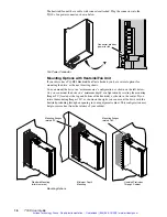
Page 25: ...by rotating the mounting flanges 90 located at the top and bottom of the heatsink as shown in the center If you rotate the mounting flanges 180 as shown on the right you can mount the drive with the heatsink protruding through an opening in your equipment cabinet This configuration may help to remove heat from the interior of your cabinet Mo tio n Co nt ro l Mo tio n Co nt ro l Mo tio n Co nt ro l...

Page 26: ...gineers 800 358 9070 about shaft modifications as a custom product Motor Heatsinking Performance of a servo motor is limited by the amount of current that can flow in the motor s coils without causing the motor to overheat Most of the heat in a brushless servo motor is dissipated in the stator the outer shell of the motor Performance specifications usually state the maximum allowable winding or ca...

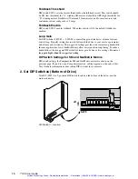
Page 27: ...ture Connections Front of Drive 14 AWG 2 5 mm2 is the maximum wire size that can fit in the connector Connect Motor Thermostat Wires Connect your motor s thermostat wires to MOTOR TEMP and MOTOR TEMP If your motor does not have a thermostat short MOTOR TEMP and MOTOR TEMP together by connecting an insulated jumper wire between them The drive will experience a motor fault if neither a thermostat no...

Page 28: ...otor damage A thermal switch may not protect the motor if the motor heats up too quickly Do not allow instability to persist longer than a few seconds After each incident of instability allow the motor to cool for several minutes Connect Motor Phase Wires Connect your motor s phase wires and ground wire to the removable 7 pin MOTOR connector located on the bottom of the drive The next drawing show...

Page 29: ...ctions for SM and NeoMetric Series Motors Inside the motor cable there are two sets of wires One contains Hall effect and motor thermostat wires the other contains motor phase wires Each set of wires has its own shield and shield drain wire As shown in the drawing you should connect both drain wires and the green yellow ground wire to the MOTOR GROUND connector Optional Connect an External Regener...

Page 30: ...olor LED labeled REGEN OVERVOLTAGE will be illuminated red This is a latched fault cycle power to resume operations with the TQ10 Torque Drive you can also toggle the reset input to resume operations If excessive regeneration causes overvoltage faults in your system you can install an external regeneration resistor Ensure that the external resistor is adequately mounted and cooled Excessive heatin...

Page 31: ...he power bus is shared This improves system efficiency by using energy that would otherwise be wasted Connecting Motors from Other Vendors Before connecting a motor from another vendor you must determine which motor phase wires correspond to Phase A Phase B and Phase C inputs on the TQ10 Similarly you must determine which Hall effect wires correspond to Hall 1 Hall 2 and Hall 3 Connect each wire t...

Page 32: ...l Code NEC and your local electrical code to ensure you use proper grounding methods Proper grounding can also reduce electrical noise GROUND THE MOTOR CASE The motor case must be grounded to reduce electrical noise An ungrounded motor can cause electrical noise problems throughout the system particularly in encoder wiring and circuitry This noise may cause the encoder to output erroneous informat...

Page 33: ... can connect the input to an external voltage as high as 24V You can also connect it to a dry contact closure to ground If you need to disable the drive in an emergency use the enable input Connect a manual disable switch to the enable input as the next drawing shows The switch is normally closed When it is opened the drive will be disabled The load can freewheel therefore you should use a brake t...

Page 34: ...hort Circuit latched Power Supply Fault latched Foldback foldback causes fault if DIP SW2 Position 1 is set to ON Latched means you must cycle power before the drive will operate again or with the TQ10 Torque Drive you can also use the reset input to reset the drive You can use the TQ10 s fault output as a signal to a controller or PLC that a fault has occurred The following drawing shows several ...

Page 35: ...n Connect your controller s command output signal to the TQ10 s command input terminals The following sections describe how to connect different types of controller outputs to the TQ10 s command input terminals Controller with Single ended Output If your controller uses a single ended output a single terminal that produces a voltage that ranges from 10VDC to 10VDC connect that output to COMMAND on...

Page 36: ...r with Isolated Output Some controllers have isolated command outputs and may require a voltage source to power their outputs The TQ10 has three pins available to power isolated outputs on a controller These pins provide 15VDC 15VDC and ground The next figure shows a typical controller with isolated differential outputs and illustrates how you can connect it to the TQ10 20KΩ 20KΩ 10KΩ 10KΩ 7 COMMA...

Page 37: ...while Direction is positive the drive will make the motor turn in the positive direction a distance of one positive encoder count For stability it is important that you connect your system so that a positive step command causes the encoder position to increment not decrement If the system is connected incorrectly each step pulse will cause the encoder to move in the wrong direction causing increas...

Page 38: ...onics 681Ω Internal Connections B B 26LS32 681Ω 681Ω Internal Connections for CHA and CHB are identical MOTOR Encoder 3 ENCODER GND 4 ENCODER 5 5 ENCODER A 6 ENCODER A 7 ENCODER B 8 ENCODER B Encoder Input Specifications Maximum low input 0 8V Minimum high input 2 0V Maximum input frequency 1 MHz A Leads B CW Rotation B Leads A CCW Rotation TQ10SD Motor 5V 200mA max at 5V available to power encode...

Page 39: ...nded position and reestablishes servo action While the TQ10SD is in shutdown it s small internal offset torque will be applied to the load This torque is usually too low to overcome friction and cause motion In some applications however the shaft may need to be held in the desired position during shutdown Note that shutdown in the TQ10SD functions differently than shutdown in a step motor drive Wh...

Page 40: ...d by shaft motion or the CPE limit is reached Reaching the limit causes a fault that disables the drive and illuminates the red LED labeled NOT ENABLED To clear the position error fault cycle power Velocity Monitor Output Optional The TQ10SD s velocity monitor output is a voltage signal proportional to encoder speed You can connect a voltmeter to this output to measure velocity or you can connect ...

Page 41: ...ic for the input is shown in the next drawing See Tuning at the end of this chapter for more information Internal Connections 5V 26LS32 10KΩ 10KΩ 5 D GAIN RED 6 I GAIN OFF 8 GND 26LS32 TQ10SD Derivative Gain Reduction Integral Gain Disable Inputs 7 Connect AC Power At this point in your installation procedure you should have mounted your drive and motor and connected motor cables and controller ca...

Page 42: ...counterclockwise direction Verify that the motor turns as commanded Test any of the optional inputs and outputs that you have connected You may need to tune your system before you can obtain motion from the motor We give tuning instructions later in this chapter Successful completion of this procedure will verify that your controller and motor are correctly connected to the TQ10 and that the drive...

Page 43: ... a double flex coupling in this situation it will allow too much freedom and the shaft will rotate eccentrically which will cause large vibrations and catastrophic failure Do not use a single flex coupling with a parallel misalignment this will bend the shafts causing excessive bearing loads and premature failure Double Flex Coupling Use a double flex coupling whenever two shafts are joined with p...

Page 44: ...SM or NeoMetric Series motor or other high performance servo motor be careful not to overheat the motor while tuning your system If you acciden tally choose tuning gains that cause motor oscillations or instability excess motor current can quickly overheat and damage the motor even before the thermostat can trigger the motor overtemperature circuit CAUTION For initial tuning with an SM or NeoMetri...

Page 45: ...sfy your motion requirements not every application requires maximum peak current Verify Thermal Stability Run your application for at least four thermal time constants to ensure that the motor stabilizes at an acceptable temperature Example An SM232A motor s current ratings are 2 1A continuous 6 3A peak its thermal time constant is 35 minutes The motor is to be used in an application that requires...

Page 46: ...ected by changes in the propor tional gain tuning potentiometer This arrangement simplifies tuning once you set the integral and derivative gains in the correct ratio to proportional gain you only need to adjust proportional gain integral and derivative gain will follow Derivative Gain Derivative gain provides a torque that is directly proportional to the rate of change of the error signal When th...

Page 47: ...s of the move which should decrease overshoot and settling time When the system reaches constant velocity or comes to rest use your control signal to break the ground connection which will re enable integral gain Tuning Procedure In the procedure given below you will systematically vary the tuning potentiometers until you achieve a move that meets your requirements for accuracy and response time Y...

Page 48: ...ed if you disable it now and re enable it in Step 6 of the tuning procedure Set up the Velocity Monitor optional Connect an oscilloscope to the velocity monitor output as described earlier in the Inputs and Outputs section Its use is optional however because the velocity monitor clearly shows your system s response when you adjust the potentiometers we recommend using it Set Potentiometers to thei...

Page 49: ...ur actual move If the move is successful and your motion requirements are satisfied you do not need to increase peak current any higher you may proceed to Step 6 If the move is not successful proceed to Step 4 in which you will increase peak current Increase peak current Using the DIP switches increase peak current to 6 0 amps for SM motors with A windings 10 0 amps for all other motors Do not exc...

Page 50: ...or Specifications SM and NeoMetric Motor Speed Torque Curves SM and NeoMetric Motor Dimensions SM and NeoMetric Encoder Specifications SM and NeoMetric Motor Part Numbering System C H A P T E R T H R E E Artisan Technology Group Quality Instrumentation Guaranteed 888 88 SOURCE www artisantg com ...

Page 51: ...hort Circuit Phase to phase phase to earth Brownout Below 80VAC Over temperature Motor 90 C 194 F Drive 65 C 150 F Outputs TQ10 TQ10SD Reference 15V 10 mA available Encoder Power 5VDC 200mA max Fault 5 24VDC 20mA max current 5 24VDC 20mA max current Fault Pull up resistor needed No fault Pull up resistor needed No fault transistor on current flows transistor on current flows Output turns off under...

Page 52: ...9 0 78 4 08 1 06 Thermal Resistance1 Rth C watt 2 75 2 00 2 23 1 58 1 50 1 25 1 26 Thermal Time Constant Tth minutes 30 30 30 35 35 40 40 Electrical Time Constant Tte milliseconds 0 178 0 21 0 31 0 39 0 39 0 42 0 41 Mechanical Time Constant Tm milliseconds 9 2 5 0 13 7 8 6 8 8 5 4 7 0 Rotor Inertia J lb in sec2 0 000094 0 00016 0 00046 0 00082 0 00082 0 00117 0 00117 oz in2 mass 0 58 0 99 2 84 5 0...

Page 53: ...95 1 24 3 12 2 24 3 46 2 50 4 14 2 99 Resistance3 R ohms 5 52 2 27 5 22 2 7 3 36 1 74 3 47 1 80 Inductance5 L millihenries 12 98 5 23 15 86 8 16 12 13 6 30 14 50 7 55 Thermal Resistance1 Rth C watt 1 44 1 44 1 15 1 15 0 96 0 96 0 87 0 87 Motor Constant Km lb in watt 0 83 0 83 1 37 1 36 1 89 1 89 2 23 2 23 Viscous Damping B lb in Krpm 0 044 0 044 0 05 0 05 0 0563 0 0563 0 0625 0 0625 Torque Static ...

Page 54: ... Inductance5 L millihenries 17 11 8 99 14 72 Thermal Resistance1 Rth C watt 1 06 1 06 0 77 Motor Constant Km lb in watt 1 96 2 00 3 29 Viscous Damping B lb in Krpm 0 075 0 075 0 0875 Torque Static Friction Tf oz in 4 4 6 Thermal Time Constant τth minutes 60 60 60 Electrical Time Constant τe milliseconds 4 6 4 6 6 4 Mechanical Time Constant τm milliseconds 1 13 1 13 0 64 Rotor Inertia J lb in sec2 ...

Page 55: ...m 0 2000 33 4000 67 6000 100 8000 133 1000 17 3000 50 5000 83 7000 117 RPM rps 0 Torque Speed TQ10 with SM233A 100 0 71 200 1 41 300 2 12 400 2 82 500 3 54 600 4 24 700 4 94 oz in N m 0 1000 17 2000 33 3000 50 4000 67 500 8 5 1500 25 2500 41 3500 58 RPM rps 0 Torque Speed 100 0 71 300 2 12 400 2 82 200 1 41 TQ10 with SM232A oz in N m 0 2000 33 4000 67 6000 100 8000 133 1000 17 3000 50 5000 83 7000...

Page 56: ...0 1000 2000 3000 4000 5000 0 5 10 15 20 25 30 0 1000 2000 3000 4000 5000 6000 7000 8000 0 5 10 15 20 0 1000 2000 3000 4000 5000 6000 7000 8000 0 5 10 15 20 25 560 1 68 2 24 1 12 3 36 560 1 68 2 24 1 12 2 80 560 1 68 2 24 1 12 2 80 Torque Speed TQ10 with N0702F N0342F Torque Speed TQ10 with N0702E N0342E Torque Speed TQ10 with N0701D N0341D lb in N m lb in N m lb in N m Artisan Technology Group Qua...

Page 57: ...r Dimensions Compumotor SM Series Size 23 Cable Option Flying Leads Cable Options Motor Sizes Part FL 10 Description 18 Flying Leads 10 ft Cable 233 Motor 5 98 151 89 232 Motor 4 98 126 49 231 Motor 3 98 101 09 Model Motor Length Longer lengths available Consult Compumotor for information Motor Length 0 75 19 05 0 81 20 57 Ø0 3750 0 0000 0 0005 9 525 0 0000 0 0127 Ø1 500 38 1 0 001 0 025 F Flat Sh...

Page 58: ...ru Holes Eq Spaced on a Ø 2 953 75 00 Bolt Circle for 5mm or 10 Bolt Motor Dimensions Compumotor NeoMetric Series Size 34 Shaft Options 0 473 12 01 Ø0 500 12 7 N None F Flat K Sq Key 0 56 14 22 0 228 5 8 0 500 12 7 0 125 3 175 Ø0 5000 0 0000 0 0005 12 7 0 000 0 012 0 250 6 35 Motor Length 3 26 82 8 Motor Sizes 34 4 Brake 10 00 254 00 34 3 Brake 9 00 228 60 Model Motor Length 34 2 Brake 8 00 203 20...

Page 59: ... 3 62 91 95 Sq 4 x Ø0 281 7 14 Thru Holes Eq Spaced on a Ø 3 937 100 Bolt Circle for 6mm or 1 4 Bolt Feedback Conn MS 14 18 4 1 104 9 0 530 13 46 Motor Length 1 180 29 97 0 093 2 36 Ø0 5512 0 0003 0 0001 14 0 007 0 002 Ø3 1496 0 0005 0 0003 80 0 012 0 007 Encoder Specifications Compumotor SM NeoMetric Series Motors Parameter Value Performance Accuracy 2 min of arc Electrical Input Power 5VDC 5 135...

Page 60: ...xample SM 231AE NTQN 23 Frame 1 magnet A winding 1 000 line Encoder Normal Shaft TQ10 compatible No options Motor Part Numbering System Compumotor NeoMetric Series Servo Motor The diagram below illustrates the part numbering system for Compumotor NeoMetric Series servo motors N Series Winding Identifying character D E F etc Feedback D 500 ppr encoder2 E 1 000 ppr encoder H Hall effect only R Resol...

Page 61: ...52 TQ10 User Guide Artisan Technology Group Quality Instrumentation Guaranteed 888 88 SOURCE www artisantg com ...

Page 62: ...IN THIS CHAPTER Troubleshooting Basics Diagnostic LEDs Non Drive Related Problems Protective Circuits Product Return Procedure C H A P T E R F O U R Artisan Technology Group Quality Instrumentation Guaranteed 888 88 SOURCE www artisantg com ...

Page 63: ...rocedures You may need to review and consult these notes later This will also prevent you from duplicating your testing efforts Once you have isolated a problem take the necessary steps to resolve it Refer to the problem solutions contained in this chapter If the problem persists contact your local technical support resource Diagnostic LEDs The TQ10 Drive has five LEDs on its front panel The follo...

Page 64: ...th gravity transient undervoltage etc Check for problems caused by electrical noise Consult the heatsink Check mounting screws Provide sufficient ventilation Compumotor sales guide for possible solutions Check grounds Possible Source of Problem Problems During Move Some problems occur transiently during a move or do not affect the LEDs Others may be due to wiring mistakes or failure of other compo...

Page 65: ...e and the drive will shut down This is a latched fault To restart the drive first allow it to cool then cycle power or with the TQ10 Torque drive you can use the reset input You can prevent overtemperature faults by heatsinking the drive properly or adding the HS3 Heatsink Fan Unit option and maintaining ambient temperature at or below 50 C 122 F Short Circuit Protection The TQ10 Drive has short c...

Page 66: ...dback circuitry to help protect the motor Six of the DIP switches configure the foldback circuitry Three of them set the time that high current will be permitted before the foldback circuitry takes action Settings range from 1 to 10 seconds One switch defines what constitutes high current This is set according to Ics One switch will cause a latched fault to be generated when the selected time at h...

Page 67: ...ad to unaccept able consequences and continued motion even at a reduced rate is preferable An example of this would be a conveyor drive running product through an oven which is hot enough to melt the product eventually The default settings cause the timer to start when the current is approximately twice the motor s continuous rating 2 times Ics The thermal switches in Parker servo motors will prot...

Page 68: ...Through its MOTOR TEMP and MOTOR TEMP terminals the drive checks for electrical continuity provided by a normally closed thermostat mounted on the motor If the motor overheats and the thermostat opens the loss of continuity activates protection circuitry in the TQ10 it turns off power output to the motor and illuminates the MOTOR FAULT LED This is a latched fault To resume operations let the motor...

Page 69: ... unit configured in detail What if any cables were modified and how With what equipment is the unit interfaced What was the application What was the system environment temperature enclosure spacing unit orientation contaminants etc What upgrades if any are required hardware cables user guide In the USA call your Automation Technology Center ATC for a Return Material Authoriza tion RMA number Retur...

Page 70: ...on Compumotor Motors IN THIS APPENDIX Configuring DIP Switches Connecting Motor Phase Wires and Hall Effect Wires A P P E N D I X A Artisan Technology Group Quality Instrumentation Guaranteed 888 88 SOURCE www artisantg com ...

Page 71: ...ff off 1 2 3 4 5 6 SW 2 1 6 1 2 3 4 5 6 SW 1 1 6 TQ10 DIP SWITCH SETTINGS amps seconds setting number on on off off on on off on on on on off off off on off on off on off on off 1 0 1 2 1 4 1 6 3 3 5 0 10 0 0 1 5 3 0 4 4 6 0 7 4 8 9 10 0 off off off off off on on off off on off on off on off off on on on on off on on on 0 1 2 3 4 5 6 7 Foldback Disabled Foldback Enabled High Threshold Low Threshol...

Page 72: ...six possible phase wiring combinations only one will work properly Three will not work at all The other two deserve particular attention if the motor is wired in one of these two configurations the motor will turn but its performance will be severely impaired How can you tell if your motor is wired improperly If it is in one of the two poor performance configurations its torque will be much lower ...

Page 73: ...that make the motor turn and use the proper one If your motor turns in the opposite direction than you want you can reverse it using one of several methods Reverse the appropriate encoder connections Exchange two Hall input wires then follow steps 2 through 5 above Artisan Technology Group Quality Instrumentation Guaranteed 888 88 SOURCE www artisantg com ...

Page 74: ...Appendix B 65 BLVD Installation Instructions A P P E N D I X B IN THIS APPENDIX LVD Installation Instructions Artisan Technology Group Quality Instrumentation Guaranteed 888 88 SOURCE www artisantg com ...

Page 75: ...mer should be insulated to 2300V rms Do not interrupt the protective earth conductor between the source mains and the isolation transformer s secondary The core of the isolation transformer and the drive s protective conductor terminal must both be connected to the main s protective earth conductor CAUTION Do not use an autotransformer Line Fuses Line fuses need to be added to protect the transfor...

Page 76: ...greater than 0 1 ohm Use thicker gauge wire if the resistance is too high Mechanical Installing in an Enclosure TQ10 Drives must be installed within an enclosure The enclosure s interior must not be accessible to the machine operator The enclosure should be opened only by skilled or trained service personnel Servicing the TQ10 Drive Changing Firmware Only skilled or trained personnel should change...

Page 77: ...ings The following symbols may appear in this User Guide and may be affixed to the products discussed in this user guide Symbol Description Earth Terminal Protective Conductor Terminal Frame or ChassisTerminal Equipotentiality Caution Risk of Electric Shock Caution Refer to Accompanying Text Hot Surface Artisan Technology Group Quality Instrumentation Guaranteed 888 88 SOURCE www artisantg com ...

Page 78: ... Compumotor Application Support 60 A AC Power Input 32 Accessories 6 Actual Position 3 36 Ambient Temperature 13 Application Support 60 B Brushed Servo Motors operating connecting 22 Covers 15 CPE1 and CPE2 30 31 Current Foldback 57 Current Foldback Ratio 10 D Derivative Gain 37 Derivative Gain Reduction 32 37 Description TQ10 TQ10SD 2 Diagnostic LEDs 54 Differential Inputs 28 Differential Output ...

Page 79: ...on Error 3 30 36 Position Error Inputs 30 Potentiometer Locations 38 Power Bus 22 Power Input 32 Power Ratings 33 Product Description TQ10 TQ10SD 2 Product Return Procedure 60 Proportional Gain 37 Q Quick Test 8 R Regeneration 56 Regeneration Resistor 20 Reset Input 28 Resistor Regeneration 20 Resonance Issues 35 Return Procedure 60 RMA 60 Rotation Direction Definition 26 S Scaling 26 Shaft Rotati...

Page 80: ...r Temp Motor Temp SM Motor Cable 1 2 TQ10 Status LEDs see page 54 MOTOR FAULT DRIVE OVERTEMP REGEN OVERVOLTAGE PEAK CURRENT IN FOLDBACK POWER ON NOT ENABLED Red indicates short circuit in motor cabling or indicates motor overtemperature Red indicates drive has exceeded temperature limit Illuminates green during regen event illumates red if regen causes overvoltage Illluminates green during peak cu...

Page 81: ...quipment Have surplus equipment taking up shelf space We ll give it a new home Learn more Visit us at artisantg com for more info on price quotes drivers technical specifications manuals and documentation Artisan Scientific Corporation dba Artisan Technology Group is not an affiliate representative or authorized distributor for any manufacturer listed herein We re here to make your life easier How...

Reviews: