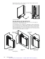
➁
Installation
7
Installation Overview
The order of topics in the installation procedure is:
•
Quick Test
•
Connecting a Controller
•
DIP Switch Configuration
•
Connecting AC Power
•
Drive Mounting & Heatsinking
•
Testing the System Installation
•
Motor Mounting
•
Connecting the Motor to the Load
•
Connecting the Motor to the Drive
•
Tuning
Installation Procedure
Topics in this chapter are arranged to lead you through the installation process in a step-by-
step manner. Complete each step before proceeding to the next.
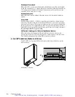
The next drawing shows locations and names of the various connectors, switches, and
components that you will encounter during the installation procedure.
\
DIP Switches
TQ10 Torque Servo Drive
TQ10SD Step & Direction Servo Drive
Motor Connector
DIP
Switches
AC Power Connector
Status LEDs
Inputs &
Outputs
Tuning Pots
(TQ10SD)
Hall &
Motor Temp
Signals
Heatsink
TQ10SD
TQ10SD
M
OT
OR
F
AU
LT
DR
IV
E O
VE
RT
EM
P
GR
N R
EG
EN
RE
D O
VE
RV
OL
TA
GE
GR
N P
EA
K C
UR
RE
NT
RE
D IN
F
OL
DB
AC
K
GR
N P
OW
ER
O
N
RE
D N
OT
E
NA
BL
ED
=
=
=
=
=
=
1
2
3
4
5
6
7
8
9
10
VE
L M
ON
IT
OR
CP
E2
ST
EP
+
DIR
EC
TIO
N +
D-G
AIN
R
ED
I-G
AIN
O
FF
CP
E 1
GN
D
ST
EP
-
DIR
EC
TI
ON
-
1
2
3
4
5
6
7
8
9
10
SH
UT
DO
W
N
+
SH
UT
DO
W
N -
EN
CO
DE
R G
ND
EN
CO
DE
R +
5
EN
CO
DE
R A
+
EN
CO
DE
R A
-
EN
CO
DE
R B
+
EN
CO
DE
R B
-
RE
SE
RV
ED
RE
SE
RV
ED
1
2
3
4
EN
AB
LE
IN
EN
AB
LE
G
ND
FA
UL
T O
UT
+
FA
UL
T O
UT
-
P
I
D
4
5
6
7
8
9
10
HA
LL
G
ND
HA
LL
+
5V
HA
LL
1
HA
LL
2
HA
LL
3
M
OT
OR
T
EM
P +
M
OT
OR
T
EM
P -
Compumotor
Compumotor
TQ10SD
MOTOR FAULT
DRIVE OVERTEMP
GRN REGEN
RED OVERVOLTAGE
GRN PEAK CURRENT
RED IN FOLDBACK
GRN POWER ON
RED NOT ENABLED
=
=
=
=
=
=
1
2
3
4
5
6
7
8
9
10
VEL MONITOR
CPE2
STEP +
DIR
D-GAIN RED
I-GAIN OFF
CPE 1
GND
STEP -
DIRECTION -
1
2
3
4
5
6
7
8
9
10
SH
SHUTDOWN -
ENCODER GND
E5
ENCODER A +
ENCODER A -
ENCODER B +
ENCODER B -
RESERVED
RESERVED
1
2
3
4
5
6
ENABLE IN
ENABLE GND
FAULT OUT +
FAULT OUT -
RESET IN
RESET GND
P
I
D
4
5
6
7
8
9
10
HALL GND
HALL +5V
HALL 1
HALL 2
HALL 3
MOTOR TEMP +
MOTOR TEMP -
Automation
Automation
Automation
Automation
TQ10
MOTOR FAULT
DRIVE OVERTEMP
GRN REGEN
RED OVERVOLTAGE
GRN PEAK CURRENT
RED IN FOLDBACK
GRN POWER ON
RED NOT ENABLED
=
=
=
=
=
=
1
2
3
4
5
6
7
8
9
10
ENABLE IN
ENABLE GND
FAULT OUT +
FAULT OUT -
RESET IN
RESET GND
C
COMMAND -
COMMAND SHLD
GND
1
2
3
4
5
6
7
8
9
10
GND
+ 15V
- 15V
HALL GND
HALL +5V
HALL 1
HALL 2
HALL 3
MOTOR TEMP +
MOTOR TEMP -
Compumotor
Compumotor
Compumotor
Compumotor
TQ10 & TQ10SD – Component Locations
Artisan Technology Group - Quality Instrumentation ... Guaranteed | (888) 88-SOURCE | www.artisantg.com

