➁
Installation
25
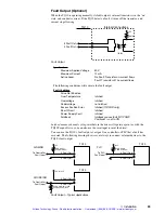
Fault Output (Optional)
When the TQ10 is operating normally, its fault output’s internal transistor is in the “on”
state, and conducts current. If the TQ10 detects a fault, it turns off the transistor, and
current stops flowing.
Internal Connections
4 Fault Out–
3 Fault Out+
TQ10
+5V
ILD223
681
Ω
Fault Output
Specifications
Maximum Applied Voltage
50 V
Maximum Current
10 mA
Active Level
No Fault: Transistor
on, current flows
Fault: Transistor
off, no current flows
The following conditions will activate the fault output.
Fault Condition
Drive Not Enabled
Over Temperature
latched
Overvoltage
latched
Undervoltage
not latched
Excess Position Error
latched (TQ10SD only)
Short Circuit
latched
Power Supply Fault
latched
Foldback
foldback causes fault if DIP SW2,
Position#1 is set to ON
Latched
means you must cycle power before the drive will operate again (or, with the
TQ10 Torque Drive, you can also use the reset input to reset the drive).
You can use the TQ10’s fault output as a signal to a controller or PLC that a fault has
occurred. The following drawing shows several ways to connect external devices to the
TQ10’s fault output.
4 Fault Out–
3 Fault Out+
To Controller
Fault Input
TQ10
SINKING
+5V
1K
Ω
typical
500
Ω
minimum
2.5K
Ω
minimum at 24V
500
Ω
minimum at 5V
4 Fault Out–
3 Fault Out+
To PLC
Fault Input
TQ10
PLC
+24V
10K
Ω
typical
2.5K
Ω
minimum
4 Fault Out–
3 Fault Out+
To Controller
Fault Input
TQ10
SOURCING
+5V to +24V
Fault Output – Typical Applications.
Artisan Technology Group - Quality Instrumentation ... Guaranteed | (888) 88-SOURCE | www.artisantg.com


