Table of Contents
3
Specifications Table................................... 4
1.1.
Fax Function .............................................4
1.2.
Printer Function ......................................12
1.3.
External View..........................................13
1.4.
Control Panel ..........................................15
Disassembly Instructions ......................... 16
2.1.
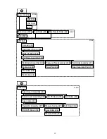
General Disassembly Flowchart .............16
2.2.
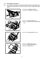
Disassembly Instructions ........................18
2.3.
Screw Identification Template.................39
Check Points............................................ 41
3.1.
Required Tools .......................................41
3.2.
Periodic Check Points.............................41
3.3.
Periodic Maintenance Check List ...........42
3.4.
Updating the Firmware ...........................43
3.5.
Glossary of Electrical Abbreviations .......44
3.6.
SC PC Board ..........................................47
3.7.
Power Supply Unit ..................................58
3.8.
PNL PC Board ........................................59
3.9.
SNSE PC Board .....................................62
3.10. ILS PC Board..........................................63
3.11. SNST PC Board......................................64
3.12. ACI PC Board .........................................65
3.13. SRU PC Board (Optional).......................66
Troubleshooting ....................................... 67
4.1.
Initial Troubleshooting Flowchart ............67
4.2.
Improper LCD Display ............................68
4.3.
Information Codes (INFO. CODES)........69
4.4.
Printed Copy Quality Problems...............81
4.5.
Document Feeder (ADF) ........................97
4.6.
Communications ...................................100
4.7.
Information Codes Table
(For Facsimile)......................................106
4.8.
Diagnostic Codes (For Facsimile).........111
Service Modes ....................................... 118
5.1.
Service Modes (For Facsimile) .............118
System Description................................ 163
6.1.
Mechanical Operation ..........................163
6.2.
Electrical Circuit Explanation ................173
Exploded View & Parts List.................... 199
7.1.
Country Codes......................................199
7.2.
Control Panel Unit.................................200
7.3.
ADF Unit............................................... 203
7.4.
Fuser Unit............................................. 205
7.5.
ASF Unit ............................................... 207
7.6.
Drive Unit ............................................. 210
7.7.
Base Unit.............................................. 212
7.8.
PC Board / Harness ............................. 214
7.9.
Cartridge Unit ....................................... 216
7.10. Packing and Accessories ..................... 218
Installation ............................................. 221
8.1.
Function Key ........................................ 221
8.2.
Main Unit and Accessories................... 222
8.3.
Installing the Accessories..................... 223
8.4.
Installing the Toner Cartridge ............... 224
8.5.
Loading the Recording Paper .............. 227
8.6.
Connecting the Telephone Line Cable
and Power Cord ................................... 228
8.7.
Customizing Your Machine .................. 229
Schematic Diagram ............................... 234
9.1.
General Circuit Diagram....................... 234
9.2.
SC PC Board........................................ 235
9.3.
PNL PC Board...................................... 245
9.4.
ILS PC Board ....................................... 248
9.5.
SNST PC Board ................................... 249
9.6.
SNSE PC Board ................................... 250
9.7.
ACI PC Board....................................... 251
9.8.
Power Supply Unit
(For USA / Canada) ............................. 252
9.9.
Power Supply Unit
(For Other Countries) ........................... 254
Summary of Contents for Panafax UF-490
Page 2: ...2 ...
Page 15: ...15 1 4 Control Panel For USA and Canada For Other Countries ...
Page 37: ...37 24 Remove the Pressure Roller 322 25 Remove the Exit Roller 304 24 25 ...
Page 63: ...63 3 10 ILS PC Board CN73 Refer to SC PC Board CN11 ...
Page 65: ...65 3 12 ACI PC Board Refer to Power Supply Unit CN101 ...


