145
5.1.4.3.
DTMF Signal
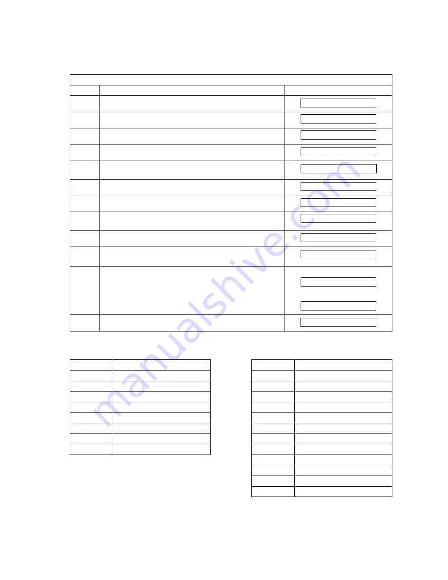
This Service Mode is used to check the DTMF (Dual Tone Multi Frequency) signal output.
The DTMF signal can be generated using the following procedure.
Service Mode 4 - DTMF Signal
Step
Operation or Unit Condition
LCD Display
1
Standby
2
Press “FUNCTION” and then “7”.
3
Press “MONITOR” four times, then press “*”.
4
Press “4”.
5
Press “3” or
use “V” or “/\ “ to scroll to the desired Modem Test.
6
Press “SET”.
7a
Press "START" for DTMF Single Tone Generation.
8a
Enter the signal number (1-8) to select the DTMF
signal.
7b
Press "2" and "START" for Dual Tone Generation.
8b
Enter the signal number (0-#) to select the DTMF Dual
tone.
9
Press "CLEAR" to end the signal generation. To select
another signal, repeat step 7a or 7b.
7a
7b
10
Press "STOP" twice to return to standby.
DTMF Single Tone Table
DTMF Dual Tone Table
Number
DTMF Signal Tones
Number
DTMF Dual Tones
1
697 Hz
0
941 Hz + 1336 Hz
2
770 Hz
1
697 Hz + 1209 Hz
3
852 Hz
2
697 Hz + 1336 Hz
4
941 Hz
3
697 Hz + 1477 Hz
5
1209 Hz
4
770 Hz + 1209 Hz
6
1336 Hz
5
770 Hz + 1336 Hz
7
1477 Hz
6
770 Hz + 1477 Hz
8
1633 Hz
7
852 Hz + 1209 Hz
8
852 Hz + 1336 Hz
9
852 Hz + 1477 Hz
*
941 Hz + 1209 Hz
#
941 Hz + 1477 Hz
OCT-12 10:58 00%
SET MODE (1-8)
SERVICE MODE
SIGNAL TEST
DTMF TEST
SINGLE
ENTER (1-8)
697 Hz
ENTER (0-#)
(0)
SINGLE
DUAL
OCT-12 10:58 00%
Summary of Contents for Panafax UF-490
Page 2: ...2 ...
Page 15: ...15 1 4 Control Panel For USA and Canada For Other Countries ...
Page 37: ...37 24 Remove the Pressure Roller 322 25 Remove the Exit Roller 304 24 25 ...
Page 63: ...63 3 10 ILS PC Board CN73 Refer to SC PC Board CN11 ...
Page 65: ...65 3 12 ACI PC Board Refer to Power Supply Unit CN101 ...


