No. SX-DSV02310 - 27 -
R2.0 Motor
Business
Division,
Appliances Company, Panasonic Corporation
4-2-2 Command header (command byte 0)
Byte
bit 7
bit 6
bit 5
bit 4
bit 3
bit 2
bit 1
bit 0
0
C/R(0)
Update_Counter
MAC-ID (0–31)
Title
Description
C/R
• C/R bit distinguish command and response.
• Set this bit to 0 in command.
• If this bit is set to level other than 0, Err. 86.0 RTEX cyclic data error protection 1 alarm will be
generated.
Update_Counter
• Set the count up value at the command updating cycle.
• The purpose is to detect the command updating timing at servo driver.
• The servo driver echoes back this data in the response; the counter can also be used as the watchdog
timer.
MAC-ID
• Set up the node address of the servo driver.
• If a node address different from actual setting value is used, Err. 86.0 RTEX cyclic data error protection
1 alarm will be generated.
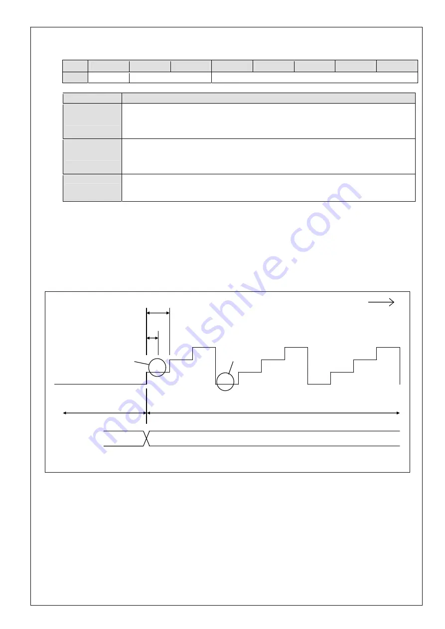
4-2-2-1 Update_Counter setup
Be sure to count up Update_Counter every command updating cycle at the data updating timing of the host controller.
Otherwise, operation command is not correctly received.
Because the counter used here is for the purpose of transferring the command updating timing to the servo driver,
regardless of actual updating process, count up operation must be done even if the content of the command data block
is unchanged.
*1) Set 1 to update counter at transmission of 1st valid data.
*2) When the counter overflowed, repeat from 0.
1
0
Command update cycle of host controller
(1 ms)
Communication
period
(500
s)
Transmission of invalid data
after canceling the reset
Transmission of valid data
0
2
3
Command
code
00h (NOP)
20h (Cyclic Position Command)
*2)
*1)
1
2
3
0
1
2
3
Time
<Example for setting of update counter (when command update cycle is 1 ms)>


