


318
Tr
oubleshootin
g
Cha
p
ter 1
5
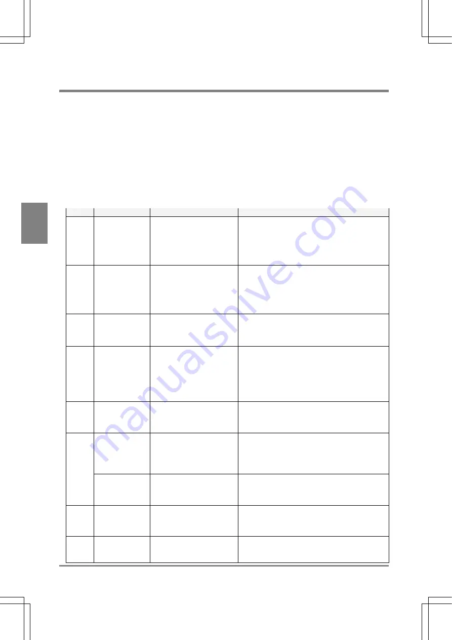
15.2 Error Code Number Is Displayed in SETUP Mode
If the values to be detected are incorrect but error signal is not output when performing inspection (for example, 0 is
output as detection data ), inspection may not performed properly with each checker. Check the settings of
checkers first, make sure for correct settings by following the procedure below.
Setting procedure:
1. Switch to SETUP mode.
2. Select
“CHECKER”.
3. Point the cursor to the checker of incorrect inspection result and the checker for position and
rotation adjustment.
4. Check whether or not the following codes are displayed in the status display area.
Code
Relative checker
Problem
Solution
E0044 Position
adjustment
/Rotation
adjustment
• Gray
edge
• Binary
edge
Cannot detect an edge that
fulfils the specified limits.
Change each setting value for the checkers or adjust
image brightness by adjusting the size of the aperture
of a lens and slice level so that edge can be detected.
E0045 Position
adjustment
/Rotation
adjustment
• Feature
extraction
Area (a group of pixels) that
fulfills the specified limits
cannot be detected.
Make sure the areas you want to detect fulfill the
specified conditions.
• Properly adjust max. or min. area limit for the
areas you want to detect.
• If the areas to be detected may position on the
area frame, activate “Boundary Process“.
E0046 Rotation
Adjustment
• Feature
Extraction
The theta of detected area (a
group of pixels) cannot be
detected.
For the figure of which principal axis angle such as
square, perfect circle, equilateral triangle, cross joint
cannot be detected. In this case, set “Theta” to “No”.
E0047 Position
adjustment
/Rotation
adjustment
• Matching
• Contour
matching
Image that fulfills the specified
limits cannot be detected.
Check the set conditions
• Are you taking the same object as the object that
has been registered as a template?
• Is “Coor.” Set to an appropriate value? The higher
“Coor.” Value the more tough inspection is. The
initial value is “0.60”. Change the value as
necessary.
E0049 Position
adjustment
/Rotation
adjustment
No base position is registered. Register a base position.
Feature extraction The pixel area fulfilling the
specified conditions (more
than 2001 pixel groups) were
detected
To avoid detecting unnecessary areas, refer to the
followings:
• Adjust max. or min. area limit.
• Adjust aperture on the lens and slice level to
detect only the areas that should be captured.
E0073
Smart matching
The number of pixel clusters
having the difference in the
grayscale exceeds 128.
Adjust the setting values of Subtraction Threshold,
Filter and Subtraction Area Min. so that the number of
pixel clusters having the difference in grayscale does
not exceed 128.
E0074
All
Frame of inspection area is
set out of the screen display
after position adjustment and
rotation adjustment.
Set the inspection frame within the display area by
minimizing the frame of inspection area in size or
extending the view range.
E0076
All
The Position Adjustment or
Rotation Adjustment checker
cannot detect the object.
Adjust a parameter of the checker for position
adjustment or rotation adjustment so that the object
can be detected.
Summary of Contents for Micro-Imagechecker PV310
Page 1: ......
Page 9: ...1 Names and Functions of Parts Chapter 1 Chapter 1 Names and Functions of Parts ...
Page 22: ......
Page 23: ...15 Installation and Wiring Chapter 2 Chapter 2 Installation and Wiring ...
Page 35: ...27 Input and Output Interface Ports Chapter 3 Chapter 3 Input and Output Interface Ports ...
Page 76: ......
Page 107: ...99 Setting Checkers Chapter 6 6 7 Gray Edge 6 7 1 Menu Options ...
Page 114: ...106 Setting Checkers Chapter 6 6 8 Feature Extraction 6 8 1 Menu Options ...
Page 121: ...113 Setting Checkers Chapter 6 6 9 Smart Matching 6 9 1 Menu Options ...
Page 137: ...129 Setting Checkers Chapter 6 6 11 Flaw Detection 6 11 1 Menu Options ...
Page 207: ...199 TOOL Chapter 8 Chapter 8 TOOL ...
Page 224: ......
Page 225: ...217 Environment Settings Chapter 9 Chapter 9 Environment Settings ...
Page 249: ...241 Chapter 10 Parallel Communication Chapter 10 Parallel Communication ...
Page 265: ...257 Chapter 11 RS 232C Communication Chapter 11 RS 232C Communication ...
Page 298: ......
Page 299: ...291 Chapter 12 Ethernet Communication Chapter 12 Ethernet Communication ...
Page 303: ...295 Chapter 13 Using a Compact Flash Memory Card Chapter 13 Using a Compact Flash Memory Card ...
Page 323: ...315 Chapter 15 Troubleshooting Chapter 15 Troubleshooting ...
Page 328: ......
Page 329: ...321 Chapter 16 Camera Switching Unit Chapter 16 Camera Switching Unit ...
Page 333: ...325 Chapter 17 General Specifications Chapter 17 General Specifications ...
Page 340: ......
Page 341: ...333 Chapter 18 Product Numbers Chapter 18 Product Numbers ...
Page 347: ...339 Chapter 19 Dimensions Chapter 19 Dimensions ...
Page 349: ...341 Chapter 19 Dimensions Double Speed Random Camera C Mount ANM831 Unit mm ...
Page 352: ...344 Dimensions Chapter 19 ANM88281 ANM88081 ANM8804 ANM88161 ANM88251 Unit mm ...
Page 356: ......
Page 357: ...349 Chapter 20 Appendix Chapter 20 Appendix ...
Page 358: ...350 Appendix Chapter 20 20 1 Pin Assignment of Camera Double Speed Random Camera ANM831 ...
Page 359: ...351 Chapter 20 Appendix Standard Camera ANM832 ANM83203 ...
Page 363: ...355 Record of Changes Manual No Date Revision detail ARCT1F456E March 2009 First Edition ...


