background image


194 

Cha

p

ter 7 

Calculation

, Anal

ysis
, a

nd Out

p

ut o

f Ins
p

ection Result

7.5.2  Data Can Be Displayed in the Data Monitor Table 

The data listed below can be referred to the Data Monitor. 
 

Reference Data 

No. 

Content 

Title - 

Titles 

containing 

numbers, alphabets and symbols 

Result of Numeric 
Calculation 

01 to 96 

Calculation result of a Numeric Calculation formula 

Judgment of Numeric 
Calculation 

01 to 96 

Judgment result of a Numeric Calculation formula 

Judgment of Judgment 
Calculation 

01 to 96 

Judgment result 

00 Scan 

Number 

OK Count 
NG Count 
OK Average 
OK Disperse 
Max. 
Min. 

Calculation 
Result 

Statistics 

01 to 96 

Range 

Product Type 

The number of current product type 

7.5.3 Data 

Displaying 

Result of Numeric Calculation and Judgment of Numeric/Judgment Calculation 

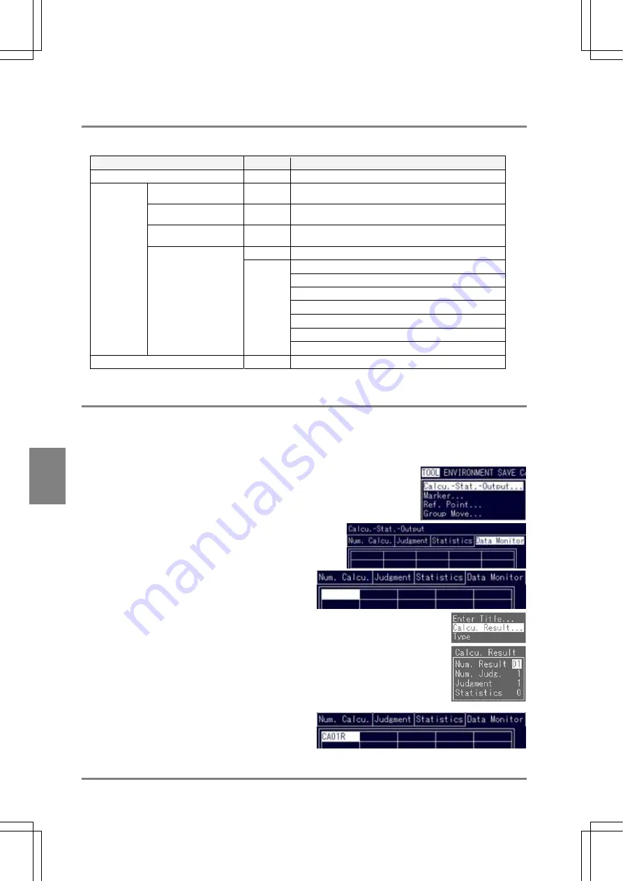
To refer the result and judgment of numeric calculation and judgment of judgment calculation, follow the steps 
below. 

1.  Select "TOOL” > "Calcu. -Stat.-Output" from the menu bar. 

The subwindow for calculation, statistics and output setting is 
displayed. 

2.  Highlight the Data Monitor tab. 

The table consisting of 5 columns and 10 rows is 
displayed. 

3.  Move the cursor to the desired cell. 

4.  Choose "Calcu. Result". 

The subwindow is displayed. 

5.  Select the item you want to refer 

The cursor moves to the number right next to the 
item you selected. 

6.  Specify the number of the quoted item and 

press the ENTER key. 

The symbol of the selected data appears. 

Summary of Contents for Micro-Imagechecker PV310

Page 1: ......

Page 2: ...mes could lead to damage to the lithium battery or other electronic parts CAUTION Critical situations that could lead to user s injury or only property damage are assumed by mishandling of the product To prevent excessive exothermic heat or smoke generation use this product at the values less than the maximum of the characteristics and performance that are assured in these specifications Do not di...

Page 3: ...UN Modes 47 4 2 2 Switching between RUN Mode and SETUP Mode 47 4 3 How to Preprocess and Display Images 48 4 4 Basic Operation Using the Keypad 49 4 4 1 Selecting an Option from the Menu 49 4 4 2 Setting Inputting Values 49 4 4 3 Setting the Inspection Area 49 4 5 Temporarily Switching the Display Camera Images53 4 5 1 Display Images 53 4 5 2 Selecting a Display Camera Image 53 4 5 3 Selecting a D...

Page 4: ...stment Matching 150 6 16 1 Setting Procedure 150 6 16 2 Saving a Base Position 151 6 16 3 What To Do If You Faced a Trouble 151 6 17 Rotation Adjustment 152 6 17 1 Overview 152 6 17 2 How Checkers Refer to Adjustment Amount 153 6 18 Rotation Adjustment Binary Edge Horiz Binary Edge Vert 154 6 18 1 Setting Procedure 154 6 18 2 Saving a Base Position 155 6 18 3 What To Do If You Faced a Trouble 155 ...

Page 5: ... of Initialization Menu Options 222 9 2 2 Protecting the Setting Data Using a Password 223 9 3 Saving Images 225 9 3 1 What Is Image Save 225 9 3 2 Saving Images with the Keypad Operation 226 9 3 3 Saving an Image per Inspection 227 9 3 4 Saving the Images of Which the Conditional Formula Was Judged as NG 227 9 3 5 Selecting Operation When the Number of Saved Images Reached 16 Pairs 228 9 3 6 Perf...

Page 6: ... Memory Card 297 13 2 2 Removing a Compact Flash Memory Card 297 13 3 Backing up restoring Setting Data and Images 298 13 3 1 Backing up restoring Setting Data 298 13 3 2 Backing up restoring Memory Images 300 13 3 3 Backing up restoring the Saved Images 302 13 4 Copying the Screen Display 304 13 5 Outputting the Inspection Results to a Compact Flash Memory Card 305 13 6 Using a Folder Tree 306 14...

Page 7: ...tic Electricity In dry environment high voltages of static electricity might be generated When you touch the product you should always discharge the accumulated static electricity through your body by touching a grounded metal surface Cleaning Never use thinners or similar solvents as they may dissolve the board and lead to colors to run Power Supply Unit and Power Sequence Use an insulated power ...

Page 8: ... manuals will not be covered by our guarantee Do not change or set items that should not be as described in the manuals or the specifications Breakdown damage or destruction resulting from changing or setting them will not be covered by our guarantee When all PV310 settings are complete disconnect the keypad and the computer used for backing up or restoring data from the PV310 in order to prevent ...

Page 9: ...1 Names and Functions of Parts Chapter 1 Chapter 1 Names and Functions of Parts ...

Page 10: ...Y LED lights when the PV310 is ready to receive the signals including start signal from the external device CF The green CF LED lights when the PV310 is accessing the Compact Flash memory card COM1 The green COM1 LED lights when serial communication is established 5 Compact Flash memory card slot Supports for a FAT16 formatted Compact Flash memory card Max 512MB 6 TOOL port Ethernet Port Connects ...

Page 11: ...rs on the status display area Replace with a new one Product No AFPG804 buttery life approx 10 years at 25 C 12 DIN rail attachment lever one two hook To attach to DIN rail with a single touch Compact Flash is a trademark of SanDisk Corporation in the United States Ethernet is a registered trademark of Xerox Corporation in the United States Connect only the designated products to the PV310 Otherwi...

Page 12: ...nspect static objects Camera division mode can be used with a camera switching unit Precautions for Use Camera and camera cables Use only cameras camera cables and extension cables with the proper product numbers specified by Panasonic Electric Works Co Ltd Otherwise malfunction and damage might cause in PV310 and the cameras Do not connect different types of cameras to PV310 at the same time You ...

Page 13: ...amera gain When DIP switch No 5 is ON turning this knob clockwise makes a capturing image brighter 6 DIP switch Switches camera modes and activates gain adjustment 7 Mounting plate A plate to mount a camera The plate insulates with the mounting surface About DIP Switch DIP SW No Description 1 4 7 8 Always leave OFF 5 Gain fine adjustment ON Allows you to make fine adjustment within the range betwe...

Page 14: ...d No Name Description 1 Camera Body of camera 2 Lens fixture CS mount 3 Lens Attach a C CS mount lens with adapter rings as necessary Refer to page 22 for selecting view range and lens 4 Connector Connects to PV310 Use a designated camera extension cable if necessary 5 Mounting plate A plate to mount a camera The plate insulates with the mounting surface ...

Page 15: ...e screwing depth 3 Lens securing ring A ring to secure the lens to the camera Use it to fix the lens at the close position to the edge of the camera 4 Top indication mark Indicates the top side of the captured image 5 Cable connector Connects a camera cable which is included in the package 6 Camera head cable A camera cable 3m attached to an Ultra small camera Connects the female connector to a ca...

Page 16: ... points 0 OFF default 1 1 125s 2 1 250s 3 1 500s 4 1 1000s 5 1 2000s 6 1 4000s 7 1 10000s STD 0 dB fixed default MANUAL Adjusts Gain within the range of 6dB with GAIN volume C GAIN CONTROL AUTO Unavailable D CAMERA port female Port for connecting a camera head with a camera head cable Switches between camera modes E SELECT Frame mode default Always use with the all switches set to OFF Field mode U...

Page 17: ... connecting as below After connecting turn on the Power switch of the camera control unit CCU before supplying power to PV310 Using an extension cable Be sure to connect an extension cable to keep the extended length to be shorter than 20 m Do not bend the camera cables forcibly or apply load to the connector joints ...

Page 18: ...connector to PV310 2 Connector round female Connects a female connector to a camera ANM842XX connects DC IN VIDEO OUT port of the camera control unit for an ultra compact camera Camera Extension Cable ANM840XXA CE ANM845XX No Name Description 1 Connector round male Connects a male connector to PV310 2 Connector round female Connects a female connector to a camera cable The connector is designated ...

Page 19: ...ge the functions shown in the table below 1 LOCAL REMOTE If you want to switch between Camera A and Camera B using an external device when the PV310 is in camera switching mode the dip switch 2 is placed in the NORMAL position set to REMOTE 2 NORMAL DIV If you want to switch between Camera A and Camera B in camera switching mode set to NORMAL If you want to combine the upper and lower half parts o...

Page 20: ...ose the window Cursor Operation Moves the cursor in the up to 8 directions Use this lever to select the menu and move the start and end points 2 ENTER key Confirmation Operation Executes or Determines the selected option 3 Connector Connects the keypad to the PV310 Cursor Operation and Determination Operation with the Cursor Lever Cursor operation Determination ENTER key operation If you try to mo...

Page 21: ...on Name Function 1 BRIGHT Brightness Adjusts the brightness Brightness approx 20 to 100 2 V POS Vertical Position Adjusts the screen vertical position per 16 lines 3 H POS Horizontal Position Adjusts the screen horizontal position per 16 pixels 4 PHASE Phase Adjusts the screen flickering 5 CONT Contrast Adjusts the contrast 4 Keypad connector Connects the keypad ANM852XX This is available only whe...

Page 22: ......

Page 23: ...15 Installation and Wiring Chapter 2 Chapter 2 Installation and Wiring ...

Page 24: ...er from the PV310 before connecting the peripherals to the PV310 Failure to do so may damage to the device Arrange the wiring not to apply load on the cable connector joints otherwise the disconnection may be occurred When inserting removing the cable into from the connector be sure to hold it by its plug to prevent excess force applying on the cable Do not touch the terminals inside the connector...

Page 25: ...sformer and a high capacity resistor When installing PV310 on a control board attach a cooling system such as a fan motor to release the heat generated by PV310 Correct Wrong 2 2 2 About Mounting Space Keep 50 mm or more space from other equipment to facilitate the unit exchange and cable wiring When mounting a device in front of the PV310 on the door of the control box etc keep 100 mm or more spa...

Page 26: ...ted on or removed from a 35 mm wide DIN rail DIN EN50022 with a single easy operation To mount the PV310 on the DIN rail 1 Hook the PV310 onto the DIN rail 2 Press the lower part of the PV310 to fix it into position To remove the PV310 from the DIN rail 1 Insert the slot head driver into the mounting lever 2 Press the mounting lever downward 3 Lift and detach the PV310 Mounting the PV310 to the VG...

Page 27: ...e ditch of the VGA monitor with M3 screws and fix the VGA monitor on the mounting plate with M4 screws Cutting Dimensions of the Mounting Plate When fixing the monitor or parts on the mounting plate or wiring the cables it is advisable to keep 30 mm to 50 mm spaces around the ANMX830X to prevent the cables from being damaged and to increase work efficiency Never block the ventilation slits ANMX830...

Page 28: ...ot use a solderless terminal Use up to 0 8 N m of a tightening torque for fixing the terminal block Failure to do so might damage to the product Manufacturer Shape Model No Applicable wire Tightening torque R type 1 25 MS3 A type 1 25 B3A 0 25 mm 2 to 1 65 mm 2 R type 2 MS3 JST Mfg Co Ltd A type 2 N3A 1 04 mm 2 to 2 63 mm 2 0 5 N m Wire high voltage cables power cables and power source cables usin...

Page 29: ...0 0 5 49 0 5 83 83 50 53 3 749 2 4 348 1 5 211 1 102 0 5 79 0 66 0 104 104 75 79 9 1101 2 524 1 323 0 5 162 0 124 0 108 0 156 156 100 106 5 1452 1 5 700 0 5 436 0 5 221 0 170 0 150 0 208 208 150 159 8 2156 1 1051 0 5 661 0 341 0 262 0 235 0 313 313 200 213 1 2860 0 5 1403 0 886 0 461 0 353 0 319 0 417 417 250 266 3 3564 0 5 1755 0 1112 0 580 0 445 0 404 0 521 521 300 319 6 4268 0 5 2107 0 1337 0 7...

Page 30: ... 6 78 5 5 49 5 5 83 83 50 53 4 749 8 5 348 6 5 211 6 102 5 5 66 5 104 104 75 80 1 1101 7 524 6 323 5 5 162 5 108 5 156 156 100 106 8 1452 6 5 700 5 5 436 5 5 221 5 150 5 208 208 150 160 2 2156 6 1052 5 5 661 5 341 5 235 5 313 313 200 213 6 2860 5 5 1403 5 886 5 461 5 319 5 417 417 250 267 0 1755 5 1112 5 580 5 404 5 521 521 300 320 4 2107 5 1337 5 700 5 488 5 625 625 350 373 8 2459 5 1562 5 820 5 ...

Page 31: ...63 0 326 0 222 0 625 625 350 373 8 628 5 774 0 382 0 262 0 729 729 400 427 2 719 5 887 0 438 0 301 0 833 833 450 480 6 811 5 1000 0 495 0 340 0 938 938 500 534 0 902 5 1112 0 551 0 380 0 1042 1042 600 640 8 1085 5 1337 0 664 0 459 0 1250 1250 700 747 6 1268 5 1563 0 776 0 537 0 1458 1458 800 854 4 1451 5 1788 0 889 0 616 0 1667 1667 900 961 2 1634 5 2013 0 1002 0 695 0 1875 1875 1000 1068 0 1817 5...

Page 32: ...ation within mounting dimensional tolerance of CCD element be sure to verify it with an actual image If the positive terminal of the power supply is connected to ground be sure to mount the camera in an electrically insulated way When connecting between the PV310 and the camera with a camera cable the camera case outer shell is connected to the internal circuit ground Therefore if the camera is di...

Page 33: ... 16 10 10 7 109 1 2 10 9 1 8 21 21 12 5 13 3 12 1 5 26 26 15 16 0 14 1 3 31 31 20 21 3 193 0 6 5 1 20 1 1 42 42 30 32 0 110 1 8 31 0 9 63 62 40 42 7 144 1 5 43 0 8 83 83 50 53 4 178 1 3 54 0 7 104 104 75 80 1 658 1 9 262 1 0 82 0 6 156 156 100 106 8 869 1 6 346 0 8 110 0 5 208 208 150 160 2 1291 1 2 515 0 7 167 0 5 313 313 200 213 6 1714 1 0 684 0 6 223 0 5 417 417 250 267 0 2136 0 9 853 0 6 279 0...

Page 34: ... camera case connects GND of the internal circuit The electric potentials of the camera case and the other devices are different When using the device grounding the positive terminal If it is not insulated 24V and GND result in a short circuit status When you fix the camera control unit using the holes on the bottom face do not screw into the bottom face over 3 5 mm Keep the camera cable 100 mm or...

Page 35: ...27 Input and Output Interface Ports Chapter 3 Chapter 3 Input and Output Interface Ports ...

Page 36: ...t MC1 5 18 ST 3 5 1840528 Terminal block socket Phoenix Contact Output MC1 5 16 ST 3 5 1840502 Manufacturer Model No Conductor surface area cross section Tightening torque Tightening fittings Phoenix Contact SZ 0 4 x 2 5 0 4 x 2 5 mm 2 Less than 0 25 N m Size Conductor surface area cross section Acceptable Wire Twisted wire AWG 24 to 26 0 3 to 1 25 mm 2 How to Wire 1 Remove the wire shield 2 Inser...

Page 37: ...ed wire because vibrations caused by the PV310 may damage to the wire 3 1 2 Pin Assignments 24V DC electric power is supplied through the terminals on the input terminal block Twist the electric wires for noise reduction Rated Voltage 24V DC Tolerance Voltage Range 21 6 to 26 4V DC Rated Consumption Current 1 camera 0 9A or less 2 cameras 1 1A or less ...

Page 38: ... actually turning the power on If the PV310 does not function properly READY signal is not output when turning on the power immediately turn the device off Increase Resistance to Noise Separate the wiring systems for the PV310 input devices and output devices When there is a particular concern about noise coming from input output circuits it is recommended that the power for the PV310 and for inpu...

Page 39: ...ower supply for PV310 controller Do not connect the positive terminal of the power supply to ground see in the drawing below Should the positive terminal of the power supply be connected to ground do not connect the FG terminal of an external device such as PLC etc because the SG terminal of the PV310 may be connected to ground via the FG terminal see in the drawing below The SG terminal of the PV...

Page 40: ...TROB Strobe signal Data output completion signal during handshake OVF OVER FLOW FLAG Overflow signal this signal is output if the output value exceeds the data length you have set D1 Data D2 Data2 D3 Data3 D4 Data4 D5 Data5 D6 Data6 D7 Data7 D8 Data8 Data output signals Number of scans Data of Judgment Data of Numeric Calculation Data of Statistics Output Circuit Product number with final number N...

Page 41: ...33 Input and Output Interface Ports Chapter 3 Output Circuit Product number with final number P Rated operating voltage 5 to 24 V DC A connecting example with PLC ...

Page 42: ... completion including the times listed below does not exceed 420 μs Flash output sync Signal lag of PV310 This signal lag changes depending on the attached strobe Strobe response time The time differs depending on the used strobe Strobe flash time The time differs depending on the used strobe Set the shutter speed of a double speed random camera within the range from 1 30 to 1 1000 when using a st...

Page 43: ...y such as a valve without passing it through our Power Photo relay The output circuit contains no built in fuse If it is necessary to prevent from burning out the output circuit in the event of output load short circuit mount an external fuse However it may not be able to protect internal elements in the event of short circuit The COMMON terminal is exclusively for FLASH Do not commonly use the te...

Page 44: ...h signal FCT2 FUNCTIO N2 Selectable from 3 functions refer to section 9 1 Initial value Template re registration signal IN1 IN1 IN2 IN2 IN3 IN3 IN4 IN4 IN5 IN5 IN6 IN6 IN7 IN7 IN8 IN8 Data input IN1 to IN8 Specify a product type when switching product types Specify an image type when switching display camera images Specify a checker number when re registering a template Specify a setting data numb...

Page 45: ...ation If input to the PV310 is not turned off due to current leakage when 2 line photoelectric sensor or proximity sensor is used connect a bleeder resistor Even in cases where an LED such as an LED reed switch is directly connected to an input contact point make sure that the PV310 input terminal receives more voltage than the ON voltage When current is leaking from the input side input may not b...

Page 46: ...communication Pin Assignments A Hoshiden connector part No TCS6180 is used for the COM RS 232C port on the PV310 Pin No Color Signal 1 Red SD 2 White RD 3 Black RS 4 Yellow CS 5 Blue DR 6 Green SG 7 Brown CD 8 Gray ER COM2 port is not available As for RS 232C control the PV310 can take flow control according to the setting Refer to page 260 for details of communication settings ...

Page 47: ...39 Input and Output Interface Ports Chapter 3 Example of Wiring Connections with a PC IBM PC AT ANM81103 ...

Page 48: ...elow Since the PLC side of the RS 232C cable is not terminated terminate it according to your PLC In case short circuiting is necessary be sure to check the example of wiring ANM81303 Connections with Panasonic FP series PV310 FP series Multi communication unit Computer communication unit PV310 FP Σ Communication cassette RS 232C 1 channel type PV310 FP0 ...

Page 49: ...ishi PLC PV310 A series Q series 9 pin PV310 A series Q series 25 pin PV310 FX series Mitsubishi PLC When you communicate with Q or A series PLC in Computer Link mode use the unit supporting the special protocol for Mitsubishi A series computer link unit Format 4 for PLC ...

Page 50: ...put and Output Interface Ports Chapter 3 Connections with OMRON PLC PV310 9 pin PV310 25 pin Connections with MICREX SX SPH series and SLC500 of Allen Bradley PV310 MICREX SX SHP series Allen Bradley SLC500 ...

Page 51: ...ation Ethernet Port 100BASE Tx 10BASE T Pin Assignments Connection with PC The PV310 is equipped with the Ethernet port having a RJ 45 connector Use a modular RJ 45 crossing cable category 5e Example Ethernet is a registered trademark of Xerox Corporation in the United States To assign IP address choose INFO IP address in PV310 ...

Page 52: ...used for the same inspection purpose you can also use them as the files for copying Since the setting contents can be written in the CSV format you can read them on Microsoft Excel This will be helpful if you create documents or operation manuals For further information refer to the documentation that came with the AXTOOL V3 or on line help How to Obtain the AXTOOL V3 You will be able to download ...

Page 53: ...asic Operation Chapter 4 Chapter 4 Basic Operation This section describes the basic setting operation for PV310 Refer to Chapter 5 or later for inspection setting procedures and for details of each function ...

Page 54: ... to page 185 about registration of total judgement 5 Output status of signals If the signals shown below are output signals the squares located under each signal are displayed in green or in red for ERROR only in RUN mode R Ready signal E Error signal O Overflow signal S STROB signal 1 8 D1 D8 signals 6 Inspection time unit ms OFF time of READY signal after START signal input B Menu bar Displays t...

Page 55: ... signals including the inspection start signal START signal but excluding key emulation signal from external device are denied Press the A key on the keypad to perform a test but the results will not be output to the external device In SETUP mode the menu bar appears For example the figure shown on the previous page is a screen in SETUP mode because the menu bar is displayed 1 The product types th...

Page 56: ... 57 Option Type of display camera image Live image The current image An image moves in real time If the lens is covered with your hands a blacken image will be captured Memory image The image stored in a memory for inspection Unlike a live image the images do not change in real time 3 You can view the following two types of images on the monitor by pressing the B key and then selecting Display Gra...

Page 57: ... the value If the ENTER key is tilted left right the digit position of the value that you have entered can be changed 2 Press the ENTER key to determine the modified value The value that you specified at the step 1 is fixed 4 4 3 Setting the Inspection Area The ways of setting the position or size of the area for executing inspection are described below There are several shapes of areas including ...

Page 58: ...ion on page 129 1 Move the whole circle Move the whole circle by tilting the ENTER key in the desired direction and press the ENTER key to fix the position 2 Fix the start point the white square mark on the circumscribing rectangle Move the circumscribing rectangle by tilting the ENTER key in the desired direction and press the ENTER key to fix the position Press the C key before pressing the ENTE...

Page 59: ... end position the black square mark of the line Move the end point by tilting the ENTER key in the desired direction and press the ENTER key to fix the position Press the C key before pressing the ENTER key to go back to the previous step Drawing a Polygon 1 Move the whole polygon Move the line by tilting the ENTER key in the desired direction and press the ENTER key to fix the position 2 Fix the ...

Page 60: ... and the next vertex 3 Choose the added vertex the white square mark on the polygon Move the end point by tilting the ENTER key in the desired direction and press the ENTER key to fix the position Now you can set the next vertex The repetitious execution of steps starting from 1 to 3 creates a polygon with maximum 16 vertices Deleting a Vertex of Polygon 1 Select the vertex you want to delete 2 Pr...

Page 61: ...image moves in real time If you covered the lens with your hands the blacken images will be captured Display Camera Image 3 Select which image you want to display a gray scale image Gray Value or a binary image Binary Group A to Binary Group H Display Gray Value Binary 4 5 2 Selecting a Display Camera Image 1 Press the B key The menu window is displayed 2 Select Display Camera Image The Display Ca...

Page 62: ...The menu window is displayed 2 Select Display Gray Value Binary Option Image to be displayed Gray Value Gray scale image Binary Group A to Binary Group H The image of the selected slice level is displayed 3 Select a color in which the image is displayed The image is displayed in the specified binary image or gray scale image ...

Page 63: ...55 Chapter 5 Procedure for Setting Inspection Conditions Chapter 5 Procedure for Setting Inspection Conditions ...

Page 64: ...inspection area and conditions Section 6 4 a If you let the PV310 compute using each detected value use the Numeric Calculation function If you output each detected value to the external device save the data as Numeric Calculation data and output it Section 7 2 5 Configure the settings for outputting judgment result to the external device Configure the settings for outputting inspection judgment r...

Page 65: ...n this mode a moving object can be captured in high resolution and at the highest speed but the resolution in the vertical direction drops to half Normal Frame ANM832 ANPVCA1012 512 x 480 33 3 to 50 0 ms including max 16 7 ms delay time Captures a static object using continuous lighting and a moving object using electric flash You cannot change the shutter speed Normal Field ANM832 ANPVCA1012 512 ...

Page 66: ...ge composed of 480 lines is created There are some limitations of camera connections depending on the camera mode Camera port Camera mode To CAMERA1 port To CAMERA2 port To CAMERA 1 port CAMERA2 port D S Random Frame Field OK NG OK Normal Frame Field OK OK OK Int Sync Mode Frame Field OK NG NG When connecting only one camera to the PV310 in D S Random Frame mode be sure to connect to the CAMERA1 p...

Page 67: ... speed change Camera mode Camera Double Speed Random Frame Double Speed Random Field Double Speed Random camera ANM831 Normal Field Normal camera ANM832 Ultra small camera ANPVCA1012 Possible Internal Sync Mode Field Normal Frame Normal camera ANM832 Ultra compact camera ANPVCA1012 Impossible Internal Sync Mode Frame 1 Highlight ENVIRONMENT in the menu bar The ENVIRONMENT menu is displayed 2 Selec...

Page 68: ... product types Menu Description ENVIRONMENT Initial Settings Camera shutter speed etc The way of saving an image Conversion Data settable up to 4 product types The way of outputting inspection results output destinations type of output data Selection of whether or not to output an image to the external device and how to output an image to the external device INFO Calendar and IP address 5 4 1 Sele...

Page 69: ...5 Select Paste from the submenu by pressing the B key When you finished copying the product type the title of the source product type is displayed in the title area of the destination product type 5 4 3 Deleting a Product Type This function can delete the product type that has been already created 1 Move the ENTER key and choose the number of product type you want to delete 2 Press the B key and s...

Page 70: ...me called a title to a product type You can enter up to 16 alphanumeric characters and some symbols The default title is TYPE Product Type No 1 Highlight the product type number to which a title is given 2 Choose Enter Title from the menu that is displayed by pressing the B key A soft keyboard is displayed 3 Enter the title by choosing an alphabet on the soft keyboard one by one 4 Select the ENTER...

Page 71: ...ght Display Image 3 Select Live C1 When the current image captured with the camera connected to the Camera 1 port is displayed check the followings The desired object is focused Position the object in the center and horizontal positions of the window as much as possible Be sure to use the lighting that you are supposed to use for the actual inspection If you select Live C2 when two cameras are use...

Page 72: ... the contour information and judges as OK or NG in accordance with the correlation value Flaw Detection Calculates a gray average value within the segmented range cell The PV310 judges as OK or NG based on the difference in the gray average of neighboring cells The PV310 has a support function which enables you to execute the inspections shown in the table above in accordance with the position or ...

Page 73: ...ave been changed In this case save the setting data before turning off the device Where to Save the Setting Data The setting data are stored in the following destination PV310 A Compact Flash memory card a FAT16 formatted FAT Compact Flash memory card with up to 512 MB capacity can be used Storing the setting data in the PV310 1 Select SAVE from the menu bar 2 Make sure that Save is selected and p...

Page 74: ...ar disappears 2 Press the A key Inspection is started and the total judgment results or status of the signal output from terminal block are displayed in the status display area at the left side of the monitor screen At this time even if START signal is input or the serial commands for inspection are sent from the external device the total judgment result or the output status of the signal is displ...

Page 75: ...Statistics formula QS1 first and then the rest of Statistics formulas in ascending order 10 Output all or some of the following data via RS 232C Note This process is skipped if the PV310 does not output the following data Number of scans Judgment Numeric Calculation and Statistics 11 Judgment results are output to the ports from D1 to D8 in several outputs 12 Finish counting inspection time 13 Tur...

Page 76: ......

Page 77: ...lect a camera mode 2 Select a product type No 3 Capture the image of the inspection object 4 Set a checker 5 Configure the settings for outputting judgment result to the external device 6 Display the inspection results 7 Save the setting data 8 Execute inspection ...

Page 78: ...nter of gravity or principal axis angle 90 degree angle 106 Smart Matching Position detection Angle detection Type recognition Detects an image similar to a base image saved as a template based on the data gray value of the image brightness Supports for low contrast images or 360 degree rotated images Extracts the difference between the base image and the detected image finds out the difference in...

Page 79: ...tion 154 Binary Edge Vertical Detects the angle on the basis of the coordinates of the two edges that can be detected by scanning in vertical direction 156 Gray Edge Horizontal Detects the angle on the basis of the coordinates of the two edges that can be detected by scanning in horizontal direction 158 Gray Edge Vertical Detects the angle on the basis of the coordinates of two edges that can be d...

Page 80: ...g Preprocess the captured image for easy execution of the desired inspection 13 types of preprocessing are available You can combine up to 5 preprocesses and save up to 5 groups for each product type Page 76 4 When selecting binary window binary edge or feature extraction Setting of a slice level Select one of the preprocess groups A to H and set upper and lower values of a slice level Page 80 5 S...

Page 81: ...ou are about to run out of available storage capacity before the number of saved checkers reaches 99 you cannot set any more checkers The type of a checker that has already been created cannot be changed e g changing the Smart Matching checker to which No 1 is assigned to Contour Matching checker If you want to change the type of the created checker delete the checker and reselect a new checker If...

Page 82: ...te After the checker number was copied the checker type is displayed in the display area of the destination checker type You cannot copy the Position Rotation Adjustment checkers Deleting the Checker To delete a checker that is already created 1 Highlight the checker number you want to delete The submenu associated with the checker function is displayed 2 Select Delete The dialog message box appea...

Page 83: ...ot have to make an image adjustment on the PV310 but the image changes depending on the aperture position of lens and brightness of a light for image process Adjust the brightness of the image while checking the live image Binary image Set a slice level to binarize an image The pixels of more than minimum and less than maximum gray level are displayed in white and the rest of the pixels are displa...

Page 84: ...uted for inspecting an image that has been processed following preprocessing group B Preprocessing group E Image capture 1ST 2ND 3RD 4TH 5TH A checker is executed for inspecting an image that has been processed following preprocessing group E Types of Preprocess Thirteen types of preprocessing are available With the use of preprocessing function only the areas unnecessary for inspection are remove...

Page 85: ...mage By doing so the PV310 can easily measure the position of the object without being affected by the noises 3x3 5x5 Gray cut Reorganizes the grayscale range into the one between 0 and 255 This function is effective if there are any light or dark noises in the background or if the contrast of the image of the object is low Min Max Sobel Same as Prewitt More easily extracts the area of lower contr...

Page 86: ...scale value has been changed 3x3 5x5 Laplacian Extracts the area of which grayscale value has been changed 3x3 5x5 Sharpen Enhances the area of which grayscale value has been changed The image becomes sharp The noises may also be enhanced 3x3 5x5 To configure the settings for preprocessing 1 Select Preprocess from the checker menu The menu to select a preprocessing group is shown in the status dis...

Page 87: ...pe of preprocessing you may be able to select a degree of preprocessing Choose the desired filter while checking the image For example if you choose Dilation you can select 3x3 or 5x5 size see the figures on the right 6 Check to make sure that the selected preprocess is set and press the C key twice When you returned to the checker menu the selected filter group is displayed Now you completed the ...

Page 88: ...mage Changing the Slice Level Automatic Setting The PV310 sets the optimum slice level of the current image 1 Select Slice Level from the checker menu A subwindow for selecting a slice level is displayed 2 Select Modify A list of slice level groups is displayed 3 Choose the desired slice level group from A H The cursor moves to Upper 4 Select Auto The current image is automatically adjusted to the...

Page 89: ...e YES to save the values you have set Choose NO to cancel Returns to the checker menu Selecting the Slice Level Group Follow the steps below to select the optimum slice level that has been already saved 1 Select Slice Level from the CHECKER menu The subwindow for slice level selection is displayed 2 Choose Select The list of slice is displayed The selected highlighted slice level and its binary im...

Page 90: ...mask area they are shown in yellow In PV310 this yellow color is enhanced colors This is a helpful function to select the mask area to edit While inspection is executed in RUN mode the mask and checker shapes that were judged as NG are displayed in red Setting an area A setting example for binary window checker is explained below 1 Select Area from the CHECKER menu The menu for area setting is dis...

Page 91: ... CHECKER menu The Area menu is displayed 2 Select Change The color of area will be displayed in yellow and its start and end points are shown If you have already set a mask area display the area or mask area you want to change in yellow by tilting the ENTER key up or down and press the ENTER key to select the area 3 In the same steps for setting an area move and set a start point and set an end po...

Page 92: ...s displayed 2 Select Delete Mask The mask area is displayed in yellow 3 Make sure the mask area you want to delete is displayed in yellow and press the ENTER key If multiple mask areas exist not to delete tilt the ENTER key up or down to display the mask area to delete in yellow and press the ENTER key ...

Page 93: ...tion was NOT used When the Area Size Adjustment function was used Checkers for which the Area Size Adjustment function is available This Area Size Adjustment function is not available for some checkers When you open the menu of the checkers for which Area Size Adjustment function is available you will find the Area size adjustment tab The checkers having this Area Size Adjustment can adjust the ar...

Page 94: ...s are called reference checkers The number of referred checkers must be lower than the number of the referring checker of which Area Size Adjustment function is about to be used Binary Gray Edge checkers The position extracted as coordinates of a reference checker when using Smart Matching checker is the output point that has been set by using the Smart Matching checker ...

Page 95: ...Reference checker Select binary edge checker gray edge checker or smart matching checker Reference checker No Specify the checker number to detect the size of an object Reference checkers are set only in the positions of the start and end points depending on the reference checker Or one of left right up down side of the object can be expanded and contracted Area size adjustment tab Offset Specify ...

Page 96: ...erence checker detected are set as the start and end positions of the area For Smart Matching checker Offset value 1 or more Set an area outside by the offset value from the positions where the reference checker detected But if the area is created outside the screen display the area setting error occurs the error message E0074 is displayed and the checker is not executed For Smart Matching checker...

Page 97: ...fter the area was set inside by the offset value an area setting error occurs the error message E0074 is displayed and the checker is not executed For Smart Matching checker Once the size of an area is automatically adjusted the area frame checker shape of adjusted size is displayed but the start point ST and end point ED that are displayed by selecting Area Change are the coordinates before the a...

Page 98: ...checker setting window is displayed The sub menu is displayed 2 Select Background Two options Solid and Translucent are displayed 3 Select Translucent The menu window is turned to translucent light blue color If you want to return the menu window to solid color return to the step 2 and select Solid Even though the Data Monitor table is displayed in RUN mode the menu window color can be changed by ...

Page 99: ...the translucent menu window 1 Press the B key while the checker setting window is displayed The submenu is displayed 2 Select Hide Menu The menu window is hided The following message is displayed in the status display area in order to inform the menu window is temporarily hided Hiding Menu 3 Pressing the C key displays the menu The message displayed in the status display area disappears ...

Page 100: ...n a binary image If the number of counted pixels is within the allowable range the object will be judged as OK if it exceeds the allowable range the object is judged as NG Area Shape Rectangle Circle Polygon The number of settable vertices 3 to 16 The Number of Settable Mask Areas Up to 16 The Area Size Adjustment function is available The Range of Measurement Results pixel 0 to 245760 ...

Page 101: ...ecify the number of Position Adjustment checker from the submenu But the number of position rotation adjustment referred checkers must be lower than the number of the position rotation adjustment referring checker See page 140 for Position Adjustment and 152 for Rotation Adjustment 6 Select OK Judg Max The value shown next to the right of OK Judg Max is highlighted What is OK Judgment Maximum Mini...

Page 102: ... gray average the object will be judged as OK If the gray average is out of the range the object will be judged as NG This feature will be helpful if you wish to find out the change in brightness of your desired areas and to compare the brightness of multiple areas Area Shape Rectangle Circle Polygon The number of settable mask areas Up to 16 The Area Size Adjustment function is available The Rang...

Page 103: ...e position rotation adjustment referring checker See page 140 for Position Adjustment and 152 for Rotation Adjustment 4 Select OK Judg Min What is OK Judgment Maximum Minimum value These are the standard values of gray average value If the results are within the values you set as OK Judgment Maximum Minimum the object will be judged as OK 5 Specify the values for OK Judg Max and OK Judg Min If you...

Page 104: ...djustment function is available The Number of Settable Mask Areas None Max X coordinate value of edge position 511 The Range of Measurement Results Max Y coordinate value of edge position 479 A triangle mark shown in the figure above indicates the position of the detected edge Relationships between scan directions and coordinate values Scan Direction X coordinate Y coordinate Horizontal Coordinate...

Page 105: ...he edges stably Use the Plane Scan function especially for detecting the tips of a circle or sharp image 2 Set Area Size Adj as necessary The Area Size Adj function can expand or contract the inspection area to fit the object Refer to page 85 3 Select Direction to press the ENTER key Select Horizontal Vertical from the submenu Direction Description Example Horizontal scanning Scans from the start ...

Page 106: ...e less than the Filter and Width values you set here Filter A length of scanning directions Width A length of 90 degree angle rotation directions Scan direction Horizontal For example if you want to let the PV310 detect edge A when there are two objects of different sizes in an area set to the same values as in the picture shown below Filter 30 The filter of the first object left can be ignored be...

Page 107: ...99 Setting Checkers Chapter 6 6 7 Gray Edge 6 7 1 Menu Options ...

Page 108: ...d as NG Up to 99 edges from the start point can be used for calculating the coordinate positions of the edges and the calculation results can be output to the external device Area Shape Line Scan Plane Scan The Area Size Adjustment function is available The Number of Settable Mask Areas None Number of Detections 0 to 256 X coordinate 0 to 511 9 Y coordinate 0 to 479 9 Measurement Data and the Rang...

Page 109: ...n vertical direction scans on the monitor screen 4 Select Scan Method Select either Single or Projection Selecting Projection enables you to check a processed projection image To do this select Projection Image at the bottom of the menu 5 Select Position Adj and press the ENTER key When you execute position rotation adjustment checkers specify the checker numbers But the number of position rotatio...

Page 110: ...edges in the middle object 150 0 You should set an edge threshold value checking the differential value of the detected edges under the Result tab 8 Select Detect Position Select Front Peak Plural or Front Rear from the menu Detect Position In the case where there are multiple portions matching the conditions set a portion that is detected as an edge Setting of Detection Position Edge to be detect...

Page 111: ...e measurement data to the external device use Judgment and Num Calcu functions respectively Search Method There are following processing conditions you can set at Search Method Scan Pitch With the use of the Scan Pitch feature you can set the spacing between rows or columns scanned The higher setting values the faster processing speed but more rows or columns will be skipped Filter Width When the ...

Page 112: ...on position is the edge position on the tip of the detected part In the example above the detection position is located on the bottom line Average 1 The coordinate values of the edge on the tip of the detected part are averaged In the example above the tip edge is located on the line 105 Thus the coordinate values of the edge on the lines from 105 0 to 105 9 are averaged Average 2 The coordinate v...

Page 113: ...e position of the highlighted number is placed on the object so that you can check the data on the screen When you check the data after or before the 9th choose the 8th number and tilt the ENTER key downward or choose the 1st number and tilt the ENTER key upward When you test on the checker menu operation procedure differs depending on the image currently displayed Display Image Action Live Tests ...

Page 114: ...106 Setting Checkers Chapter 6 6 8 Feature Extraction 6 8 1 Menu Options ...

Page 115: ...f Measurement Results Detection Counts 0 to 2000 Area 1 to 245760 Gravity X 0 to 511 9 Gravity Y 0 to 479 9 Automatic detection Projec W in X 1 to 512 Projec W in Y 1 to 480 Perimeter 1 to 245760 Feature Data and Measurement Results Range Angle 89 9 to 90 0 180 1 Possible to switch Detect Not Detect Under the Search Method tab Detection count 3 Features of object 1 Features of object 2 Features of...

Page 116: ... axis cannot be computed The angle of the principal axis may be infrequently output but you cannot use the computed data due to its incorrectness In this case the angle of the principal axis 180 0 is output The detected angle of principal axis differs depending on the slope direction of the object The slope of the principal axis rising from left to right is negative as the figure shown below The s...

Page 117: ...n Adj is not displayed When making a position rotation adjustment specify the number of Position Adjustment But the number of position rotation adjustment referred checkers must be lower than the number of the position rotation adjustment referring checker See page 140 for Position Adjustment and page 152 for Rotation Adjustment 6 Select Max Area Limit and press the ENTER key The value shown at th...

Page 118: ...ing order X coordinate Sorts in descending order 9 Select Area X or Y 10 Select Sorting Order Choose a sorting order based on the information specified at step 8 11 Select Descending Ascending 12 Select OK Judg Max and press the ENTER key The value shown at the right of OK Judg Max is highlighted What is OK Judgment Maximum Minimum value These are the standard values of the object judged as OK If ...

Page 119: ...ame of an inspection area On Detects a portion of the object that is within or on the frame of the inspection area Boundary 2 Off Not detect the objects that are located within or on the frame of the inspection area Perimeter Projection Width Yes No Set whether or not to detect perimeter or projection width Theta Yes No Set whether or not to detect theta 1 When setting Labeling to No Perimeter Pro...

Page 120: ...ating the edge position of the highlighted number is placed on the object so that you can check the data on the screen When you check the data after or before the 9th choose the 8th number and tilt the ENTER key downward or choose the 1st number and tilt the ENTER key upward If you perform a test on the checker menu follow the proper procedure for the current display image Display Image Procedure ...

Page 121: ...113 Setting Checkers Chapter 6 6 9 Smart Matching 6 9 1 Menu Options ...

Page 122: ...atches or resembles the template within the search area based on the gray value Searching order is called a search sequence Some of the parameters can be changed The Smart Matching checker is also provided with a function that is effective if the difference in brightness between the background and the inspection object is small or some parts of the image of the object may not be shown on the scree...

Page 123: ...ntract the subtraction parts When the contrast of the image of the object is low or some parts of the object are shielded overlapped or chipped The PV310 is provided with a mode that can support for the case where the difference in brightness between the object image and the background is highly small or the some parts of the object image may disappear chipped or shielded or for the noises in the ...

Page 124: ...ion can be output When the template area is displayed in yellow the template setting is completed Output point Output point is the one that indicates the location of an image when the same image as the template was detected After image detection the coordinate values of this point are output to the external device You can place the output point at the desired location the output point does not alw...

Page 125: ...on direction of the object the angle the level of search angle at which you want to let the PV310 search the rotation direction of the object for each inspection If you set to Normal the PV310 searches while tilting the template by 4 degree angle and re search around the detected angle at a low angle Setting Angle Processing time Detection accuracy Rough 8 Normal 4 Fine 2 Fast Slow Low High 11 Set...

Page 126: ... the A key to begin a test If an image being similar to the template is detected the PV310 will judge it as OK Check the Judgment Result and Detection Count that appear in the message area of the monitor screen If you perform a test on the checker menu follow the proper procedure for the current display image Display Image Operation of PV310 Live Tests after capturing a new image Memory Tests usin...

Page 127: ...ion binarizes the object image and background using the following functions The function is used for processing the template image that has been already saved Therefore if no template is saved the Filter Adjustment function cannot be used No Item Setting value Description 1 Extraction Filter Auto Manual Select whether to configure the settings of the items 2 to 5 automatically or manually Select A...

Page 128: ...no more phases can be added You can include both 1 and S in one sequence Example phase 4TH Accuracy 1 phase 5TH Accuracy S Det Max Maximum value of the parts to be detected at the desired phase If the number of the parts having the degree of similarity higher than the minimum correlation value is larger than the setting value for Det Max the parts having the highest degree of similarity are detect...

Page 129: ...the ENTER key Option Description Acc Select one of the accuracies available at this phase Det Max Specify the number of templates to be detected at this phase The range from 01 to 64 is available After changing the upper limit of detection count press the ENTER key Corr Min The range from 0 01 and 1 00 is available When changing the lower limit of correlation value press the ENTER key 4 Press the ...

Page 130: ... deleting the phase Note that you cannot delete only the middle phases For example if you wish to delete the 4th phase when the phases from 1st to 5th are already set the 5th phase will be also automatically deleted Setting Procedure Adding a Phase 1 Highlight Sequence The 1ST cell in the Step column is highlighted 2 Select the phase you want to add and press the ENTER key A cell in the Acc row is...

Page 131: ... value more than the Subtraction Area Min For example if you want to exclude the 10 pixel or less extracted subtraction parts from the standard for judgment set Subtraction Area Min to 11 Subtraction number A standard value of a detected pixel cluster If the number of detected pixel clusters is less than the subtraction number the object will be judged as OK Setting procedure 1 Highlight Subtracti...

Page 132: ...In the Max Subtraction column the area value of the biggest cluster among the detected pixel clusters is displayed Correlation Value The correlation value detected at the last phase of the sequence But if you set Object to Low Contrast the value different from the correlation value of the part detected at the last phase of the sequence is displayed Refer to page 120 Up to 128 subtraction clusters ...

Page 133: ...125 Setting Checkers Chapter 6 6 10 Contour Matching 6 10 1 Menu Options In only the frame modes including Normal Frame D S Random Frame Int Sync Mode Frame you can create a Contour Matching checker ...

Page 134: ...correlation value will be set as a detection position Shape of Area Rectangle The Number of Settable Mask Areas None Possible Number of Settings Four checkers per Product Type including Contour Matching and Rotation Adjustment Contour Number of Detection Images Only one Supportable Rotation Angle 360 180 Correlation value 0 to 100 X coordinate 511 9 to 1023 9 Y coordinate 479 9 to 959 9 Inspection...

Page 135: ... green the setting for a template area has successfully completed 6 Select Search Area Follow the steps for area setting Default setting is set to full screen 7 Select Search Mode Choose Rough Standard or Thorough Search Mode Type of sequences at the time of searching The Contour Matching function detects outlines based on the information about contour but the information is compressed so as to re...

Page 136: ...y 100 similar areas will be detected Therefore the lower numbers the more rough inspection the higher value the more accurate inspection 11 Select Display Template and press the ENTER key You can confirm the registered template image 12 Press the A key to begin to test If the degree of similarity between the image and template image is higher than the minimum degree of similarity you have set the ...

Page 137: ...129 Setting Checkers Chapter 6 6 11 Flaw Detection 6 11 1 Menu Options ...

Page 138: ... you can set a detection area on a circular arc by enlarging a part of the circular arc with a camera If more than a certain number of flaws are detected on the surface of an object the object is judged as NG Area Shape Line Plane Ellipse The Number of Settable Mask Areas No limitation The Area Size Adjustment function is available The number of detected flaws 0 512 Flaw size 0 256 The size of a d...

Page 139: ...lculates the brightness of each area average gray value Calculates the average brightness of the cells before and after the cell in the object If the calculated average brightness of the cells is more than the threshold value you will set later the PV310 extracts the cell as a candidate flaw see the figure shown on the right As you increase the threshold value the PV310 regards the area of larger ...

Page 140: ...figures shown on the right The number of skipped cells per shift To group the cells aligned from the start point to the end point in the area set a value for Num Of Cells per Shift If the setting value for the number of cells per shift is 2 the PV310 calculates the maximum grayscale difference for each grouped cell by skipping two cells until it ends by finally calculating the rest of the cells in...

Page 141: ...the size of a cell to calculate the average brightness of the cells The widths in X and Y directions of a cell are defined as the figures shown below X Y ST X coordinate of start point Y coordinate of start point ED X coordinate of end point Y coordinate of end point W Width of cell X Width of cell Y N Number of cells 0 fixed To set the number of cells Set the number of cells aligned from start po...

Page 142: ...t start and end points the position of a circle CP and the diameter of a circle R so as to create an ellipse You can draw the area NOT created by the start and end points the shaded zone in the figure shown below out of the screen display area You can check the whole image including the area which is not displayed on the screen As a result you can set an ellipse to full screen To set the size of a...

Page 143: ...covered with other cells the PV310 repeatedly scans the parts where the cells are covered with other cells resulting in increasing inspection time Since there are not enough cells in the area the PV310 cannot inspect the area thoroughly X Y ST X coordinate of start point Y coordinate of start point ED X coordinate of end point Y coordinate of end point W Width of cell X Width of cell Y N Number of...

Page 144: ...re displayed in yellow 4 When moving the cursor to the end cell press the ENTER key The mask area you have set is displayed in blue Deleting a mask area 1 Select Delete Mask The border of the first cell from the start point is displayed in yellow 2 Select the start cell within the mask area you wan to cancel 3 Move the cursor to the end cell within the mask area The borders of the cells from start...

Page 145: ...aximum Minimum value These are the standard values of the detected flaw If the number of detected flaws is within the range between OK Judgment Maximum and OK Judgment Minimum the object will be judged as OK 6 Input the setting values for OK Judg Max and OK Judg Min 7 Press the A key to begin the test Check judgment result and the number of detected flaws that appear in the message area of the scr...

Page 146: ...have set here as a flaw Adjusting the threshold This feature is effective if you do not know how much you should adjust the threshold to detect the desired flaw With this feature you can check the number of flaws to be detected after adjusting the threshold After that you can set the adjusted threshold as inspection condition 1 Select Thresh Adj After the message Please wait a moment appears the n...

Page 147: ...the test The data of eight detected flaws are displayed in the descending order The flaws displayed in red are those of the number you are selecting or the cursor is on The rest of the flaws are displayed in orange To view the data of flaws that are not currently displayed tilt the ENTER key up or down To output judgment result and measurement data to the external device use the Judgment function ...

Page 148: ...hecker detecting the position of an object Binary Edge Gray Edge Detects the position of an object by setting two search areas One search area is for detecting the horizontal position of an object the other search area is for the vertical position You can also set one of the areas horizontally or vertically Different inspection conditions can be specified for each area Excluding some items Feature...

Page 149: ...nt of other Position Adjustment or Rotation Adjustment checkers Follow the same steps used for other checkers Note When any checker refers to the adjustment amount of a Position Adjustment checker the number of rotation adjustment referenced checkers must be lower than the number of the rotation adjustment referenced checker This is because each checker is executed in ascending order and the posit...

Page 150: ... each area Different condition to detect an edge can be set for horizontal area and vertical area However the following items must be set the same Camera Preprocess Position Adjustment Running a test Uising Horizontal Vertical Search Areas Before saving a base position you can perform a test to check whether or not edges were detected in a vertical or horizontal search area When a live image is cu...

Page 151: ...mage is displayed the position of the current memory image is saved as a base position without capturing any image Registration Procedure 1 Highlight the Base Position tab The cursor moves to Base Setting 2 Press the ENTER key When the dialog message appears choose YES to continue If the edges are correctly detected and a base position is registered the following data appears In the Message area J...

Page 152: ...n is saved The error code E0049 may be displayed Since any base position is not saved the PV310 cannot work properly Note that if you do the followings after saving the base position you need to save it again Changing area position size and shape Adding horizontal or vertical edge Changing priority Position Adjustment checker of which adjustment amount is referred could not detect the object If Po...

Page 153: ...ment Gray Edge function cannot set Detection Position The function always detects the nearest edge from the start point Priority The Priority function is effective if an object moves largely either vertically or in horizontally When the object moves largely in the horizontal direction set to Horizontal When it moves largely in the vertical direction set to Vertical Different condition for each are...

Page 154: ...current object position as a base position are described below Before saving a base position set horizontal and vertical search areas first and check to make sure that the search areas could detect the edges of the object When a live image is displayed a base position is saved after capturing a new image When a memory image is displayed the current memory image is saved as a base position without ...

Page 155: ...e position is saved The error code E0049 may be displayed Since any base position is not saved the PV310 cannot work properly Note that if you do the followings after saving it you need to save it again Changing area position size and shape Adding horizontal or vertical edge Changing priority Position Adjustment checker that refers to adjustment amount cannot detect the object If Position Adjustme...

Page 156: ...n the descending ascending order of area x coordinate and y coordinate If you do not sort the objects the PV310 cannot detect the object which comes first resulting in an unstable inspection Refer to page 117 for the sorting function Running a test Before saving a base position you can perform a test to check whether or not objects were detected When a live image is currently displayed capture a n...

Page 157: ...ment OK Adj X 0 0 Adj Y 0 0 If the PV310 failed to detect the object the following message appears Check the setting values for Area Max Min Area Limits or the inspection objects E0042 Base position cannot be detected 6 15 3 What To Do If You Faced a Trouble Judgment result is always NG This is attributed to the following causes The object could not be detected Recheck and reconsider the area size...

Page 158: ...ng order of area x coordinate and y coordinate If you do not sort the objects the PV310 cannot detect the object which comes first resulting in an unstable inspection Refer to page 117 for sorting function Running a Test Before saving a base position you can perform a test to check whether or not objects were detected When a live image is currently displayed import a new image first and begin the ...

Page 159: ...ent OK Corr Correlation value of the first sorted image Adj X 0 0 Adj Y 0 0 If the PV310 failed to detect object the following message appears Check the template image size of search area etc E0042 Base position cannot be detected 6 16 3 What To Do If You Faced a Trouble Judgment result is always NG This is attributed to the following causes The object could not be detected Recheck and reconsider ...

Page 160: ... Horizontal Set two search areas and detects an edge horizontally using the two search areas The PV310 computes the angle of the object using the coordinates of the two edges of the object Different inspection conditions can be specified for each area excluding some items Binary Edge Vertical Gray Edge Vertical Set two search areas and detects an edge vertically using the two search areas The PV31...

Page 161: ...to 180 and detects the position x y coordinates of output point and the angle of the base image 6 17 2 How Checkers Refer to Adjustment Amount Since multiple Position Adjustment checkers can be set for each product type the adjustment amount of the Position Adjustment checker to which each checker refers differs depending on the position adjustment number If you choose 01 the checker refers to the...

Page 162: ...nd begin the test When a memory image is displayed run a test using the current memory image without capturing any images 1 Select ROT ADJ BIN EDGE HORIZ or ROT ADJ BIN EDGE VERT 2 Press the A key while the tab or item under the tab is highlighted If no edge is detected the following error code will appear in the message area E0044 Check to make sure that the error code above does not appear or th...

Page 163: ...Area 2 the following message appears Check the setting values for areas positions of start and end points or the inspection objects E0042 Base position cannot be detected 6 18 3 What To Do If You Faced a Trouble Judgment result is always NG This is attributed to the following causes The object could not be detected Recheck and reconsider the area size and the detection conditions including Target ...

Page 164: ...erform a test to check whether or not Areas 1 and 2 detected edges When a live image is currently displayed import a new image first and begin the test When a memory image is displayed run a test using the current memory image without capturing any images 1 Select ROT ADJ GRAY EDGE 2 Press the A key while the tab or item under the tab is highlighted If no edge is detected the following error code ...

Page 165: ...Area 1 or Area 2 the following message appears Check the setting values for areas positions of start and end points or the inspection objects E0042 Base position cannot be detected 6 19 3 What To Do If You Faced a Trouble Judgment result is always NG This is attributed to the following causes The object could not be detected Recheck and reconsider the area size and the inspection conditions Target...

Page 166: ... sort the objects the PV310 cannot detect the object which comes first resulting in an unstable inspection Refer to page 117 for the sorting function Running a Test Before saving a base position you can perform a test to check whether or not objects were detected When a live image is currently displayed import a new image first and begin the test When a memory image is displayed run a test using t...

Page 167: ...j Y 0 0 Adj Theta 0 0 If the PV310 failed to detect the object the following message appears Check the setting values for Area Max Min Area Limits or the inspection objects E0042 Base position cannot be detected 6 20 3 What To Do If You Faced a Trouble Judgment result is always NG This is attributed to the following causes The object could not be detected Recheck and reconsider the area size and t...

Page 168: ...objects After doing this the first sorted object is detected Sorting can be performed in the descending ascending order of area x coordinate and y coordinate If you do not sort the objects the PV310 cannot detect the object which comes first resulting in an unstable inspection Refer to page 117 for the sorting function Running a Test Before saving a base position you can perform a test to check wh...

Page 169: ...ne connecting between the output points of the images detected by Areas 1 and 2 and X coordinate In the Message area Judgment OK Adj X 0 0 Adj Y 0 0 If the PV310 failed to detect object the following message appears Check the template image size of search area etc E0042 Base position cannot be detected 6 21 3 What To Do If You Faced a Trouble Judgment result is always NG This is attributed to the ...

Page 170: ...er of area x coordinate and y coordinate If you do not sort the objects the PV310 cannot detect the object which comes first resulting in an unstable inspection Refer to page 117 for sorting function Running a Test Before saving a base position you can perform a test to check whether or not objects were detected When a live image is currently displayed import a new image first and begin the test W...

Page 171: ... dialog message shown below appears choose YES to continue If the object is detected and the base position is saved the following data will appear Under the Base Position tab Adj X 0 0 Adj Y 0 0 Adj Theta 0 0 Corr Similarity degree of the currently detected image and the template Base Position X Coordinate X of output point of the currently detected image Base Position Y Coordinate Y of output poi...

Page 172: ...V310 cannot work properly Note that if you do the followings after saving it you need to save the base position again Position Adjustment checker that refers to adjustment amount cannot detect the object If Position Adjustment is saved as any number except 0 the adjustment amount of Position Adjustment or Rotation Adjustment that is saved as the number is referred If the Position Adjustment or Rot...

Page 173: ... Contour Matching checkers Running a Test Before saving a base position you can perform a test to check whether or not objects were detected When a live image is displayed a base position is saved after capturing a new image When a memory image is displayed the current memory image is saved as a base position without capturing any image 1 Select ROT ADJ CONTOUR 2 Press the A key while the tab or i...

Page 174: ...mage Base Pos Theta Theta angle of the currently detected image In the Message area Judgment OK Corr Similarity degree of the currently detected image and the template Adj XX 0 0 Adj Y 0 0 Adj Theta 0 0 If the PV310 failed to detect object the following message appears Check the template image size of search area etc E0042 Base position cannot be detected 6 23 3 What To Do If You Faced a Trouble J...

Page 175: ...167 Chapter 7 Calculation Analysis and Output of Inspection Results Chapter 7 Calculation Analysis and Output of Inspection Results ...

Page 176: ...NG and saves up to 96 the maximum minimum values and ranges Max Min of the inspection results after turning on the PV310 or resetting the system and the average and variance values which were judged as OK for each product type Up to 96 statistics can be set for each product type Data Monitor Display the data during inspection Displays the data in table form during inspection or in RUN mode by refe...

Page 177: ...yed in the cell in the OUTPUT column for each numeric calculation 7 2 2 Reference Data and Calculation Functions A List of the Data Can Be Referred to Numeric Calculation The following reference data can be incorporated into Numeric Calculation formulas After performing calculations the formulas including the symbols and numbers from 0 to 9 in the table below are displayed Reference Data Symbol Ch...

Page 178: ...Proj X Axis 10 fold Checker Smart Matching SM 01 99 01 64 8 Proj Y Axis 10 fold 1 Corr 2 X Coordinate 10 fold 3 Y Coordinate 10 fold 4 Angle 10 fold 5 Proj X Axis 10 fold Contour Matching CM 01 99 6 Proj Y Axis 10 fold 0 Det Count 1 Flaw Size 2 Flaw No 3 X 10 fold 4 Y 10 fold 5 Proj X Axis 10 fold Flaw Detection FW 01 99 01 99 6 Proj Y Axis 10 fold Number of Scans QS 00 0 Number of Scans 1 OK Coun...

Page 179: ...ecker outputs 10 fold value to align with other coordinates data although the data does not have decimal figure because the checker detects in pixel unit 2 All the data from the first statistics to the previous statistics The PV310 carries out numeric calculation first and statistics When the device performs numeric calculation it has not processed the statistics data yet OQS All the statistics da...

Page 180: ...raction 1 fold 1 fold A B Multiplication 1 fold 1 fold A B Division 1 fold 1 fold A B Left parenthesis A B C Right parenthesis A B C Distance Calculation the distance between two points T 1 fold 10000 fold In case of Figure 1 CA01 Xa Xb CA02 Ya Yb CA03 CA01 T CA02 Absolute value of subtraction D A D B Absolute values of A B Sine SIN 100 fold 10000 fold θ 100 Cosine COS 100 fold 10000 fold θ 100 Ar...

Page 181: ...dow for calculation statistics and output setting is displayed 2 Highlight the Num Calcu tab 3 Highlight CA01 The program cell is highlighted 4 Check to make sure that the cursor is in the Program column and press the ENTER key The subwindow for program setting is displayed The preset numeric calculations are shown in the Program area The numeric calculations are shown in the upper area and a tabl...

Page 182: ...e table GE01011 is displayed in the program area 11 Quote the X coordinate which was detected by the Gray Edge checker saved as checker No 2 following the steps from 5 to 8 GE01011 GE02011 is displayed in the program area 12 Press the C key twice and select Yes following the message When the dialog message shown below appears choose YES to save the calculation you have created NO to erase it and C...

Page 183: ...Min and press the B key The subwindow is displayed 2 Select Judg Max Min The Judge Max Min window is displayed 3 Specify the Judg Max Min values 4 Press the C key to set the value The Judge Max Min values are displayed in the Judge Max Min area Now you completed the setting for the Judge Max Min values 7 2 5 Copying a Numeric Calculation To copy a numeric calculation you specified to another follo...

Page 184: ...e target one 7 2 6 Deleting a Numeric Calculation The way of deleting a numeric calculation that you have set is explained below Proceed following the steps below while the Num Calcu tab is selected 1 Select the number of the source program that you want to delete and press the B key The subwindow is displayed 2 Choose Delete The dialog message shown below is displayed 3 Choose YES to continue and...

Page 185: ...ion on page 169 Example of use The length L of a slanted object shown below is calculated by creating a grouped binary edge checker and a Rotation Adjustment Edge checker and by quoting the detected X coordinate The Length L of the object can be calculated using the trigonometrical function but if you use X Y projection distances the Length L is easily calculated only by following the formula belo...

Page 186: ...e distance 3 Press the ENTER key to enter the data of base distance and press the ENTER key again For example when set to 10 mm enter 10 See the figure shown below 4 Highlight the data displayed in a cell in the Base Pixel column Enter the number of the pixels corresponding to 10 mm Check how many pixels are equal to 10 mm with each checker The example that 10 mm is equal to 85 pixels is explained...

Page 187: ...999999 7 digits base pixels can be set as conversion data but in this case if A in the calculation above is substituted with 215 or more the calculation result exceed 231 to 231 1 Therefore if the data multiplied by a coefficient calculation results of the formula prior to incorporation of conversion data may exceed 215 adjust the number of base distance of conversion data to avoid an overflow err...

Page 188: ... 3 Choose the number of the target conversion data to which you want to copy and press the B key Up to 16 characters can be included in the comment 4 Choose Paste Now you finished copying the conversion data Deleting Conversion Data 1 Select the number of the conversion data you want to delete and press the B key 2 Choose Initialize Initialize the conversion data following the displayed message ...

Page 189: ...a division into the end of the formula as much as possible Example Calculation 1 A B 2 100 Calculation 2 A B 100 2 If B 3 A will differ between the calculations above Calculation 1 A 3 B 2 100 1 the decimal number of 1 5 is omitted 100 A 100 Calculation 2 A 3 B 100 2 A 150 Error signal is output if the value is divided by 0 If denominator is 0 the calculation result 0 is displayed on the screen an...

Page 190: ... Recheck and correct it Message Display timing Description E0061 Formula error Displayed when the formula was saved Grammatical error For example CA01 100 BW01 should be CA01 100 BW01 E0062 Calculation error Displayed when the existing Numeric Calculation formula was copied If the number of Numeric Calculation to which is copied is lower than the number of the referred Numeric Calculation For exam...

Page 191: ... saving images If the results of the Judgment formulas saved as a conditional formula are judged as NG the memory images will be saved in the PV310 7 3 2 Reference Data and Operators A List of Data Can Be Referred to Judgment All of the data listed below can be incorporate into a Judgment formula After creating a Judgment formula the formula consisting of the symbols and numbers from 0 to 9 is dis...

Page 192: ...A B A B Judgment result of JD01 OK 1 OK 1 OK 1 OK 1 NG 0 OK 1 NG 0 OK 1 OK 1 NG 0 NG 0 NG 0 Logical product AND Returns OK 1 if the results of both A and B are OK 1 Example JD01 A B A B Judgment result of JD01 OK 1 OK 1 OK 1 OK 1 NG 0 NG 0 NG 0 OK 1 NG 0 NG 0 NG 0 NG 0 Exclusive OR XOR Returns OK 1 if the results differ between A and B Example JD01 A B A B Judgment result of JD01 OK 1 OK 1 NG 0 OK...

Page 193: ...he program column 4 Check to make sure that the cursor is in the program area and press the ENTER key The program window is displayed 5 Highlight CHECKER A list of checkers is displayed 6 Select checker No 1 in the checker list Returns to the menu displayed at step 4 PA01 is displayed in the program area Select Backsp to erase PA01 7 Highlight And PA01 is displayed in the program area 8 In the sam...

Page 194: ...udgment formula Check the judgment result of the saved program formula displayed in the Total Judgment area Total Judgment in Automatic Switch or User Defined Mode The setting conditions differ upon the mode This is because the Judgment No to be executed is also different depending on the mode Condition Execution mode The number of Judgment that can be set Details Setting screen Example of display...

Page 195: ... selected the memory image of which conditional formula was judged as NG will be stored in the PV310 Conditional Formula for Save Image in Automatic Switch or User Defined Mode The setting conditions differ upon the mode This is because the Judgment No to be executed is also different depending on the mode Condition Execution mode The number of judgment that can be set Details Setting screen Examp...

Page 196: ... in the following priority order Higher Æ Lower 7 3 7 Error Messages Displayed When You Set a Judgment Formula When you set a Judgment formula hereinafter called a Judgment formula the following messages may be displayed In any case an error is included in the Judgment formula Recheck and correct it Message Display Timing Description E0061 Formula error When saving the Judgment formula Grammatical...

Page 197: ...esults such as the following data which were judged as OK are saved Average value Variance value Max Min Range difference between Max and Min Counting Scanning Number The number of inspections is counted after the PV310 was turned on The counted number is returned to 0 by turning off the PV310 switching the product types or forcibly resetting the system 7 4 2 Reference Data A List of the Data Can ...

Page 198: ...fter starting count Numeric Calculation 8 Range Difference between No 6 Max value and No 7 Mix value Numeric Calculation Can be displayed in the Statistics table OK 1 Disperse value is calculated according to the following formula Disperse formula n Xaverage Xn Xaverage Xn Σ Disperse values are displayed and output by multiplying 100 n the number of OK counts 7 4 4 Referring Statistic Object Data ...

Page 199: ...he data that you want to display in the QS01 row from the Data Type option list see the right figure shown below 8 If you do not want to output the output data to the external device make sure that the cursor is in the Output column and QS01 row press the ENTER key and then select No 7 4 5 Deleting the Data Referred to Statistics To delete Statistic data follow the following steps while the Statis...

Page 200: ... want to reset and press the B key The subwindow is displayed 2 Highlight Reset Statistics The dialog message shown below is displayed 3 Choose YES to continue The data in the selected row and any other data including Statistics data and Scan counts are all reset Counted results are automatically reset in the following cases The power was turned off Product Types were switched ...

Page 201: ... in the Data Monitor table can be changed during the execution of inspection Selecting the Number of Cells Rows and Columns To Be Displayed The Data Monitor table can display up to 50 data 5 columns x 10 rows You can change the number of data shown in the Data Monitor table by specifying the number of rows and columns but you cannot separately select whether or not to display the data Selecting an...

Page 202: ...tics 01 to 96 Range Product Type The number of current product type 7 5 3 Data Displaying Result of Numeric Calculation and Judgment of Numeric Judgment Calculation To refer the result and judgment of numeric calculation and judgment of judgment calculation follow the steps below 1 Select TOOL Calcu Stat Output from the menu bar The subwindow for calculation statistics and output setting is displa...

Page 203: ... Monitor table select 00 4 Choose the desired item The number beginning with QS is displayed in the cell Product Type To refer a product type number follow the steps below 1 Follow the steps 1 3 of Result of Numeric Calculation and Judgment of Numeric Judgment Calculation in this chapter 2 Select TYPE TYPE appears in the cell 7 5 4 Saving the Fixed Name Title to the Cell To fix a title name in the...

Page 204: ...in the range between 1 and 10 The specified number of rows is added below the left upper cell For example if you choose 1 only the top first row is displayed 3 Select Number of Columns and specify the number of columns within the range between 1 and 5 The specified number of columns is added If you choose 3 only three columns from the left are displayed The specified number of columns is displayed...

Page 205: ...ft top 3 Left 4 Left bottom 5 Upper 6 Center 7 Top 8 Right top 9 Right 10 Right bottom 1 Select TOOL RUN Mode Image Settings from the menu bar The subwindow is displayed 2 Highlight Alignment of Data Monitor The subwindow is displayed 3 Select the position where you want to display the Data Monitor table Switch to RUN mode and check to make sure that the Data Monitor table is displayed at the desi...

Page 206: ...or table to change the Max and Min values READY signal is turned off and the subwindow is displayed 2 Highlight the Max Min The cursor moves the value on the right 3 Change the value and press the ENTER key 4 Press the C key After the subwindow disappears the READY signal is turned on The PV310 does not accept any signal including START signal but not including key emulation command from the exter...

Page 207: ...199 TOOL Chapter 8 Chapter 8 TOOL ...

Page 208: ...ted by using the Numeric Calculation function The calculated data can be checked on the screen monitor Page 203 Group Move To move the checker shapes Group Move means that the checkers to which the same position adjustment number of each checker have been assigned can be moved at a time This function is effective if there are a lot of checkers or the position adjustment number of each checker is t...

Page 209: ... TOOL Marker from the menu bar The window for marker setting is displayed 2 Choose a marker number 1 to 8 The cursor moves to the cell in the Camera column 3 Choose a memory for setting a marker 4 Highlight Shape 5 Highlight Change Shape The procedure for setting an area is the same for Inspection Area and Mask Area 6 Highlight Color Select Pink or Blue from the menu 7 Press the C key When the cur...

Page 210: ...r 1 Highlight the marker number you want to delete and press the B key The subwindow is displayed 2 Choose Delete When the following dialog message is displayed choose YES to continue Now you finished deleting the marker You cannot refer the coordinates of the image to a Numeric Calculation formula etc Use the reference point function to refer the coordinates No markers are displayed in SETUP mode...

Page 211: ...reference coordinates The blue cross lines are displayed in the image display area The point at which the x and y axes are intersected is a reference point The coordinate values of the reference point are displayed in the upper part of the image display area 3 Move the cursor to the desired position by tilting the ENTER key and press the ENTER key to fix the position When the dialog message is dis...

Page 212: ...tion Action Yes Checkers are moved No Checkers are not moved at a time regardless of the same position adjustment number 4 Select Move All of the checkers to be moved are displayed 5 Move the checkers to the desired positions and then press the ENTER key When the dialog message appears choose YES to continue The checkers that can be moved in a group are the checkers that are set to the image of th...

Page 213: ...ge C1 Camera 1 C2 Camera 2 Display Gray Value Binary Gray Value Binary Groups A H The specified image is displayed in RUN mode Gray Value Binary Groups A H A binary image is displayed at the specified slice level Checker Shape On Off To select whether or not to display a area frame of an checker in RUN mode Marker On Off To select whether or not to display a marker in RUN mode Ref Point On Off To ...

Page 214: ...OL RUN Mode Image Settings 2 Select Display Camera Image The Display Camera Image menu is displayed Option Image to be displayed Live C1 Live image of Camera 1 real time image Live C2 Live image of Camera 2 real time image Live C1 C2 Live image of Camera 1 and Camera 2 real time image Memory C1 Memory image of Camera 1 still image for inspection Memory C2 Memory image of Camera 2 still image for i...

Page 215: ...ct image depends on the settings of the memory and the display camera image color Option Image to be displayed Gray Value Gray Image Binary Group A to Binary Group H Displays Binary image of the slice level specified for each group 3 Select a color in which you want to display an image Binary groups A to H are not available if the display image is set to either Live C1 C2 or Memory C1 C2 ...

Page 216: ...layed 3 Select On If you do not want to display each item to be displayed in the Data Monitor table choose Off at this step When the Data Monitor table is displayed in RUN mode you can change the max min values of the result of Numeric Calculation that are referred to the Data Monitor table Refer to page 198 Displaying the checker shape displays an inspection area for a checker a mask area and a d...

Page 217: ...than 33 formulas to be used Execute All The PV310 executes all of the checkers Numeric Calculation formulas and Judgment formulas that have been stored in a product type To automatically judge which inspection condition should be executed Example 1 After the front and back sides of an object were distinguished if you want to execute inspection according to the proper conditions for the side Exampl...

Page 218: ...e three types of inspection conditions If you do not use the User Defined execution mode inspections are performed by switching the product types 1 through 3 The User Defined execution mode requires no time for changing the product types User Defined The PV310 executes some of the checkers Numeric Calculation formulas and Judgment formulas that have been stored in a product type Specify the block ...

Page 219: ...des reset the data as necessary Now you completed the settings for execution mode 8 6 3 Execute All Execution Mode The Execute All execution mode is a factory default execution mode of PV310 All of the checkers Numeric Calculation formulas and Judgment formulas stored in product types are executed in numeric order Refer to section 5 8 2 Process Sequence for Executing Inspection on page 67 for more...

Page 220: ...of block 1 is judged as NG then block 3 is executed Execution order Inspection start Execution of block 1 Output of the result of Judgment formula JD32 Judged as OK Judged as NG Execution of block 2 Execution of block 3 Execution of statistics Only the checkers Numeric Calculation formulas or Judgment formulas of blocks 1 and 2 that are set as objects are executed Execution of statistics Only the ...

Page 221: ...lock 3 JD65 JD66 JD67 JD68 CA65 CA66 CA67 CA68 C R The inspection results are output from the top of each block even in Computer Link mode To output the results of block 1 In Automatic Switch execution mode the PV310 executes block 1 whenever executing inspection but the results are not output If you output the result or calculation data of block 1 to an external device save the formula of Numeric...

Page 222: ... the checkers Numeric Calculation formulas or Judgment formulas of block 2 that are set as objects are executed Execution of statistics Only the checkers Numeric Calculation formulas or Judgment formulas of block 3 that are set as objects are executed Output of the result Block 1 and Statistics data Output of the result Block 2 and Statistics data Output of the result Block 3 and Statistics data T...

Page 223: ...ON OFF ON When you input START signal control inspection execution by using I O ports IN1 and IN2 as the table shown on the right Enter IN1 and IN2 1 ms and more before entering a START signal How to specify a block number when starting an inspection by sending a serial command Specified block Command 1 S1CR 2 S2CR When you send a serial command to the PV310 from an external device issue a special...

Page 224: ......

Page 225: ...217 Environment Settings Chapter 9 Chapter 9 Environment Settings ...

Page 226: ...assword is not requested when switching from RUN to SETUP mode 223 Solid If you choose Solid the background color of the menu window is set to opaque Therefore you cannot check the image which is displayed in the position of the menu window Background Color when starting the PV310 Translucent If you choose Translucent the background color of the menu window is set to translucent You can check the ...

Page 227: ...e outputting through Ethernet 237 Header 1 16 letters Specify the header at the destination where an image is output Initial value Image Image Output Setting File Name Additional information 1 4 None Year Month Day Time Minute Second Total Judgment Type No Select the information to be added to a file name File name Header Additional Information 1_ Additional Information 2_ Additional Information 3...

Page 228: ...e response time from PLC available only if Output Setting Computer Link General Output Data Type 16 bit 32 bit To specify an output data length in the Computer Link communication mode 283 Handshak e No Yes No 8 Judgment formulas JD01 to JD08 are output to an external device Yes The PV310 outputs the items Scan Judgment Num Calcu and Statistics that have been set to output to the external device Da...

Page 229: ...fter Read Once resets parallel output signal after capturing the next image Off Before Read Once resets parallel output signal before capturing the next image 248 FCT1 Signal Sets the operation of the PV310 when FCT1 signal is turned on Initial value Display Camera Image FCT2 Signal Display Camera Image Template Setting CF Restore Sets the operation of the PV310 when FCT2 signal is turned on Initi...

Page 230: ...ompact camera this setting is invalid Change the shutter speed by using the dedicated camera control unit Shutter speed is fixed to 1 30s in other modes Once To start inspection using input signals from the external device Start Repeat To start an inspection after being activated and before receiving input signals from the external device and inspect repeatedly Password Up to eight digits Required...

Page 231: ... by Password 1 Select ENVIRONMENT from the menu bar The ENVIRONMENT menu is displayed 2 Select Initial Settings The menu under Initial Settings is displayed 3 Select Password Request The subwindow appears Select Yes You are required to enter your password when changing to SETUP mode 4 Select Yes The Password Request function is activated Even if the Password Request function is set to Yes when you...

Page 232: ... letters are displayed Specify the password including up to 8 letters 4 After entering the password select Enter shown at the right side of the soft keyboard If you press the C key without pressing the ENTER key the password is cancelled and the password created last becomes available When you returned to the Initial Setting menu asterisks as many as the password you have set are displayed in the ...

Page 233: ...is quoted from the Calendar settings saved in the PV310 Capture Count Indicates how many times the image was scanned after turning on the PV310 switching the product types or resetting the statistics data to save the image How to save the image You can save images following the three ways shown below In any case the number of images that can be stored in the memory of PV310 is up to 16 pairs of Ca...

Page 234: ...ast in the PV310 by operating the keypad Setting Procedure 1 In SETUP mode press the B key The submenu is displayed 2 Highlight Save Memory Image The current memory image is displayed 3 Choose YES The image that was displayed at the step 2 is saved When Save Memory Image is not displayed the current memory image is already saved ...

Page 235: ...e per inspection 9 3 4 Saving the Images of Which the Conditional Formula Was Judged as NG During the execution of inspection the image of which the conditional formula for Image Save was judged as NG is saved But this function is effective only if a Numeric Calculation formula has been saved as a conditional formula for Image Save The number of the images that can be stored in the PV310 is up to ...

Page 236: ...new image over the oldest image Therefore the 16 pairs of latest images are always stored Not Overwrite This feature allows you to stop saving an image The PV310 continues to execute inspection Setting Procedure 1 Select Save Image Mode from the ENVIRONMENT menu The submenu is displayed 2 Highlight Save Mode The subwindow is displayed 3 Select Not Overwrite or Overwrite Now you completed the setti...

Page 237: ...set to Memory C1 Memory C2 or Memory C1 C2 Example Inspection time 1st 2nd 3rd 4th 5th Judgment results NG OK NG OK OK Image Save YES the 1st picture YES the 2nd picture Display Image Saved Image 1 Saved Image 1 Saved Image 2 Saved Image 2 Saved Image 2 Setting Procedure 1 Select Save Image Mode from the ENVIRONMENT menu The submenu is displayed 2 Highlight Save Mode The subwindow is displayed 3 S...

Page 238: ...layed The image information is also displayed To display the next saved image tilt the ENTER key upward or downward 3 Display the image to which you want to refer to and press the ENTER key The current memory image is erased and the specified image is called as a memory image If you wan to adjust a checker or execute a test using a save image that you called do while a memory image is displayed On...

Page 239: ...on a PC and paste it on the document created on a PC See Chapter 13 3 3 page 302 for details of Backing up and restoring the saved image 9 3 9 Erasing All the Saved Image When erasing all the save images follow the steps below Setting Procedure 1 Select ENVIRONMENT Save Image Mode from the menu bar The Save Image Mode menu is displayed 2 Highlight Reset Image Data 3 Select YES following the messag...

Page 240: ...ion procedure Approximately 12 to 160 ms When connecting to one camera Celeron 1 6 GHz Memory 512MB LAN speed 100 Mbps The time from the reception of one image to the save of one image If single PV310 is directly connected with one Windows XP computer 1 Note on output time For Compact Flash memory cards output time largely changes depending on the type of Compact Flash memory card The more saved i...

Page 241: ...READY OFF time becomes longer by the image output time but the PV310 can output all the images If reset conditions for D1 to D8 Hold Asynchronous Image output timings are as follows When READY signal is ON Except image capture during inspection and contour matching Even if images are output inspection time READY signal OFF time will not extend but if image output time is short images may not be ou...

Page 242: ...d Time Minute Second hhmmss Total Judg OK or NG Type Number nn Fixed to 9 digits The number of scans that is counted by using the Statistics function Fixed to 1 digit Value 1 or 2 Extension 9 4 2 Setting Output Destination Output Condition and Output Operation 1 Select Image Output Settings listed under the ENVIRONMENT menu The menu is displayed 2 Select Output Settings Camera 1 Select the camera ...

Page 243: ...age output timing 5 Select Output Condition If you want to output images at customized image output interval set as the figure shown below 6 Select Output Interval Once per n If you want to output images once every five inspections Now you completed the output settings ...

Page 244: ...f the Compact Flash memory card does not have enough storage capacity to save the setting or image data no more images are saved A message saying you failed to save the image is not displayed or no signals are output Once you output an image you cannot restore it to the PV310 by selecting CARD Restore but the followings are exceptions When restoring the image to an image save area 1 Change the fil...

Page 245: ...time 1 None Takes no action specially Ends inspections in the same way as successful image output 2 ERROR Signal Output Outputs an error signal through parallel I O 3 Forced Outage Aborts inspections When Output operation is set to Synchronous you can retransfer the image that is failed to output by keypad operation ERROR Signal Output Out puts an error signal through parallel I O Timing of Error ...

Page 246: ...Ethernet occurred Please verify the connection Select OK Synchronous Image output error through Ethernet occurred Please verify the connection Do you want to retransmit the latest captured image To not retransmit the image Select NO To retransmit the image 1 Select YES The message saying Transmission was completed shows when the image retransmission was completed correctly 2 After retransmission s...

Page 247: ...than 0 the PV310 re registers the template at the adjusted position of the target checker after the position adjustment or rotation adjustment checker is executed and the target checker is adjusted This mode will be available if the position of the re registration position of the object is not the same as the setting position of the target checker Setting Procedure 1 Select ENVIRONMENT Template Se...

Page 248: ...tings This is a procedure to initialize the Environment settings All items are initialized excluding the language setting Setting Procedure 1 Choose ENVIRONMENT Initialize Environment from the menu bar 2 Select YES following the message Environment data are initialized ...

Page 249: ...241 Chapter 10 Parallel Communication Chapter 10 Parallel Communication ...

Page 250: ... results up to 96 data 3 Numeric calculation data up to 96 data Output The data shown right can be output from PV310 during inspection 4 Statistics data up to 96 data If the PV310 is in User Defined mode or Autom Switch mode only some of the data of the items 1 to 4 in the table above are output Output settings In the following cases the data of each of Scans Judgment Results Numeric Calculation a...

Page 251: ...put of Number of scans Numeric Calculation The data of the number of scans and Numeric Calculation are assigned according to the setting value for Data Type as the tables shown below The data of items that are set not to output are skipped not output Output Data 8 bits D8 D7 D6 D5 D4 D3 D2 D1 Bit 7 Bit 6 Bit 5 Bit 4 Bit 3 Bit 2 Bit 1 Bit 0 Output Data 16 bits 1st D8 D7 D6 D5 D4 D3 D2 D1 Bit 7 Bit ...

Page 252: ...r the program execution output data D1 D8 are output 5 After D1 D8 are output the READY signal is recovered OFF to ON and REND signal is turned off T2 time for READY signal OFF differs depending on the program If the Min READY signal OFF time is longer than the inspection execution time T2 time will be the Min READY signal OFF time 6 Results are output Result Output Via Compact Flash memory card a...

Page 253: ...ection execution time or Minimum READY signal OFF time The time varies depending on setting T3 Min 1 ms 1 PV310 is activated after the power is supplied READY signal turns off in 1 ms after PV was activated and the PV starts the first inspection 2 After the PV310 completed capturing an image the REND signal is turned on 3 The program is executed and D1 to D8 are output 4 After outputting D1 to D8 ...

Page 254: ...onse time for START signal within 1 ms T3 Image capturing time varies depending on the shutter speed of the connected camera 1 Make sure that READY signal is on and then input START signal for T1 more than 1 ms In User Defined mode specify the block number using signals IN1 to IN 2 Input the signals IN 1 IN 2 1ms or more before the START signal is input 2 The READY signal is turned off within the ...

Page 255: ...TART signal for T1 more than 1 ms In User Defined mode specify the block number using signals IN1 to IN 2 Input the signals IN 1 IN 2 at 1 ms or more before the START signal is input 2 The READY signal is turned off within the time of T2 1 ms after the START signal input Then image import starts 3 After the PV310 finished capturing the image the REND signal is turned on 4 After the program executi...

Page 256: ...ion according to the parallel rest condition Refer to the following descriptions for more information on parallel reset conditions Hold the data Reset the data Select if you want to extend the data output time as much as possible Reset the data If you want to extend the data OFF time as much as possible or if processing time is too short for the external device to recognize the terminal D1 was tur...

Page 257: ...rror occurred the ERROR signal OFF timing is synchronized with the READY signal OFF timing 10 4 3 Reset Condition Off Before Read This is the way of turning the data output off at a time after capturing an image Before capturing the image the previous outputs are turned off and the data are output at the time of the end of the inspection This is effective if inspection time is extremely short When...

Page 258: ...d among the 64 product types that saved in the PV310 which is called Product type switch The number of the target product type is specified by inputting IN1 6 signals and the product types are switched when TYPE signal TYP is input When you set switching the product types to operate through the computer link communication the device refers to the specified register of the PLC and switches the prod...

Page 259: ...itched READY signal is turned on If the TYPE signal is input by specifying the current product type number READY signal is turned off but the action that is normally executed on product type switch is not be performed When inputting the TYPE signal by specifying the unset product type the PV310 cannot execute product type switch properly and outputs ERROR signal The time for switching product type...

Page 260: ... OFF OFF Live C2 OFF OFF ON Live C1 C2 OFF ON OFF Memory C1 OFF ON ON Memory C2 ON OFF OFF Assign the types of images to IN 1 3 3 bit Refer to the table shown below If you switch the display camera images when signals IN1 to IN3 are input by a combination undefined in the table below of signals and display images an error signal is output IN1 3 ON or IN1 OFF and IN2 and 3 ON Memory C1 C2 ON OFF ON...

Page 261: ...on adjustment is executed and the target checker is adjusted This mode will be available if the re registration position of the object is not the same as the setting position of the target checker Area Display This is a function to check the area to be re registered on the monitor screen before re registering a template after a timing signal for executing re registration and FCT2 or FCT1 signal ar...

Page 262: ...from the external device Position Adjustment Matching Rotation Adjustment Matching Rotation Adjustment Contour If the image cannot be re registered or the image has no features ERROR signal will be output If the external device cannot recognize that READY signal has been recovered OFF ON due to short product switch time set Min Ready Off time by selecting ENVIRONMENT Initial Settings from the menu...

Page 263: ...g the template is completed the ready signal is turned on 2 STROB signal is turned off upon the READY signal ON 5 Make sure that READY signal is on re registration is completed and then turn the FCT2 signal off The templates of the following checkers cannot be re registered from the external device Position Adjustment Matching Rotation Adjustment Matching Rotation Adjustment Contour If the templat...

Page 264: ... OFF OFF ON OFF OFF 6 OFF OFF OFF OFF ON OFF ON 7 OFF OFF OFF OFF ON ON OFF 92 ON OFF ON ON OFF ON ON 93 ON OFF ON ON ON OFF OFF 94 ON OFF ON ON ON ON OFF 95 ON OFF ON ON ON ON OFF 96 ON OFF ON ON ON ON ON 97 ON ON OFF OFF OFF OFF OFF 98 ON OFF OFF OFF OFF OFF ON Assign the number of the setting data stored in Compact Flash memory card you want to restore in the PV310 to IN1 7 7 bit Specify the va...

Page 265: ...257 Chapter 11 RS 232C Communication Chapter 11 RS 232C Communication ...

Page 266: ...overed and communication is established while the PV310 does not perform image processing operations while READY signal is ON and the PV310 is capturing images READY signal OFF time Inspection Execution Time is shorter than that for Serial Per Start Refer to page 244 for Timing Chart Computer Link The PV310 writes inspection results to the specific registers of PLC Since the PLC automatically send...

Page 267: ...available in Computer Link If the digit number of the data is less than the output digit number you have set select Comma separated to delete the unused digit of the data or Filled with 0 to treat it as 0 The following items are available only in Computer Link mode Refer to page 283 for further details PLC Model Start Register Timeout and Data Type 11 2 2 Formats of the Commands from the External ...

Page 268: ...ut the following signal is output from the serial port COM1 only Only the data of the items that has been set to output under the General Output tab by selecting ENVIRONMENT Data Output Settings from the menu bar is output in the following order Input Output Output Order 1 Number of scans 2 Judgment results up to 96 data 3 Numeric Calculation data up to 96 data Output Output data from PV310 during...

Page 269: ...on and Statistics Value To Be Output Normal 2147483648 to 2147483647 More than the specified output digits 0 Error 0 Unset no value output Example of Output The following output results can be obtained for the same Data Conditions and different Output Conditions Data Conditions Number of Scans 1234 Judgment JD01 OK JD02 Unset JD03 NG Numeric Calculation CA01 215 CA02 Unset CA03 368 Statistics QS01...

Page 270: ...70 Gray Edge Changing threshold of edge G 272 Num Calcu Reading Min Max C 276 Commands for reading or changing the setting data stored in the PV310 Num Calcu Changing Min Max N 278 Data Save Storing the current settings in the PV310 M 280 Switching to another product type X 280 Resetting Statistics Data Q 280 Changing Display Image I 281 Other Emulating the Keypad K 282 About the commands for chan...

Page 271: ...pection and numeric calculation that have been set to output See page 260 for output format For User Defined execution mode Communication direction Command Description From external device to PV310 S CR 1 3 Specify a one digit block number Response Normal Outputs the data of Judgment or calculation results in the executed block See page 260 for output format Response Error U CR Cause The block num...

Page 272: ...rection Command Description Transmission from external device F CR 01 to 99 Specify the number of the folders where product types and configuration data are stored in 2 digit form Response Normal at the end of transmitting F CR Response Error 1 U CR Cause Command in the unspecified form or not provided was received Examples F C R any other checker number than 01 99 was specified 1 or 3 digit numbe...

Page 273: ...r types already saved as the specified numbers are not Smart Matching or Contour Matching Template is not registered using the Smart Matching or Contour Matching checker already saved as the specified number As the image in the re registration area has no feature it cannot be registered as a template When re registration position Adjusted Position grouped Position Adjustment or Rotation Adjustment...

Page 274: ...displayed on the screen Z CR Causes The checker types already saved as the specified numbers are not Smart Matching or Contour Matching Template is not registered using the Smart Matching or Contour Matching checker already saved as the specified number As the image in the re registration area has no feature it cannot be registered as a template When re registration position Adjusted Position grou...

Page 275: ...04 05 06 07 08 Serial Communication Command Comma separated L a a a b b b CR 01 to 08 Slice Level No 2 digits aaa 000 to 254 Slice Level min 1 to 3 digits bbb 001 to 255 Slice Level max 1 to 3 digits Response Normal Serial Communication Command Fixed Length L a a a a b b b b CR 01 to 08 Slice Level No 2 digits aaaa 0001 to 0255 Specify Slice Level Max in 4 digit form bbbb 0000 to 0254 Specify Slic...

Page 276: ...ommand is T01 20 255 C R or T01 020 255 C R Response At Normal T a a a b b b CR The same command as the sending command from external device to PV310 is transmitted Response Error 1 U CR Cause Command in the unspecified form or not provided was received Examples T1 80 255 CR any other checker number than 01 08 was specified B01 CR not provided command Response Error 2 ERROR signal ON Error Code E0...

Page 277: ... a a a b b b b CR Send the same command as the sending command to PV310 from external device Response Error 1 U CR Cause Command in the unspecified form or not provided was received Examples T1 80 255CR any other checker number than 01 08 was specified B01CR not provided command Response Error 2 ERROR signal ON Error Code E0175 is displayed on the screen Z CR Causes The max value of Slice Level sp...

Page 278: ...th H n n n n CR 01 to 99 Checker No 2 digits nnnn 0001 to 0255 or 001 to 0255 Edge threshold nnnn 0001 to 0255 Unused digits are filled with 0 nnnn 0001 to 0255 Unused digits are filled with Blanks Response Error 1 U CR Cause Command in the unspecified form or not provided was received Examples T1 80 255 C R any other checker number than 01 to 08 was specified B01 C R not provided command Response...

Page 279: ...ntal or Base Checker 1 4 digits bbbb 0001 to 0255 or 1 to 255 Edge Thresholds 1 of Vertical or Base Checker 2 4 digits 0001 to 0255 Unused digits are filled with 0 0001 to 0255 Unused digits are filled with Blanks Response Error 1 U CR Cause Command in the unspecified form or not provided was received Examples H1 C R any other checker number than 01 to 99 was specified J01 C R not provided command...

Page 280: ...reshold of checker 5 is 80 the sending command will be G05 80 C R or G05 080 C R Response Normal at the end of changing edge threshold value G n n n CR The same command as the sending command from external device to PV310 is transmitted Response Error 1 U CR Cause Command in the unspecified form or not provided was received Examples G1 80 C R any other checker number than 01 to 99 was specified B0...

Page 281: ... at the end of specifying the number of command digits G n n n n CR The same command as the sending command from external device to PV310 is transmitted Response Error 1 U CR Cause Command in the unspecified form or not provided was received Examples G1 80 C R any other checker number than 01 to 99 was specified B01 80 C R not provided command Response Error 2 ERROR signal ON Error Code E0177 is d...

Page 282: ...mand in the unspecified form or not provided was received Examples G1 80 C R any other checker number than 01 to 99 was specified B01 80 200 C R not provided command Response Error 2 ERROR signal ON Error Code E0177 is displayed on the screen Z CR Causes The target checker is not saved as the number of the checker specified by the sending command The edge threshold specified by the sending command...

Page 283: ...amples G100800100 C R any other checker number than 01 to 99 was specified B0100800200 C R not provided command Response Error 2 ERROR signal ON Error Code E0177 is displayed on the screen Z CR Causes Checker number specified by a sending command does not include the target checker The edge threshold specified by a sending command is not between 001 and 0255 or 1 and 0255 If the scan direction of ...

Page 284: ...2 digit form Response Normal C Min Max CR 01 to 96 Specify the numeric calculation number in 2 digit form Min 2147483648 to 2147483647 up to 11 digits including a minus sign Max 2147483648 to 2147483647 up to 11 digits including a minus sign Response Error 1 U CR Cause Command in the unspecified form or not provided was received Examples C3 C R any other numeric calculation number than 01 to 96 wa...

Page 285: ...2 Digits 02147483648 to 002147483647 or 02147483648 to 002147483647 02147483648 to 002147483647 Unused digits are filled with 0 02147483648 to 002147483647 Unused digits are filled with Blanks Response Error 2 ERROR signal is output to the parallel output port Z CR Cause Numeric calculation No specified by the sending command does not exist To specify the command format Comma separated Fixed Lengt...

Page 286: ... 2000 00500 Response Normal at the end of changing Max Min Numeric Calculation N Min Max CR The same command as the sending command from external device to PV310 transmitted Response Error 1 U CR Cause Command in the unspecified form or not provided was received Examples N3 1000 25000 C R any other checker number than 01 to 99 was specified B03 1000 25000 C R not provided command Response Error 2 ...

Page 287: ...ying the number of command digits N Min Max CR The same command as the sending command from external device to PV310 transmitted Response Error 1 U CR Cause Command in the unspecified form or not provided was received Examples C3 02147483648002147483647 CR any other checker number than 01 to 96 was specified B03 02147483648002147483647 CR not provided command Response Error 2 ERROR signal ON Error...

Page 288: ... to PV310 X CR 01 to 64 Specify the product type No in 2 digit form Response Normal at the end of switching product types Y CR 01 to 64 Specify the product type No in 2 digit form Response Error 1 U CR Cause Command in the unspecified form or not provided was received Examples X1 C R any other checker number than 01 to 64 was specified J02 C R not provided command Response Error 2 ERROR signal ON ...

Page 289: ...Live C2 Memory 2 2 Live C1 C2 3 Memory C1 Memory 1 4 Memory C2 Memory 2 5 Memory C1 C2 Response Normal at the end of changing display camera images I CR Response Error 1 ERROR signal ON Error Code E0172 is displayed on the screen Z CR Cause Any other 1 digit number than 0 to 5 is specified Response Error 2 U CR Causes The specified image cannot be selected using the current settings of PV310 Error...

Page 290: ...ownward 4 Move leftward 5 Press the Enter key 6 Move rightward 7 Move left upward 8 Move upward 9 Move right upward A Press the A key B Press the B key C Press the C key Response Normal No response to this command Response Error U CR Cause Command in the unspecified form or not provided was received Example K01 C R 2 digit values are specified Only if READY signal is ON PV310 is waiting for the si...

Page 291: ...t Communication Specifications Item Specification Communication Method Full duplex Synchronous Method Asynchronous Transmission Speed 1200 2400 4800 9600 19200 38400 57600 115200 bit s Initial value 9600 Transmission Code ASCII Bit Length 7 bit 8 bit Initial value 8 bit Stop Bit 1 bit 2 bit Initial value 1 bit Parity None Odd Even Initial value Odd Flow Control None Software Initial value None Tra...

Page 292: ...es 3 ENQ Retries 0 Embedded Responses AUTO DETECT Only integer registers are available Connecting with PLC Refer to page 40 for serial connection with the PLCs Be sure to connect cables to the following terminals on the terminal block even in the computer link communication to control them accordance with the PV310 state READY signal RDY ERROR signal ERR Output Data When PV310 executes inspection ...

Page 293: ... NG after JD04 Unset Numeric Calculation CA01 215 CA02 Unset CA03 2184 after CA04 Unset Statistics QS01 13912 after QS02 Unset Output Result Output Data 16 bit the top of Output Registers 10 Data Regi ster No Value Hex Description Remarks No of scans 10 04D2 The value 1234 is stored No of scans Bit 15 Bit 0 Judgment 11 E0E1 1 1 1 0 0 0 0 0 1 1 1 0 0 0 0 1 JD04 JD01 Numeric Calculation 12 00D7 The ...

Page 294: ...ctions below Setting Procedure 1 In SETUP mode select ENVIRONMENT Data Output Settings from the menu bar The Data output settings menu is displayed 2 Select Output Setting The subwindow for Output Setting selection is displayed 3 Choose Computer Link The dialog message appears 4 Select OK The menu options for Computer Link are displayed Now you completed the settings for Computer Link ...

Page 295: ...irst output data are stored in the register of the specified number Timeout ms Settable Range 20 to 20000 ms in 1 ms unit Set the limit time from PLC to Response after the data were output if PLC does not send any response within the time limit Time out error will occur and the PV310 will output the error signal Data Type 16 bit 32 bit Specify the bit length of output data The data of the followin...

Page 296: ...utput 2 Select TYPE Signal Parallel default Switches the product type to the number of the value specified by IN1 6 minus 1 Computer Link Switches the product type to the same number as the value stored in the register specified in step 3 described below 3 Select Type No Register This menu is available when you select Computer Link in Step 2 Specify the register from 0 9999 to refer to the product...

Page 297: ...Value 1 To set the bit number of the signal that recognizes the end of data Parity None Odd Even Initial value Odd To specify the number of overhead bits to check for proper data transmission Flow Control None Soft Flow Initial value None To set how to control the handshake flow Setting Procedure 1 In SETUP mode select ENVIRONMENT Serial Communication from the menu bar 2 Open the RS232C tab When P...

Page 298: ......

Page 299: ...291 Chapter 12 Ethernet Communication Chapter 12 Ethernet Communication ...

Page 300: ...es the data of each of Scans Numeric Calculation and Statistics are not output to the Ethernet port unset register are skipped Each data is set to Out in the General Output tab but the setting data do not exist The setting data exist but each data is set to None under the General Output tab Image output The captured images during inspection can be output to the Image Receiver installed PC which is...

Page 301: ...cated to the PV310 at the step 2 remove power from the PV310 5 Connect between the PV310 and the PC with a cross and category 5E Ethernet cable available on the market and activate the PV310 12 2 2 Communicating between a Computer and Multiple PV310s TCP IP Setting Follow the same steps used for communicating between PV310 and a computer Assign different IP address to each computer and PV310 Corre...

Page 302: ...software that supports for Telnet installed on the computer The example of communication using HyperTerminal normally provided with Windows is as described below 1 Start HyperTerminal on the computer 2 Type a name e g test for storing communication settings in the box and click OK 3 Select TCP IP from the Connect Using menu 4 Type the IP address that is already set on the communication destination...

Page 303: ...295 Chapter 13 Using a Compact Flash Memory Card Chapter 13 Using a Compact Flash Memory Card ...

Page 304: ...t timing you have set You can save the inspection image in a Compact Flash memory card The images are saved as bitmap Images saved in the following folder in a Compact Flash memory card Panasonic MEW Vision PV310 Output Image The image data saved in the directory cannot be restored to PV310 by operating the PV310 selecting CF Restore Image Refer to section 9 4 page 232 Image To save an image saved...

Page 305: ...lash Memory Card When removing a Compact Flash memory card while the PV310 is turned on follow the steps below 1 Select CARD from the menu bar in SETUP mode The CARD menu is displayed 2 Select Eject The dialog message box appears saying Eject the CF card 3 Choose YES After the following message appears and press the ENTER key Now safe to eject 4 Press the ejection button located above the slot Eje...

Page 306: ...d is preset to Program but a number followed by the folder name must be specified For example If a number 01 is assigned to a holder the folder name will become Program01 and the image data file will be stored in the Program01 folder 4 After specify the folder number and press the ENTER key As the dialog message appears choose YES to continue Backing up the setting data will start If the dialog me...

Page 307: ...want to restore exist 01 to 99 You can specify only the number of the folder of the setting data that exist in the Compact Flash memory card 4 Specify the number of the setting data and press the ENTER key Restoring the setting data starts When restoration completed the restore menu disappears and a product type of the smallest number which exists in the restored setting data is called up Even whe...

Page 308: ...data you want to restore exist 01 99 The name of the folder in which image data are saved is preset to Image but a number followed by the folder name must be specified For example if a number 01 is assigned to a holder the folder name will become Image01 and the image data file will be stored in the Image01 folder 4 Specify the folder number and press the ENTER key As the dialog message appears ch...

Page 309: ...e ENTER key and then specify the folder number of the desired folder 01 to 99 Only the numbers of the folders for image data saved on the Compact Flash memory card are shown The image files in following directory are restored Panasonic MEW Vision PV310 Image nn nn 01 99 4 Specify the folder number and press the ENTER key It starts restoring When the menu disappears restoring is completed If the ba...

Page 310: ...e folder name For example if a number 01 is assigned to a holder the folder name will become Image01 and the image data file will be stored in the Image01 folder 4 Specify the folder number and press the ENTER key Backing up the image data starts When backing up the image data is completed the backup menu disappears If the dialog message shown below the number of the folder specified at step 3 alr...

Page 311: ...are will be imported as a memory image To Restore Saved Images Follow the same steps to restore the saved images that were used for restoring the memory images Refer to page 219 If the backed up images are saved in the specified directory the images are automatically restored The images output using the Image Output function or backed up from the PV310 can be also restored if they fulfill the foll...

Page 312: ...ea PRINT SCREEN Now saving Wait a minute When copying the screen display is completed the message shown above disappears NO CF CARD The PV310 does not recognize the Compact Flash memory card If this message appears check if the Compact Flash memory card is properly inserted MEMORY USED UP PRESS ANY KEY If the following message shown below appeared the Compact Flash memory card does not have enough...

Page 313: ... Statistics data up to 96 data Output Settings In the following cases the data of each of Scans Numeric Calculation and Statistics are not output to the Compact Flash memory card unset registers are skipped Each data is set to Out under the General Output tab but the setting data do not exist The setting data exist but each data is set to None under the General Output tab The data are output in th...

Page 314: ...n a file name of product type data is replaced with the product type title that has been set by the function to input product type titles For example if product type is 1 and product title is TEST the file name of the product data will be TEST001 AXD The date displayed next to each folder and file is the last backup date The displayed date and time are quoted from the calendar built in the PV310 I...

Page 315: ...307 Chapter 14 Information on the PV310 and Help Function Settings Chapter 14 Information on the PV310 and Help Function Settings ...

Page 316: ...perture Adjustment This feature makes it easy to properly adjust the focus of the imported inspection images and the aperture of the lens Image Profile The grayscale level of the image in the linear area is displayed in a graph form I O Monitor This feature allows you to make sure to check if the input output terminals of the PV310 are surely connected with the external device About MICRO IMAGECHE...

Page 317: ... item you want to adjust The cursor moves to the value of the item you want to change 3 Change the vale to adjust the value and press the ENTER key The updated date and time are displayed The information on date and time that is added to the saved image is quoted from the Calendar information Back up battery holds the information on calendar only while the PV310 is not energized If the battery is ...

Page 318: ...nu bar to save the new IP address 5 Reboot the PV310 to configure the new setting available IP address that should be assigned differs depending on the IP address of the external device Example IP address of external device is 192 168 1 100 IP address of PV310 192 168 1 nnn 192 168 1 Assign the same address as the external device nnn Assign the number between 1 and 254 except 100 IP address initia...

Page 319: ...erminals of the PV310 are surely connected with external device 14 2 1 Making Light Adjustments To check light homogeneity 1 Adjust the focus and place an even object such as a white sheet under the camera 2 Select INFO Setting Help Lighting Adjustment from the menu bar 3 If there is disparity in light as the figure shown below you cannot execute a stable inspection due to a large difference in gr...

Page 320: ...t exists Set the start position first then the end point 4 Turn the focal ring or aperture ring in the brighter or darker direction until it stops and press the ENTER key 5 Turn in the opposite direction from what you turned the ring at the previous step until it stops and press the ENTER key 6 Keep turning the focal ring or the aperture ring until the word OK is displayed in the status display ar...

Page 321: ...tion object or the object with feature on the monitor screen 2 Select Setting Help Image Profile from the menu bar 3 Press the B key and select Area 4 Move the yellow lines to the position at which you want to display grayscale level and set the start position first then the end point The graph as shown below appears If you want to change the directions or the positions of the lines press the B ke...

Page 322: ...cle in white is added in the cell under the signal name the signals are forcibly output Check the output status using the external device 3 Press the ENTER key again The circle in white is erased and the signal is reset Check the output status using the external device Monitoring the Input Port 1 Select INFO Setting Help I O Monitor from the menu bar 2 Input signals from the external device A circ...

Page 323: ...315 Chapter 15 Troubleshooting Chapter 15 Troubleshooting ...

Page 324: ...ation result field Numeric calculation E0161 Judgment E0162 Statistics E0163 The text ER is displayed in the result display area of Numeric Calculation Judgment and Statistics windows Any item that does not exist is referred to the Numeric calculation Judgment Statistics and Data Monitor windows If the quoted item is deleted Data Monitor E0164 The text ER is displayed in some cells in the Data Mon...

Page 325: ...uct types were switched by specifying the number of the product type that has not been created When display images were switched E0172 When the data of CF card was restored E0173 When a template was re registered E0174 By using parallel I O signal Execution signal FCT1 FCT2 was input by specifying an undefined combination of IN1 IN3 or IN1 IN7 signals By using serial command When each command was ...

Page 326: ...figure of which principal axis angle such as square perfect circle equilateral triangle cross joint cannot be detected In this case set Theta to No E0047 Position adjustment Rotation adjustment Matching Contour matching Image that fulfills the specified limits cannot be detected Check the set conditions Are you taking the same object as the object that has been registered as a template Is Coor Set...

Page 327: ...he Area Size Adjustment function so that the checker registered as a reference checker can detect an object or a target part E0101 Contour matching Rotation adjustment Contour Camera mode is set to a field mode or the current memory image has been captured in field mode Camera mode is available only in D S Random Frame Normal Frame or Int Sync Mode Frame When you are running a test with the restor...

Page 328: ......

Page 329: ...321 Chapter 16 Camera Switching Unit Chapter 16 Camera Switching Unit ...

Page 330: ...he external device or operating a dipswitch on the main unit Connectable cameras Camera Mode Standard Camera ANM832 Double Speed Random Camera ANM831 Ultra small camera ANPVCA1012 Camera Switching Available in Normal Frame and Normal Field modes Available in Double Speed Random Frame and Double Speed Random Field modes Available in Normal Frame and Normal Field modes Camera Division Available in N...

Page 331: ...nal Signal Input ON B Camera A A Camera Switching Manual Switching Camera B B Outputs the image captured by the desired camera Upper Lower Camera Division Left Right Outputs a composite image that consists of upper and lower half parts or left and right half parts of the images captured by two cameras Even if you use the DIP switches unavailable in the mode the operation will be invalid ...

Page 332: ...l Input Circuit Timing of Switch The time required for switching the cameras output images after camera switching signal turned on is maximum 600 μs If you input start signal before switching between the cameras the switched camera may not capture the image properly ...

Page 333: ...325 Chapter 17 General Specifications Chapter 17 General Specifications ...

Page 334: ... or less 0 9 A or less when connecting one camera Operating temperature range 0 C to 50 C without icing and dew condensation Monitor output 1 ch Color VGA output Storage temperature 20 C to 60 C without icing and dew condensation Operating storage humidity range 35 RH to 75 RH without icing and dew condensation at 25 C Noise resistance 1000V pulse width 50 ns 1 μs a noise simulator was used Vibrat...

Page 335: ...DC Consumed current 130 mA Operating temperature range Guaranteed temperature range for performance 0 C to 40 C without icing and dew condensation Operative temperature range 0 C to 50 C without icing and dew condensation Storage temperature range 30 C to 60 C without icing and dew condensation Operating humidity range Guaranteed humidity range for performance 50 RH to 70 RH Guaranteed operative h...

Page 336: ...ied from the controller 10 8 to 13 2V DC Consumed current 140 mA or less Operating temperature range Performance guarantee temperature range 0 C to 40 C without icing and dew condensation Storage temperature 30 C to 60 C without icing and dew condensation Operating humidity range 35 RH to 85 RH without icing and dew condensation at 25 C Storage humidity 85 RH without icing and dew condensation at ...

Page 337: ...nge 12 V DC supplied from PV310 10 8 to 13 2 V DC Consumed current Approx 400 mA Operating temperature range 0 to 40 C without icing and dew condensation Storage temperature 20 to 60 C without icing and dew condensation Operating humidity range 20 to 80 RH without icing and dew condensation at 25 C Storage humidity 20 to 95 RH without icing and dew condensation at 25 C Vibration resistance 10 to 5...

Page 338: ...4 000 V or more Environmental resistance IP50 default Weight Approx 1 4 kg Approx 1 3 kg Specification for Display Area Item ANMX8300 ANMX8301 Display element 6 5 inch TFT liquid crystal Number of dots 640 H x 480 V dots Display color 262 144 colors Effective display size 132 5 H x 99 4 V Service life of liquid crystal 65 000 hours or more Service life of backlight Average 50 000 hours Picture sig...

Page 339: ...y Camera switching display Green LED A B Rated voltage range 12 V DC supplied from the PV310 controller Consumption current Max 200 mA Operating temperature range 0 C to 50 C without icing and dew condensation Storage temperature range 20 C to 60 C without icing and dew condensation Operating storage humidity range 35 RH to 75 RH without icing and dew condensation at 25 C Insulation resistance ini...

Page 340: ......

Page 341: ...333 Chapter 18 Product Numbers Chapter 18 Product Numbers ...

Page 342: ...ions CE Product Number Backup battery for PV310 Coin cell lithium battery with a cable AFPG804 Keypad Product Name Specifications CE Product Number Cable length 2 m ANM85202 Cable length 3 m ANM85203 Cable length 5 m ANM85205 Cable length 10 m ANM85210 Cable length 2 m CE support CE ANM85202CE Cable length 3 m CE support CE ANM85203CE Cable length 5 m CE support CE ANM85205CE Operation keypad Cabl...

Page 343: ...tension 17m Total 20m support for CE Yes ANM84017ACE Camera extension cable durable type 2m total 5m ANM84502 Camera extension cable durable type 7m total 10m ANM84507 Camera extension cable durable type 12 m total 15m ANM84512 Camera extension cable You cannot connect between the camera and the PV310 with an extension camera only Camera extension cable durable type 17 m total 20m ANM84517 Ultra s...

Page 344: ...r compact lens With a lock ANM88251 f25 compact lens With a lock ANB846NL With a lock ANM88501 f50 compact lens ANM8850 C Mount lens for ANM832 ANM831 only f50 lens With a lock ANB847L 5 mm adapter ring ANB84805 Adapter ring for C mount lens CS mount lens Adapter ring set 0 5 1 5 10 20 40 mm ANB848 f 4 mm ANPVL0401 f 12 mm ANPVL1201 Lens for Ultra small camera f 30 mm ANPVL3001 Use the lens with a...

Page 345: ...n on main unit Without keypad connector Mounting bracket 0 5 meter monitor cable attached ANMX8303 Bracket for mounting VGA monitor on the main unit Mounting bracket ANMX835 Monitor cable 0 5m for all in one mounting ANMX83310 Monitor cable 1m ANMX83311 Monitor cable 2m ANMX83312 VGA monitor cable Monitor cable 3m ANMX83313 Cable length 0 5m ANMX83330 Cable length 1m ANMX83331 Cable length 2m ANMX...

Page 346: ...ighting outside diameter Ø 102 AULFR 100 light source size 27 x 27 AULDL TP2727 light source size 43 x 35 AULDL TP4335 Back light Indirect lighting light source size 80 x 100 AULFL 100 Coaxial light 26 x 28 translucent glass size AULFV 34 Coaxial light Indirect lighting Coaxial light 32 x 36 translucent glass size AULFV 50A Digital light source Output 12V 9 5W AUPD 1012 Digital modulated light sou...

Page 347: ...339 Chapter 19 Dimensions Chapter 19 Dimensions ...

Page 348: ...340 Dimensions Chapter 19 PV310 Unit mm Standard Camera CS Mount ANM832XX Unit mm L Cable length varies depending on product numbers ANM832 L 3000 80 10 mm ANM832CE L 2780 80 10 mm ANM83203 L 300 mm ...

Page 349: ...341 Chapter 19 Dimensions Double Speed Random Camera C Mount ANM831 Unit mm ...

Page 350: ...342 Dimensions Chapter 19 Ultra Small Camera ANPVCA1012 Camera Head Camera Switching Unit Lens For Ultra Small Camera ANPVL0401 ANPVL1201 ANPVL3001 Unit mm ...

Page 351: ...343 Chapter 19 Dimensions Lens For Standard Camera D S Random Camera ANB846NL ANB845NL ANB847L ANB843L ANM8850 ANM88501 Unit mm ...

Page 352: ...344 Dimensions Chapter 19 ANM88281 ANM88081 ANM8804 ANM88161 ANM88251 Unit mm ...

Page 353: ...345 Chapter 19 Dimensions Camera Cable ANM84303 CE ANM842XX XX Cable length ANM84603 ANM840XXA CE XX Cable length ANM8450XX XX Cable length Unit mm L Cable length Shorter for products with CE ...

Page 354: ...346 Dimensions Chapter 19 Color LCD VGA Monitor ANMX8300 Unit mm Mounting plate size Color LCD VGA Monitor ANMX8301 Unit mm Mounting plate size ...

Page 355: ...347 Chapter 19 Dimensions Keypad ANM852XX Unit mm L The length of keypad cable 2 10 m The length of the keypad cables supporting CE is a little bit shorter Camera Switching Unit ANPV3700 Unit mm ...

Page 356: ......

Page 357: ...349 Chapter 20 Appendix Chapter 20 Appendix ...

Page 358: ...350 Appendix Chapter 20 20 1 Pin Assignment of Camera Double Speed Random Camera ANM831 ...

Page 359: ...351 Chapter 20 Appendix Standard Camera ANM832 ANM83203 ...

Page 360: ...es 284 Output example 285 Supported PLCs 283 Connection with PLC Paralel I O 32 Serial RS 232C 40 Contour Matching 125 Conditions of use 126 Conversion into actual value 178 Correlation 114 126 Cosine 172 Cutting dimensions 19 D Numerical Calculation 169 Data monitor Alignment 197 Number of rows and columns 196 Dislay image switch 53 Display image switch Parallel I O 252 Serial command 281 Drawing...

Page 361: ...ian 77 Menu window Background color 90 Hide 91 Menubar 46 Minimum Ready off time 221 Momentary power interruptions 30 N Notice on division 181 Numerical Calculation 169 Error messages 182 Restrictions 181 O Offset value 88 Operators 172 Output point 116 127 P Parallel Reset Condition 248 Plane scan 49 97 135 Position Adjustment 140 Preprocess 76 Prewitt 77 Principal axis angle 108 Print screen 304...

Page 362: ...l 64 Smart Matching 113 Smoothing 77 Sobel 77 Sorting 110 Start setting Once 244 Repeat 245 Subtraction 115 Subtraction threshold 123 T Template 114 126 Total judgment 46 183 Register 186 Type switch Computer link communication 283 Parallel I O 250 Serial command 280 U Ultra compact camera 7 User defined mode 210 214 V View range table Double speed random camera 21 Standard camera 22 Ultra compact...

Page 363: ...355 Record of Changes Manual No Date Revision detail ARCT1F456E March 2009 First Edition ...

Reviews: