


239
Environment Settin
g
s
Cha
p
ter 9
9.5 Re-Registering
the
Template
What is re-registration of template?
This is a setting to update (or re-register) the templates of Smart Matching and Contour Matching by inputting
signals from the external device. You can re-register using parallel FCT1 input signal, parallel FCT2 input signal
or serial command input.
Mode
There are available two types of modes as follows.
Mode
Description
Setting
Position
In this mode, re-registers in the position of the preset template area. This mode is available if the
position of the object is the same as the setting position of the target checker.
Adjusted
Position
If "Position Adjustment" of the object is set to any other number than "0", the PV310 re-registers the
template at the adjusted position of the target checker after the position adjustment or rotation
adjustment checker is executed and the target checker is adjusted. This mode will be available if the
position of the re-registration position of the object is not the same as the setting position of the target
checker.
Setting Procedure
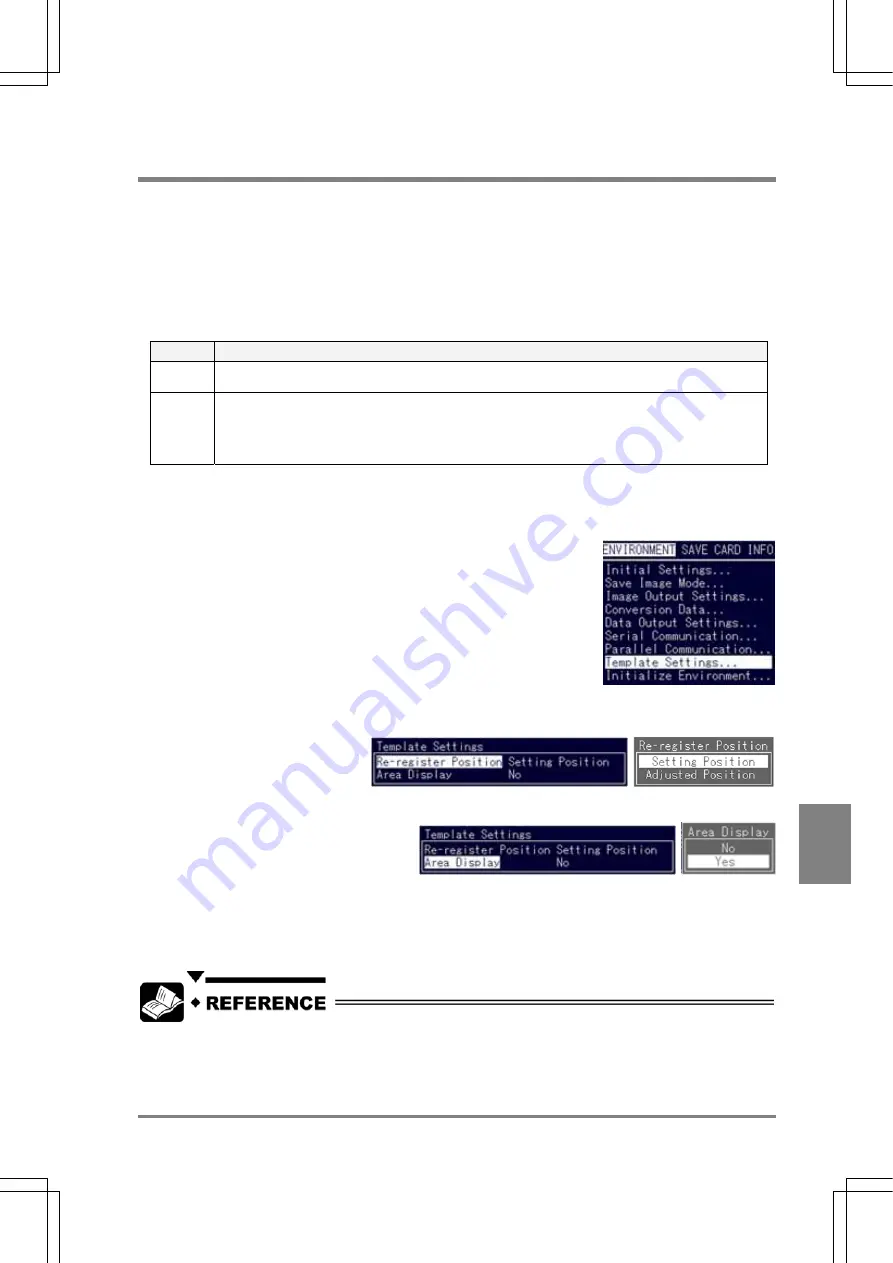
1. Select "ENVIRONMENT" > "Template Settings" from the menu bar.
2. Select "Re-register Position".
Choose "Setting Position" or "Adjusted Position". (Initial value: Setting Position)
3. Select "Area Display".
Choose "Yes" or "No". (Initial value: No)
Area Display
This is a function to check the area to be re-registered on the screen during re-registering. When using this
function, it is required to input timing signals (or commands) twice to re-register.
Re-registering by inputting parallel signal: See page 253
Re-registering by inputting serial command: See page 265
Summary of Contents for Micro-Imagechecker PV310
Page 1: ......
Page 9: ...1 Names and Functions of Parts Chapter 1 Chapter 1 Names and Functions of Parts ...
Page 22: ......
Page 23: ...15 Installation and Wiring Chapter 2 Chapter 2 Installation and Wiring ...
Page 35: ...27 Input and Output Interface Ports Chapter 3 Chapter 3 Input and Output Interface Ports ...
Page 76: ......
Page 107: ...99 Setting Checkers Chapter 6 6 7 Gray Edge 6 7 1 Menu Options ...
Page 114: ...106 Setting Checkers Chapter 6 6 8 Feature Extraction 6 8 1 Menu Options ...
Page 121: ...113 Setting Checkers Chapter 6 6 9 Smart Matching 6 9 1 Menu Options ...
Page 137: ...129 Setting Checkers Chapter 6 6 11 Flaw Detection 6 11 1 Menu Options ...
Page 207: ...199 TOOL Chapter 8 Chapter 8 TOOL ...
Page 224: ......
Page 225: ...217 Environment Settings Chapter 9 Chapter 9 Environment Settings ...
Page 249: ...241 Chapter 10 Parallel Communication Chapter 10 Parallel Communication ...
Page 265: ...257 Chapter 11 RS 232C Communication Chapter 11 RS 232C Communication ...
Page 298: ......
Page 299: ...291 Chapter 12 Ethernet Communication Chapter 12 Ethernet Communication ...
Page 303: ...295 Chapter 13 Using a Compact Flash Memory Card Chapter 13 Using a Compact Flash Memory Card ...
Page 323: ...315 Chapter 15 Troubleshooting Chapter 15 Troubleshooting ...
Page 328: ......
Page 329: ...321 Chapter 16 Camera Switching Unit Chapter 16 Camera Switching Unit ...
Page 333: ...325 Chapter 17 General Specifications Chapter 17 General Specifications ...
Page 340: ......
Page 341: ...333 Chapter 18 Product Numbers Chapter 18 Product Numbers ...
Page 347: ...339 Chapter 19 Dimensions Chapter 19 Dimensions ...
Page 349: ...341 Chapter 19 Dimensions Double Speed Random Camera C Mount ANM831 Unit mm ...
Page 352: ...344 Dimensions Chapter 19 ANM88281 ANM88081 ANM8804 ANM88161 ANM88251 Unit mm ...
Page 356: ......
Page 357: ...349 Chapter 20 Appendix Chapter 20 Appendix ...
Page 358: ...350 Appendix Chapter 20 20 1 Pin Assignment of Camera Double Speed Random Camera ANM831 ...
Page 359: ...351 Chapter 20 Appendix Standard Camera ANM832 ANM83203 ...
Page 363: ...355 Record of Changes Manual No Date Revision detail ARCT1F456E March 2009 First Edition ...


