


255
Cha
p
ter 1
0
Parallel Communicatio
n
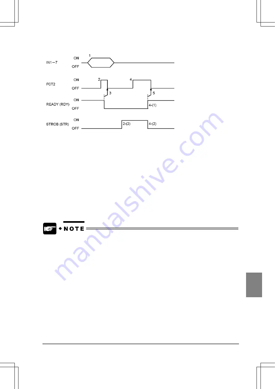
Area Display: Yes (When "Template Setting" is assigned to FCT2.)
1. Assign the numbers of the target checkers to re-register to IN1-7. (Input the data more than 1 ms
before FCT2 signal input)
2. Make sure that READY signal is on and input FCT2 signal.
(1) After READY signal is turned off, the area to be re-registered is displayed.
(2) After the area to be re-registered is displayed, STROB signal is turned on.
3. Make sure that the ready signal is off and then turn the FCT2 signal off.
4. Input the second FCT2 signal after checking the area to be re-registered on the screen monitor.
Re-registration is executed.
(1) After re-registering the template is completed, the ready signal is turned on.
(2) STROB signal is turned off upon the READY signal ON.
5. Make sure that READY signal is on (re-registration is completed) and then turn the FCT2 signal off.
•
The templates of the following checkers cannot be re-registered from the external device.
- Position Adjustment (Matching)
- Rotation Adjustment (Matching)
- Rotation Adjustment (Contour)
•
If the template cannot be re-registered nor has no features, ERROR signal will be output.
•
When a live image is displayed, a new image is re-registered after capturing the image.
•
When a memory image is displayed, the currently displayed memory image (captured last) is
re-registered.
•
If you do not want to let the PV310 lose the images after power is removed, save the current settings by
selecting "SAVE" from the menu bar or by inputting the command "%MCR" from the external device.
Summary of Contents for Micro-Imagechecker PV310
Page 1: ......
Page 9: ...1 Names and Functions of Parts Chapter 1 Chapter 1 Names and Functions of Parts ...
Page 22: ......
Page 23: ...15 Installation and Wiring Chapter 2 Chapter 2 Installation and Wiring ...
Page 35: ...27 Input and Output Interface Ports Chapter 3 Chapter 3 Input and Output Interface Ports ...
Page 76: ......
Page 107: ...99 Setting Checkers Chapter 6 6 7 Gray Edge 6 7 1 Menu Options ...
Page 114: ...106 Setting Checkers Chapter 6 6 8 Feature Extraction 6 8 1 Menu Options ...
Page 121: ...113 Setting Checkers Chapter 6 6 9 Smart Matching 6 9 1 Menu Options ...
Page 137: ...129 Setting Checkers Chapter 6 6 11 Flaw Detection 6 11 1 Menu Options ...
Page 207: ...199 TOOL Chapter 8 Chapter 8 TOOL ...
Page 224: ......
Page 225: ...217 Environment Settings Chapter 9 Chapter 9 Environment Settings ...
Page 249: ...241 Chapter 10 Parallel Communication Chapter 10 Parallel Communication ...
Page 265: ...257 Chapter 11 RS 232C Communication Chapter 11 RS 232C Communication ...
Page 298: ......
Page 299: ...291 Chapter 12 Ethernet Communication Chapter 12 Ethernet Communication ...
Page 303: ...295 Chapter 13 Using a Compact Flash Memory Card Chapter 13 Using a Compact Flash Memory Card ...
Page 323: ...315 Chapter 15 Troubleshooting Chapter 15 Troubleshooting ...
Page 328: ......
Page 329: ...321 Chapter 16 Camera Switching Unit Chapter 16 Camera Switching Unit ...
Page 333: ...325 Chapter 17 General Specifications Chapter 17 General Specifications ...
Page 340: ......
Page 341: ...333 Chapter 18 Product Numbers Chapter 18 Product Numbers ...
Page 347: ...339 Chapter 19 Dimensions Chapter 19 Dimensions ...
Page 349: ...341 Chapter 19 Dimensions Double Speed Random Camera C Mount ANM831 Unit mm ...
Page 352: ...344 Dimensions Chapter 19 ANM88281 ANM88081 ANM8804 ANM88161 ANM88251 Unit mm ...
Page 356: ......
Page 357: ...349 Chapter 20 Appendix Chapter 20 Appendix ...
Page 358: ...350 Appendix Chapter 20 20 1 Pin Assignment of Camera Double Speed Random Camera ANM831 ...
Page 359: ...351 Chapter 20 Appendix Standard Camera ANM832 ANM83203 ...
Page 363: ...355 Record of Changes Manual No Date Revision detail ARCT1F456E March 2009 First Edition ...


