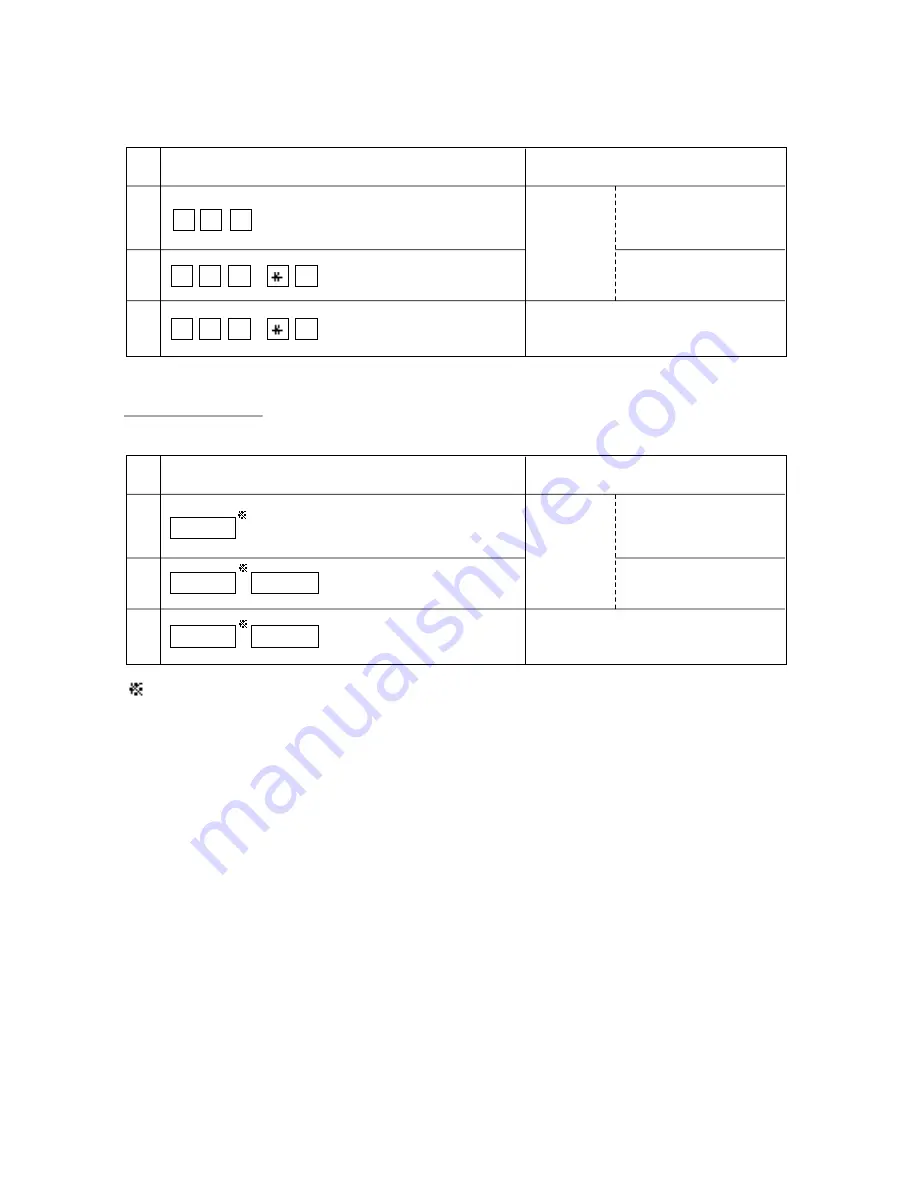
background image

SLT

Direct Trunk Access

PITS

CO buttons which belong to the trunk group 02.

1

2

3

Result

Restricted.
(Call is not
completed.)

The outside number dialed
is Restricted by “Toll
Restriction Table.”

The account code
entered is “Not valid.”

Restriction on number is overridden.
(Call is completed.)

Operation

CO button

+  [(1) + 201+] 204xxxx

CO button

+  

FWD/DND

+ 3456# + [(1) + 201+] 204xxxx

CO button

+  

FWD/DND

+ 1234# + [(1) + 201+] 204xxxx

1

2

3

Result

Restricted.
(Call is not
completed.)

The outside number dialed
is Restricted by “Toll
Restriction Table.”

The account code
entered is “Not valid.”

Restriction on number is overridden.
(Call is completed.)

3-F-61

(21292)

Operation

8     1      2   + [(1) + 201+] 204xxxx

8     1      2   +  

#

+ 3456# + [(1) + 201+] 204xxxx

8     1      2   +  

#

+ 1234# + [(1) + 201+] 204xxxx

Summary of Contents for KX-T336

Page 1: ...les Company PSC Division of Matsushita Electric of Puerto Rico Inc Ave 65 de Infantería Km 9 5 San Gabriel Industrial Park Carolina Puerto Rico 00985 Matsushita Electric of Canada Limited 5770 Ambler Drive Mississauga Ontario L4W2T3 Matsushita Electric Industrial Co Ltd Central P O Box 288 Osaka 530 91 Japan KX A220 Printed in Japan PQQX6483WA KW0691O2045 C Kyushu Matsushita Electric Co Ltd 1997 ...

Page 2: ......

Page 3: ...ompatibles Section 8 Preparation for Programming and Maintenance Dumb Type Terminal Section 9 System Programming VT220 and Compatibles Section 10 System Programming Dumb Type Terminal Section 11 System Programming Proprietary Integrated Telephone System PITS Section 12 Station Programming Proprietary Integrated Telephone System PITS Section 13 Station Programming Attendant Console ATT Section 14 M...

Page 4: ......

Page 5: ...n case of enabling the following function s please inform your telephone company of the FCC Registration number ACJJPN 18958 MF E 1 Ground Start 2 Automatic Route Selection 3 Local Access If these features are not being used use ACJJPN 18959 KF E Ringer Equivalence 0 4B Service Order Code 9 0F Facility Interface Code Loop Start 02LS2 Ground Start 02GS2 DID 02RV2 T OPX 0L13C Required Network Interf...

Page 6: ...with if such action is reasonable in the circumstances In case of such unnotified temporary discontinuance of service the Telephone Company shall a Promptly notify the customer of such temporary discontinuance of service b Afford the customer the opportunity to correct the situation which gave rise to the temporary discontinuance c Inform the customer of the right to bring a complaint to the Commi...

Page 7: ...olvents Do not use abrasive powder to clean the cabinet Wipe it with a soft cloth NOTE This equipment has been tested and found to comply with the limits for a Class A digital device pursuant to Part 15 of the FCC Rules These limits are designed to provide reasonable protection against harmful interference when the equipment is operated in a commercial environment This equipment generates uses and...

Page 8: ... 7 This product should be operated only from the type of power source indicated on the marking label If you are not sure of the type of power supply to your home consult your dealer or local power company 8 This product is equipped with a three wire grounding type plug a plug having a third grounding pin This plug will only fit into a grounding type power outlet This is a safety feature If you are...

Page 9: ...een damaged F If the product exhibits a distinct change in performance 14 Avoid using a telephone other than a cordless type during an electrical storm There may be a remote risk of electric shock from lightning 15 Do not use the telephone to report a gas leak in the vicinity of the leak SAVE THESE INSTRUCTIONS SAFETY INSTALLATION INSTRUCTIONS When installing telephone wiring basic safety precauti...

Page 10: ......

Page 11: ...Section 1 System Outline ...

Page 12: ......

Page 13: ...D 1 2 00 System Interface 1 D 1 3 00 Programming 1 D 2 4 00 Test 1 D 2 5 00 Monitor 1 D 3 6 00 Backup Utility 1 D 3 E System Configuration 1 E 1 1 00 Basic Shelf 1 E 1 2 00 Expansion Shelf 1 E 2 3 00 Attendant Console 1 E 3 4 00 CPU Card 1 E 3 5 00 TSW Card 1 E 4 6 00 Power Unit 1 E 4 7 00 LCOT Card 1 E 5 8 00 RCOT Card 1 E 5 9 00 PCOT Card 1 E 6 10 00 GCOT Card for U S A and Canada only 1 E 6 11 ...

Page 14: ... 00 RMT Card 1 E 11 21 00 T SW Conference Expansion Card 1 E 12 22 00 OHCA Card 1 E 12 23 00 T SW OHCA Expansion Card 1 E 12 24 00 OPX Power Unit 1 E 12 25 00 E M Card 1 E 13 26 00 T 1 Digital Trunk Card 1 E 13 27 00 E 1 Digital Trunk Card 1 E 14 Page ...

Page 15: ... for Programming and Operation Dumb This section describes the basic usage and command reference of Dumb terminal Section 9 System Programming VT220 and Compatibles This section provides information for the programming of the system database using VT220 and Compatibles Section 10 System Programming Dumb This section provides information for the programming of the system database using Dumb termina...

Page 16: ...ystem Class of Service Executive Busy Override Deny System Numbering Plan Busy Override Deny Set Busy Override Deny Cancel 10 C 7 00 10 C 10 00 9 D 4 01 9 D 6 04 3 shows the reference number for programming Dumb terminal user Note In this manual all reference numbers are described using Section Number Subsection Number and Title Number Example 2 00 System Administration from a Remote Location Desc...

Page 17: ...ations needs this system provides the following features Outgoing Call Features Toll Restrictions allow the manager to restrict extension users from making certain types of calls Restriction is administered through outward restriction toll restriction and ARS restriction Automatic Route Selection ARS provides for the routing of calls over the telecommunication network based on preferred routes nor...

Page 18: ...nouncement through built in speaker of Proprietary Integrated Telephone PITS and or external Pager Equipments Other Features Station Message Detail Recording SMDR generates detailed call information on all CO calls and sends this information to the printer SMDR also generates detailed data on Error Log Records System Programming Data and Traffic Information Off Premise Extension OPX allows Single ...

Page 19: ...sion of the LCOT card with the capability to detect a pay tone of CO line This is useful to charge management with a pay tone which is sent from CO line LCOT Card with Polarity Reversal Detection RCOT This card is a version of the LCOT card with the capability to detect a reversal of CO line polarity This is useful for determining the start and completion of calls Ground Start Central Office Trunk...

Page 20: ... features and is installed on the HLC card or PLC card Time Switch Off Hook Call Announcement Expansion T SW OHCA Card This card is for Off Hook Call Announcement features and is installed in the Basic Slot 2 No 1 2 3 4 5 6 7 8 9 10 11 12 13 Item HLC PLC SLC OPX DID LCOT GCOT T 1 E 1 E M PCOT RCOT DID LCOT GCOT T 1 E 1 E M PCOT RCOT DPH DISA AGC RMT ATLC HLC PLC SLC OPX DID LCOT GCOT T 1 E 1 E M P...

Page 21: ...rt Central Office Trunk Card with Polarity Reversal Detection RCOT Card Ground Start Central Office Trunk GCOT Card Proprietary ITS Line Circuit PLC Card Single Line Telephone Line Circuit SLC Card Single Line Telephone Circuit SLC Card with Message Waiting Hybrid Line Circuit HLC Card Attendant Console Line Circuit ATLC Card Direct Inward System Access DISA Card Direct Inward Dialing Trunk DID Ca...

Page 22: ...one 6 CO s Proprietary Telephone with LCD 6 CO s Proprietary Telephone 6 CO s Proprietary Telephone 12 CO s Proprietary Telephone with LCD 12 CO s Proprietary Telephone with LCD 12 CO s Proprietary Telephone with LCD 12 CO s Proprietary Telephone 12 CO s Proprietary Telephone 12 CO s Proprietary Telephone with LCD 12 CO s Proprietary Telephone 12 CO s Single Line Telephone with FLASH button Propri...

Page 23: ......

Page 24: ...1 B 2 Amplifier Paging Speaker 1 Amplifier Paging Speaker 2 Radio Radio Automobile type batteries Consisting of two 12VDC 24VDC Data Terminal Printer 2 00 System Connections 60395 To AC Outlet ...

Page 25: ...r Single Line Telephone Data Terminal one pair one pair one pair Cordless Phone one pair Telephone with Answering Machine one pair Telephone Answering System with Facsimile two pair KX T61630 KX T61640 KX T123240 two pair KX T61620 two pair KX T61650 KX T123250 two pair KX T7040 two pair two pair KX T7020 KX T123220 three pair KX T123235 KX T123230D KX T123230 two pair Parallel connections of exte...

Page 26: ...s Phone Telephone with Answering Machine Telephone Answering System with Facsimile SLC KX T96174 RMT KX T96196 AGC KX T96193 DISA KX T96191 Single Line Telephone Data Terminal Cordless Phone Telephone Answering System with Facsimile Telephone with Answering Machine Doorphone 1 Doorphone 2 Doorphone 3 Doorphone 4 DPH KX T96161 Attendant Console KX T96300 Attendant Console KX T96300 A 26D BATT 24V P...

Page 27: ...inctive Busy Tone Confirmation Tone Tone and Ringing Patterns Toll Restriction for Local Trunk Dial Access Toll Restriction in ARS System Toll Restriction for Individual Trunk Group Dial Access Direct Trunk Access Toll Restriction for Individual Virtual Trunk Group Dial Access Operator International Call Restriction 7 10 Digit Toll Restriction Toll Restriction for Speed Dialing Automatic Route Sel...

Page 28: ... Message Detail Recording SMDR Off Premise Extension OPX Walking Station Outgoing Message OGM Recording and Playing Back Intercept Routing No Answer Rerouting Calling Party Control CPC Detection CO Busy Out Parallel Connection of Extensions Voice Mail Integration DTMF Tone Integration Continued ...

Page 29: ...g Intercom Busy Station Signaling Off Hook Call Announcement OHCA Automatic Callback Busy Trunk Station Executive Busy Override Do Not Disturb DND Override Walking COS Class of Service Operator Call On Hook Dialing Speed Dialing System Speed Dialing Station One Touch Dialing Last Number Redial LNR Saved Number Redial SNR Automatic Redial Pickup Dialing Serial Call Line Selection Answering Direct A...

Page 30: ...No Answer to Trunk Heavy Traffic Overflow Transfer to Station Camp on to Station Interposition Call Transfer Call Transfer via Attendant Console Released Link Operation Programmable Privacy Privacy Release Privacy Attach Hands Free Operation Conference Unattended Conference Doorphone Flash External Feature Access Microphone Mute Off Hook Call Announcement OHCA Tone Through End to End DTMF Signalin...

Page 31: ...et Dialing Assigned Feature Clear Electronic Station Lock Out Remote Station Feature Control Absent Message Capability Message Waiting Data Line Security DSS Console features Automatic Transfer Dial Tone Transfer CO Access Control Search by Name Department OGM Recording and Playing Back Power Failure Operation Trunk Verify Features PITS SLT ATT Continued ...

Page 32: ... can be accessed either locally or remotely using the system RS 232C interface The system may be configured for local direct access from the data terminal or via a modem connection that allows the data terminal to be located at a greater distance from the system than is allowed for an RS 232C interface For remote access a data terminal and modem are required at the maintenance location and the RMT...

Page 33: ...nostics in fault diagnosis and corrective maintenance are described in Section 14 Maintenance VT220 and Compatibles and Section 15 Maintenance Dumb Self Test System Detected Troubles System s built in on line diagnostic test program monitors the troubles generated by hardware or software during on line communication mode VT220 and Compatibles user Refer to Section 14 D Self Test System Detected Tr...

Page 34: ... individually Station Trunk Group Attendant Console DISA OGM1 OGM2 AGC Refer to Section 14 G Monitor for further information about monitor 6 00 Backup Utility Making backups of the system programming data and keeping it is extremely important in the unlikely event that system programming data are lost in a system failure Backup Utility consists of save and load Save is to transmit a file of data f...

Page 35: ...card Free Slot can be equipped with the following optional service cards a Loop start central office trunk LCOT Card b Loop start central office trunk with Pay Tone Detection PCOT Card c Loop start central office trunk with Polarity Reversal Detection RCOT Card d Ground start central office trunk GCOT Card e Hybrid line circuit HLC Card f Proprietary ITS Line circuit PLC Card g Single line telepho...

Page 36: ...service cards a Loop start central office trunk LCOT Card b Loop start central office trunk with Pay Tone Detection PCOT Card c Loop start central office trunk with Polarity Reversal Detection RCOT Card d Ground start central office trunk GCOT Card e Hybrid line circuit HLC Card f Proprietary ITS Line circuit PLC Card g Single line telephone line circuit SLC Card h Single line telephone line circu...

Page 37: ...r the following Call Processing mode System programming Diagnostics Editing local data 4 00 CPU Card Functions 1 Call process and basic shelf main protocol Microprocessor 80C286 Time switch TSW control detection of system clock alarm basic shelf power down and expansion shelf power down alarm watch dog 2 System switch interface There are Operation Switch MODE 10 modes 0 to 9 and System Administrat...

Page 38: ... each amp circuit is equipped with a knob 6 Music in interface T SW card has 2 interface circuits for music on hold or BGM Operation 1 A knob for adjusting volume of external paging is turned with a screw driver from front of T SW card 2 LED indicator or the T SW card lights when system reset or T SW local reset occurs 6 00 Power Unit Functions 1 Power supply 5 15 GND for a shelf 2 External batter...

Page 39: ...cator on the LCOT card lights when the system reset or LCOT local reset occurs 1 E 5 70695 8 00 RCOT Card Functions RCOT KX T96183 Loop Start Central Office Trunk with Polarity Reversal Detection card 8 CO Lines card 1 Loop start CO interface CPC detection 1 DTMF driver With loop start you seize a line by bridging through a resistance the tip and ring both wires of your telephone line 2 Power fail...

Page 40: ...dicator on the PCOT card lights when the system reset or PCOT local reset occurs 1 E 6 70695 10 00 GCOT Card for U S A and Canada only Functions GCOT KX T96181 Ground Start Central Office Trunk card 8 CO Lines card 1 Ground start CO interface CPC detection 1 DTMF driver A way of signaling on subscriber trunks in which one side of the two wire trunk typically the Ring conductor of the Tip and Ring ...

Page 41: ...tance 600 ohms including SLT Power supply 30V with current limitation circuit 2 DTMF receivers dial pulse detector 2 Power Failure Transfer PFT by ports 1 through 8 When power failure occurs SLT Tip Ring are led by a PFT relay but SLT PFT modular and LCOT GCOT modular should be connected each other by connection cords in advance 3 ports are available for KX T96174X 3 Diagnostic transfer DT by each...

Page 42: ... of SLT card 2 PITS and DSS console interface PITS and DSS console interface is quite same as that of PLC card 3 Interface for PITS KX T123230D KX T123235 KX T7130 with OHCA feature Interface for PITS KX T123230D KX T123235 KX T7130 with OHCA feature is quite same as that of PLC 4 Power failure transfer by each port when using SLT Power failure transfer is quite same as that of SLC card 5 Diagnost...

Page 43: ... 1 DID Direct Inward Dialing card KX T96182 Wink start immediate start DID interface 4 circuits card 45V used in circuits is originated from DC DC converter in DID card DID card will receive pulse signal only 2 Both way DID card KX T96182D Wink start immediate start DID interface 4 circuits card a Incoming 45V used in circuit is originated from DC DC converter in DID card Signaling Pulse DTMF b Ou...

Page 44: ...hones can be connected using a modular connector Doorphone chime is sent to both extension and doorphone at a time when a doorphone button is pressed 2 Door opener interface 4 circuits card DPH card has 4 relays for door opener 120VAC 1A The relay opens for doorlock closes for door release It also opens in the case of power failure Operation Terminal plate on the DPH card has 8 terminals 2 leads f...

Page 45: ... CO CO speech path 2 4 DTMF transceivers DTMF transceiver is used as DTMF repeater So AGC card microprocessor controls DTMF repeater 3 8 Speech End Detectors Speech end detector of AGC is quite same as that of DISA card Operation LED indicator on the AGC card lights when the system reset or AGC local reset occurs 20 00 RMT Card Functions RMT Remote Circuit card KX T96196 Modem 300 1200 bps for rem...

Page 46: ...nother extension that is in conversation using the handset This feature is available only against the following PITS telephones KX T123230D KX T123235 KX T7130 23 00 T SW OHCA Expansion Card Functions T SW OHCA Expansion card KX T336105 This card is mounted on Basic Slot 2 for OHCA feature OHCA card KX T96136 for extension port must be installed on the HLC card or PLC card in advance 24 00 OPX Pow...

Page 47: ...tery 48 VDC 20 mA to ground max Sensitivity 5 mA or 2000 Ω to min ground max 6 M lead Permitted current 30mA max Permitted voltage _100V max 26 00 T 1 Digital Trunk Card Functions T 1 interface 1 circuit card T 1 is a digital transmission link with a capacity of 1 544 Mbps A T 1 card carries 24 voice conversations Frame Format D4 ESF Line Coding AMI B8ZS Channel Type LCO GCO DID OPX TIE Signaling ...

Page 48: ... card carries 30 voice conversations Frame Format PCM30 PCM30 CRC Line Coding HDB3 AMI Channel Type DR2 E M C E M P Signaling DP DTMF MFC R2 DTMF 8 receivers and 2 generators MFC R2 16 receivers and 16 generators Operation RED LED indicator on E 1 card lights when the system reset or E 1 card local reset E 1 line fault occurs 1 E 14 70695 ...

Page 49: ...Section 2 Installation ...

Page 50: ......

Page 51: ...3 02 Installation of Top Cover 2 B 15 3 03 Cable Connections 2 B 16 4 00 Ground Wiring 2 B 18 5 00 Fixing on the Floor 2 B 19 5 01 Setting Out and Drilling 2 B 19 5 02 Fixing on the Floor 2 B 22 C Installation of Cards 2 C 1 1 00 Before Installation 2 C 1 1 01 Slot Construction 2 C 1 1 02 Guide Plate 2 C 2 2 00 Connection of Standard System 2 C 3 2 01 CPU Card 2 C 3 2 02 T SW Card 2 C 3 2 03 Power...

Page 52: ...r areas other than U S A and Canada 4 00 Parallel Connection of the Extensions 2 C 29 5 00 Auxiliary Connection for Power Failure Transfer 2 C 30 6 00 Connection of the Battery Adaptor KX A26D 2 C 32 D Connection of Optional Peripheral Equipments 2 D 1 1 00 Paging Equipment 2 D 1 2 00 External Music Source 2 D 2 3 00 RS 232C Interface 2 D 3 3 01 Connection to the Printer 2 D 5 3 02 Connection to t...

Page 53: ...wer Up Procedure 2 F 1 2 00 CPU Rotary Switch Features 2 F 2 2 01 Operation Switch MODE 2 F 2 2 02 System Administration Device Selection Switch SYSTEM 2 F 5 2 03 Operation Sequence for System Starting Up 2 F 6 2 3 70695 ...

Page 54: ......

Page 55: ...ed to install the KX T336 System Detailed instructions for planning the installation site installing the shelves and optional cards and cabling of peripheral equipments are provided Further information on system expansion and peripheral equipment installation is included 2 A 1 ...

Page 56: ...asons of maintenance and inspection be especially careful to allow space for cooling above and at the sides of the KX T336 system 2 Wiring Cautions Make sure to keep the following instructions when wiring 1 Do not wire the telephone cable in parallel with an AC power source computer telex etc If the cables are run near those wires shield the cables with metal tubing or use shielded cables and grou...

Page 57: ...nstalled to the system Each expansion shelf can be equipped with up to 120 lines including Extensions and CO lines The system can consist of one two or three shelves Basic Expansion 1 and Expansion 2 Each shelf contains its own power supply 1 00 Basic Shelf Basic Shelf is always required and it can be equipped with up to 96 lines including Extension and CO lines The basic shelf includes top cover ...

Page 58: ...Supply Cable Connector 12 Main Power Switch Turns ON and OFF the Power of Whole Unit 13 Ground Wire Connector GND 14 Base Front Panel 15 LED Cable 16 LED Cable Connector Connects the LED Cable 17 Side Panel Right 18 Flat Cable Connector Connects the Flat Cable from Expansion Shelf 19 Cable Opening 20 Base Board 21 Battery Adaptor Compartment 1 01 Basic Shelf Assembly Top Cover Basic Shelf Base She...

Page 59: ...se to unlock 2 Open the front panel toward you at right angles to the basic shelf 3 Remove the front panel by lifting it straight up Base Front Panel 1 2 1 Open the base front panel toward you while holding down the button on the panel 2 Pull out the base front panel to the right 3 2 2 B 3 ...

Page 60: ...per left side panel by loosening the four screws Screws Screws Screws Screws Base Side Panel 1 Remove the lower left side panel by loosening the four screws Note If the system is to be expanded to 2 Shelf System proceed to Section 2 B 2 00 Expansion to 2 Shelf System Screws Screws 2 B 4 ...

Page 61: ...lug the LED cable on the top cover into the LED cable connector on the basic shelf Power Supply Cable power supply cable Plug the power supply cable on the basic shelf into the power supply cable connector labeled AC OUT 1 on the base shelf 2 B 5 ...

Page 62: ...ded to 2 Shelf System by installing the Expansion Shelf 1 on the Basic Shelf The 2 Shelf system can be equipped with up to 216 lines including extensions and CO lines The following figure shows a 2 Shelf System composed of a basic shelf and an expansion shelf 2 B 6 ...

Page 63: ...ector Connects the Battery Adaptor Cable 6 Fuse 7 Power Supply Cable 8 Front Panel 9 LED Cable Connector Connects the LED Cable 10 Side Panel Right 11 Flat Cable 12 Cable Opening 2 01 Expansion Shelf Assembly 1 2 3 4 5 6 7 8 9 10 11 12 Note The construction of Expansion Shelf 1 and Expansion Shelf 2 is identical to each other 2 B 7 ...

Page 64: ...elf Removing the Top Cover 1 LED cable LED cable connector Screws Screws 2 1 Disconnect the LED cable on the top cover from the LED cable connector on the basic shelf 2 Remove the top cover by loosening the four screws Top cover 2 B 8 ...

Page 65: ...anel by loosening the four screws Screws Screws Screws Screws Guides 2 B 9 Expansion Shelf Front Panel 1 Rotate the key on the front panel counterclockwise to unlock 2 Open the front panel toward you at right angles to the expansion shelf 3 Remove the front panel by lifting it straight up 1 3 2 ...

Page 66: ...holes of the expansion shelf exactly on the holes of the basic shelf 2 When the holes are placed properly fix them with the three screws immediately to prevent the expansion shelf from falling down Screws Note If the system is to be expanded to 3 Shelf System proceed to Section 2 B 3 00 Expansion to 3 Shelf System 2 B 10 ...

Page 67: ...sion shelf Note Before installing the top cover remove a screw as shown in the illustration above Otherwise the top cover cannot be installed properly This screw is necessary for installing an expansion shelf 2 When the holes are placed properly fix them with the four screws immediately to prevent the top cover from falling down Screws Screws 2 B 11 ...

Page 68: ...lug the LED cable on the top cover into the LED cable connector on the expansion shelf 2 Plug the flat cable on the expansion shelf into the flat cable connector on the basic shelf Power Supply Cable Plug the power supply cable into the power supply cable connector AC OUT 2 Top cover Expansion shelf Basic shelf Base shelf Power supply cable 2 B 12 ...

Page 69: ...g extensions and CO lines can be equipped with 3 Shelf System Note Before stacking the Expansion Shelf 2 on the 2 Shelf System remove the front panel and side panels from Expansion Shelf 2 following the procedures described in Section 2 B 2 00 Expansion to 2 Shelf System The figure below shows a 3 Shelf System composed of a basic shelf and two expansion shelves 2 B 13 ...

Page 70: ...Shelf System place the holes of the expansion shelf 2 exactly on the holes of the expansion shelf 1 2 Screws When the holes are placed properly fix them with the three screws immediately to prevent the expansion shelf 2 from falling down 3 01 Stacking on the 2 Shelf System 2 B 14 ...

Page 71: ...he holes of the top cover exactly on the holes of the expansion shelf 2 2 Screws Screws When the holes are placed properly fix them with the four screws immediately to prevent the top cover from falling down 3 02 Installation of Top Cover 2 B 15 ...

Page 72: ...able LED cable Flat cable Flat cable connector 1 Plug the LED cable on the top cover into the LED cable connector on the expansion shelf 2 2 Plug the flat cable on the expansion shelf 2 into the flat cable connector on the basic shelf 2 B 16 ...

Page 73: ...Supply Cable Plug the power supply cable on the Expansion Shelf 2 into the power supply cable connector AC OUT 3 Top cover Expansion shelf 2 Expansion shelf 1 Basic shelf Base shelf Power supply cable 2 B 17 ...

Page 74: ...4 00 Ground Wiring IMPORTANT Make sure to connect the frame of the KX T336 system to the earth ground properly to protect the unit Connect the ground wire to the ground wire connector GND 2 B 18 ...

Page 75: ...e hole Note When fixing the KX T336 System to the floor anchor plugs should always be used to prevent the system from falling down Hammer Hole Anchor plug 1 4 32 inch 8 32 inch 5 00 Fixing on the Floor 5 01 Setting Out and Drilling 1 Basic System Basic Shelf 14 31 32 1 3 8 12 14 32 A 10 10 32 11 12 32 2 4 32 2 4 32 1 10 32 13 5 32 2 2 32 2 B 19 ...

Page 76: ...chor plug into the hole Note When fixing the KX T336 System to the floor anchor plugs should always be used to prevent the system from falling down Hammer Hole Anchor plug 1 4 32 inch 8 32 inch 2 2 Shelf System Basic Shelf Expansion Shelf 1 26 25 32 1 3 8 12 14 32 A 10 10 32 11 12 32 2 4 32 2 4 32 1 10 32 13 5 32 2 2 32 2 B 20 ...

Page 77: ...r plug on the floor in accordance with the measurements Drive the anchor plug into the hole Note When fixing the KX T336 System to the floor anchor plugs should always be used to prevent the system from falling down Hammer Hole Anchor plug 1 4 32 inch 8 32 inch 12 14 32 A 10 10 32 11 12 32 2 4 32 2 4 32 1 10 32 13 5 32 2 2 32 2 B 21 ...

Page 78: ...s to the basic shelf as shown in the figure Fasten each hardware with four screws 3 Fix the shelf securely to the floor using screws and flat washers Latch Hole Washer Screw Anchor plug 2 Position the shelf on the floor Check alignment and level of the shelf 2 B 22 ...

Page 79: ... S 1 F S 2 F S 3 F S 4 F S 5 F S 6 F S 7 F S 8 F S 9 F S 10 F S 11 F S 12 B S 1 B S 2 B S 3 Basic shelf Expansion shelf 1 Expansion shelf 2 Name POWER for Power Unit BS1 Basic Slot 1 for CPU card BS2 Basic Slot 2 for optional T SW OHCA card BS3 Basic Slot 3 for T SW card FS1 to 12 Free Slot 1 to 12 for optional service card Number 1 1 1 1 12 No 1 2 3 4 5 Basic shelf Expansion shelf 1 Expansion she...

Page 80: ...h facing the components side to the right along with the upper and lower guide rails Press the upper and lower latch firmly until the upper latch is located inside of the shelf See Fig 2 and Fig 3 Please do not touch the components side of the service card 3 After installing the service cards attach the Guide Plate to the upper front side of the basic shelf and expansion shelf 1 and 2 if provided ...

Page 81: ... already inserted at the factory in the TSW in the Basic shelf 2 C 3 60395 Music source Selector Switch TSW MUS 2 This card is already inserted at the factory in the TSW in the Basic shelf Music Source Selector Switch INT MUS Set when using the internal music source MUS 2 Set when using the external music source INT MUS for U S A and Canada for areas other than U S A and Canada TSW is marked ...

Page 82: ...2 03 Power Unit Power unit is already inserted at the factory in the POWER in the Basic shelf and the Expansion shelf 1 2 2 C 3 1 60395 ...

Page 83: ......

Page 84: ... card 1 Connection to the T SW card 30 pin connector Plug Make sure the card is in the correct direction 30 pin connector Jack T SW Card KX T336104 TSW CONF T SW Conference Card 1 Insert the 30 pin connector plug on the T SW CONF card into the 30 pin connector jack on the T SW card 2 Install the T SW card into the Basic Slot 1 BS1 See page 2 C 3 2 C 4 ...

Page 85: ...3 02 T SW OHCA Card KX T336105 OHCA is marked Insert this card into the Basic Slot 2 BS2 OHCA 2 C 5 ...

Page 86: ...ds 2 Insert the connector plug on the OHCA card into the connector jack on the HLC card 3 Install the HLC card into a free slot See page 2 C 14 Two extensions are available for the OHCA function with one OHCA card Refer to page 2 C 8 The OHCA function is provided with the following PITS telephones only KX T123235 KX T123230D or KX T7130 9 pin connector plug 5 pin connector plug 4 pin connector plu...

Page 87: ...k on the PLC card 3 Install the PLC card to a free slot See page 2 C 16 Two extensions are available for the OHCA function with one OHCA card Refer to page 2 C 8 The OHCA function is provided with the following PITS telephones only KX T123235 KX T123230D or KX T7130 5 pin connector plug 9 pin connector plug 4 pin connector plug 5 pin connector jack 9 pin connector jack 4 pin connector jack 2 C 7 ...

Page 88: ...LU BLK BLK ORN ORN BLK BLK GRN GRN BLK BLK BRN BRN BLK BLK SLT SLT BLK YEL BLU BLU YEL YEL ORN ORN YEL YEL GRN GRN YEL YEL BRN BRN YEL YEL SLT SLT YEL VIO BLU BLU VIO VIO ORN ORN VIO VIO GRN GRN VIO VIO BRN BRN VIO VIO SLT SLT VIO CLIP NO 1 2 3 4 5 6 7 8 9 10 11 12 13 14 15 16 17 18 19 20 21 22 23 24 25 26 27 28 29 30 31 32 33 34 35 36 37 38 39 40 41 42 43 44 45 46 47 48 49 50 NO 1 NO 2 NO 3 NO 4 ...

Page 89: ...ne cord 2 conductor wiring 26 AWG Under 680 feet 24 AWG Under 1130 feet 22 AWG Under 1770 feet 2 Connection to the Attendant Console KX T96300 Use 2 conductor wiring cord ATLC Card KX T96141 Insert the modular plug of the Attendant Console line cord 2 conductor wiring into the modular jack on the ATLC card Attendant Console KX T96300 2 C 9 ...

Page 90: ...lot 3 05 DPH Card KX T96161 1 Maximum cabling distance of the Doorphone and the Door Opener line 26 AWG Under 230 feet 24 AWG Under 370 feet 22 AWG Under 590 feet 26 AWG Under 230 feet 24 AWG Under 370 feet 22 AWG Under 590 feet Door Opener Doorphone 2 C 10 ...

Page 91: ...ccording to your wall type See the following 2 Installation of the Doorphone KX T30865 When the doorphone plate has been fixed to the wall When you wish to install the doorphone directly to the wall 3 Connect the wires from the terminal box to the screws located in the front cover 4 Secure both halves together and re install the screw To the terminal box See page 2 C 12 2 C 11 ...

Page 92: ... 1 4 Connect the wires of doorphone 3 to the red and green screws of the terminal box 2 5 Connect the wires of doorphone 4 to the yellow and black screws of the terminal box 2 3 Wiring of the Doorphone Terminal Box 1 YELLOW RED YELLOW RED BLACK GREEN BLACK GREEN Terminal Box 2 Doorphone 1 KX T30865 4 conductor wiring is required 4 conductor wiring is required Doorphone 3 KX T30865 Doorphone 4 KX T...

Page 93: ...ener 2 doorphone 3 door opener 3 doorphone 4 door opener 4 Paired Paired Paired Paired Set the door opener paired with the doorphone Only the telephone which received the doorphone call and in conversation can open the door using door opener System program determines the telephones that can receive the doorphone calls and use the door opener 2 C 13 ...

Page 94: ...n line cord Connector type 50 pin Amphenol 57JE series or the equivalent To Extensions Insert the 50 pin connector plug of the extension line cord into the 50 pin connector jack on the HLC card Refer to the Installation of the Amphenol 57JE series on page 2 C 24 2 Connection of cable pins See page 2 C 20 2 C 14 ...

Page 95: ...ietary Telephone Single Line Telephone 26 AWG Under 460 feet 24 AWG Under 750 feet 22 AWG Under 1180 feet 26 AWG Under 460 feet 24 AWG Under 750 feet 22 AWG Under 1180 feet 26 AWG Under 2290 feet 24 AWG Under 3700 feet 22 AWG Under 5900 feet 4 Auxiliary connection See page 2 C 30 2 C 15 ...

Page 96: ...plug of the extension line cord into the 50 pin connector jack on the PLC card Refer to the Installation of the Amphenol 57JE series on page 2 C 24 2 Connection of cable pins See page 2 C 20 1 Connection of the extension line cord Connector type 50 pin Amphenol 57JE series or the equivalent To Extensions 2 C 16 ...

Page 97: ...stance of the extension line cord twisted cable DSS Console 26 AWG Under 460 feet 24 AWG Under 750 feet 22 AWG Under 1180 feet 26 AWG Under 460 feet 24 AWG Under 750 feet 22 AWG Under 1180 feet Proprietary Telephone 2 C 17 ...

Page 98: ...plug of the extension line cord into the 50 pin connector jack on the SLC card Refer to the Installation of the Amphenol 57JE series on page 2 C 24 2 Connection of cable pins See page 2 C 20 1 Connection of the extension line cord Connector type 50 pin Amphenol 57JE series or the equivalent To Extensions 2 C 18 ...

Page 99: ... Maximum cabling distance of the extension line cord twisted cable Single Line Telephone 26 AWG Under 2290 feet 24 AWG Under 3700 feet 22 AWG Under 5900 feet 4 Auxiliary connection See page 2 C 30 2 C 19 ...

Page 100: ...5 CABLE COLOR WHT BLU BLU WHT WHT ORN ORN WHT WHT GRN GRN WHT WHT BRN BRN WHT WHT SLT SLT WHT RED BLU BLU RED RED ORN ORN RED RED GRN GRN RED RED BRN BRN RED RED SLT SLT RED BLK BLU BLU BLK BLK ORN ORN BLK BLK GRN GRN BLK BLK BRN BRN BLK BLK SLT SLT BLK YEL BLU BLU YEL YEL ORN ORN YEL YEL GRN GRN YEL YEL BRN BRN YEL YEL SLT SLT YEL VIO BLU BLU VIO VIO ORN ORN VIO VIO GRN GRN VIO VIO BRN BRN VIO VI...

Page 101: ...A204 Cable to KX A205 Clip Terminal as follows Refer to the connection chart on page 2 C 22 The KX A204 205 consists of the following KX A204 Cable 1 KX A205 Clip Terminal 1 Extension Connection of KX A204 Cable KX A205 Clip Terminal HLC Card KX T96170 or PLC Card KX T96172 or SLC Card KX T96174 Connector type 50 pin Amphenol 57JE series or the equivalent KX A204 Cable 2 C 20 1 X 60395 ...

Page 102: ...5 Cable Color ORN RED ORN BLK YEL RED YEL BLK GRN RED GRN BLK GRY RED GRY BLK WHT RED WHT BLK ORN RED ORN BLK YEL RED YEL BLK GRN RED GRN BLK GRY RED GRY BLK WHT RED WHT BLK ORN RED ORN BLK YEL RED YEL BLK GRN RED GRN BLK GRY RED GRY BLK WHT RED WHT BLK ORN RED ORN BLK YEL RED YEL BLK GRN RED GRN BLK GRY RED GRY BLK WHT RED WHT BLK ORN RED ORN BLK YEL RED YEL BLK GRN RED GRN BLK GRY RED GRY BLK WH...

Page 103: ...o the 50 pin connector jack on the LCOT card Refer to the Installation of the Amphenol 57JE series on page 2 C 24 2 Connection of cable pins See page 2 C 23 3 Auxiliary connection See page 2 C 30 1 Connection of the Central Office Line cord twisted cable To Terminal Board from the Central Office CO Connector type 50 pin Amphenol 57JE series or the equivalent 2 C 21 ...

Page 104: ...o the 50 pin connector jack on the GCOT card Refer to the Installation of the Amphenol 57JE series on page 2 C 24 2 Connection of cable pins See page 2 C 23 3 Auxiliary connection See page 2 C 30 1 Connection of the Central Office Line cord twisted cable To Terminal Board from the Central Office CO Connector type 50 pin Amphenol 57JE series or the equivalent 2 C 22 ...

Page 105: ...BLK BLU BLU BLK BLK ORN ORN BLK BLK GRN GRN BLK BLK BRN BRN BLK BLK SLT SLT BLK YEL BLU BLU YEL YEL ORN ORN YEL YEL GRN GRN YEL YEL BRN BRN YEL YEL SLT SLT YEL VIO BLU BLU VIO VIO ORN ORN VIO VIO GRN GRN VIO VIO BRN BRN VIO VIO SLT SLT VIO CLIP NO 1 2 3 4 5 6 7 8 9 10 11 12 13 14 15 16 17 18 19 20 21 22 23 24 25 26 27 28 29 30 31 32 33 34 35 36 37 38 39 40 41 42 43 44 45 46 47 48 49 50 NO 1 NO 2 N...

Page 106: ...fer to the connection chart on page 2 C 26 The KX A204 205 consists of the following KX A204 Cable one KX A205 Clip Terminal one Central Office Line Connection of KX A204 Cable KX A205 Clip Terminal 2 C 23 1 X 60395 LCOT Card KX T96180 Connector type 50 pin Amphenol 57JE series or the equivalent KX A204 Cable To Terminal Board from the Central Office CO ...

Page 107: ...D YEL BLK GRN RED GRN BLK GRY RED GRY BLK WHT RED WHT BLK ORN RED ORN BLK YEL RED YEL BLK GRN RED GRN BLK GRY RED GRY BLK WHT RED WHT BLK ORN RED ORN BLK YEL RED YEL BLK GRN RED GRN BLK GRY RED GRY BLK WHT RED WHT BLK Clip No 1 2 3 4 5 6 7 8 9 10 11 12 13 14 15 16 17 18 19 20 21 22 23 24 25 26 27 28 29 30 31 32 33 34 35 36 37 38 39 40 41 42 43 44 45 46 47 48 49 50 Number of Dot 1 1 1 1 1 1 1 1 1 1...

Page 108: ...jack on the Option Card has two hook pins Remove the upper hook pin taking out the screw 2 To attach the Amphenol 57JE type plug to the connector drive the accessory Screw at the upper part and fasten the accessory Wire Tie around the lower hook pin and the Amphenol 57JE type as shown Option Card Screw Hook pins 50 pin connector 2 C 24 ...

Page 109: ... 4 only 3 11 DID Card 1 DID Card KX T96182 for U S A and Canada DID is marked KX T96182 Insert this card into a free slot Insert the modular plug of the telephone line cord 2 conductor wiring into the modular jack on the DID card Note The DID port No 4 is equipped with H High and L Low leads If you connect a 4 conductor wiring cord to this port the on off status of the system can be detected throu...

Page 110: ...uctor wiring cord DID Card KX T96182 A A wire B B wire View of TEL Jack CO 3 11 DID Card 2 DID Card KX T96182 for areas other than U S A and Canada DID is marked KX T96182 Insert this card into a free slot The DID port No 4 is equipped with H and L leads as well as A wire and B wire However please be sure to use 2 conductor wiring cord for connection Make sure to connect the frame of the KX T336 S...

Page 111: ...R Ring T Tip R T View of TEL Jack CO 3 11 DID Card 3 Both way DID Card KX T96182D for areas other than U S A and Canada DID 2W is marked KX T96182D Insert this card into a free slot Note Make sure to match the polarity of DID lines and DID port Ring negative Tip positive The DID ports 1 through 4 are equipped with H High and L Low leads in addition to R and T However please be sure to use 2 conduc...

Page 112: ... T96182CE T Tip R Ring T R View of TEL Jack CO 3 11 DID Card 4 MFC DID Card KX T96182CE for areas other than U S A and Canada DID MFC is marked KX T96182CE Insert this card into a free slot Note Make sure to match the polarity of DID lines and DID port Ring negative Tip positive The DID ports 1 through 4 are equipped with H High and L Low leads in addition to R and T However please be sure to use ...

Page 113: ......

Page 114: ...ng into the modular jack on the OPX card 22 AWG Under 6 miles Use 2 conductor wiring cord OPX Card Single Line Telephone OPX Port No 1 OPX Port No 2 OPX Port No 3 OPX Port No 4 2 Connection to public lines Insert the modular plug of the Single Line Telephone Line cord 2 conductor wiring into the modular jack on the OPX card Use 2 conductor wiring cord OPX Card OPX Central Office Line 2 C 26 ...

Page 115: ...186 screw 1 Insert the 9 pin connector plug of the OPX Power Unit into the 9 pin connector jack on the OPX card 2 Connect the frame of the OPX Power Unit to earth ground properly to protect the unit 3 Plug the AC Power cord of the OPX Power Unit to the AC outlet 4 Turn on the Power Switch on the OPX Power Unit The Power indicator will be lit 2 C 27 60395 for U S A and Canada ...

Page 116: ...3 Check the Voltage Selector if it is set to your household AC voltage If not reset the Voltage Selector to the correct position with a screwdriver There is no Voltage Selector for some countries The correct voltage is already set 4 Plug in the AC Power cord from the OPX Power Unit 5 Turn on the Power Switch on the OPX Power Unit The Power indicator will be lit Primary Power Fuse If the Power Indi...

Page 117: ......

Page 118: ...ISA is marked KX T96191 Insert this card into a free slot 3 14 AGC Card KX T96193 AGC is marked KX T96193 Insert this card into a free slot 3 15 RMT Card KX T96196 RMT is marked KX T96196 Insert this card into a free slot 2 C 28 ...

Page 119: ...ine Connector type 50 pin Amphenol 57JE series or the equivalent Connect the ground wire to the ground wire connector GND Insert the 50 pin connector plug of the E M Line cord twisted cable into the 50 pin connector jack on the E M card Refer to the Installation of the Amphenol 57JE series on page 2 C 24 2 Connection of cable pins See pages 2 C 28 2 and 2 C 28 3 PUSH ...

Page 120: ...or 4 wire send R T1 4 wire receive R1 E Lead SG Lead SB Lead M1 Lead No connect M Lead only for Type 5 E M Line NO 1 NO 2 NO 3 NO 4 1 1 1 1 1 1 1 1 1 1 2 2 2 2 2 2 2 2 2 2 3 3 3 3 3 3 3 3 3 3 4 4 4 4 4 4 4 4 4 4 1 2 3 4 5 6 7 8 9 10 11 12 13 14 15 16 17 18 19 20 21 22 23 24 25 26 27 28 29 30 31 32 33 34 35 36 37 38 39 40 Clip No ORN RED ORN BLK YEL RED YEL BLK GRY RED GRY BLK WHY RED WHY BLK ORN R...

Page 121: ...2 C 28 3 70695 Cable Pin Numbers to be connected E M Line E M Line Wiring 50 pin Connector Block Terminal E M Line 1 Bridging Clips ...

Page 122: ... T336 system KX T96184 2 wire voice path 4 wire voice path KX T96184 Another KX T96184 KX T96184 Another KX T96184 Connection to E M Central Office 2 wire voice path KX T96184 E M Central Office 4 wire voice path KX T96184 E M Central Office ...

Page 123: ...Please connect KX A204 Cable to KX A205 Clip Terminal as follows Refer to the connection chart on page 2 C 28 6 KX A205 Clip Terminal The KX A204 205 consists of the following KX A204 Cable one KX A205 Clip Terminal one To Terminal Board from the E M Line KX A204 Cable Connector type 50 pin Amphenol 57JE series or the equivalent E M Card KX T96184 ...

Page 124: ...RY BLK WHY RED WHY BLK ORN RED ORN BLK YEL RED YEL BLK GRY RED GRY BLK WHY RED WHY BLK 1 26 2 27 3 28 4 29 5 30 6 31 7 32 8 33 9 34 10 35 11 36 12 37 13 38 14 39 15 40 16 41 17 42 18 43 19 44 20 45 Note 21 25 46 50 No connect Clip No Cable Color Number of Dot E M Line T 2 wire or 4 wire send R T1 4 wire receive R1 E Lead SG Lead SB Lead M1 Lead No connect M Lead only for Type 5 T 2 wire or 4 wire ...

Page 125: ...M sequences using the hard switch on the KX T96184 Hard switch 1 Continuous E M OFF OFF OFF 1 Continuous E M Wink Immediate 2 Pulsed E M with Answer signal Wink 3 Pulsed E M without Answer signal Wink Reserved ON ON ON OFF ON ON ON OFF ON OFF OFF ON ON ON OFF OFF OFF OFF ...

Page 126: ... Setting E M Card 2 Pulsed E M with Answer signal If you select this sequence then you must select Wink as a start type 3 Pulsed E M without Answer signal If you select this sequence then you must select Wink as a start type ...

Page 127: ...card into Free Slot 1 5 or 9 of any shelf A maximum of six KX T96187 can be installed in the system KX T96187 T 1 mark T 1 Use 4 conductor wiring cord T 1 DIGITAL TRUNK CARD KX T96187 Connecting the Central Office Line Insert the RJ 48C plug of the telephone line cord 4 conductor wiring into the RJ 48C jack T 1 port on the KX T96187 ...

Page 128: ...P unshielded twisted pair cable supported Category 5 Maximum Cabling Distance of the T 1 Line Modular Jack from the Central Office CO Other KX T96187 KX T96187 KX T96187 Cable Pin Numbers to be connected for KX T96187 KX T96187 Channel Service Unit CSU on KX T96187 8 Pin Modular Jack on KX T96187 ...

Page 129: ...2 C 28 11 70695 System Clock Mode for KX T96187 Note System Clock mode is programmed by CLK command see 10 C 64 02 ...

Page 130: ...the following procedure 1 Remove T 1 cable from KX T96187 2 Set SW2 and SW3 to TEST position 3 Check SYNC LED green If SYNC LED does not light or flash KX T96187 does not work 4 Set SW2 and SW3 to NOR position SW2 SW3 NOR Normal default TEST TEST see Note SW5 T336 Mode for KX T336 default TD500 Reserved ...

Page 131: ...onization Error or Loss of Signal ERROR OFF Normal RAI ON Receive Remote Alarm Indication signal Yellow Alarm OFF Normal AIS ON Send Alarm Indication Signal Yellow Alarm OFF Normal SYNC FLASH Clock Master at External Clock Mode ON Detection of Signal OFF No Detection of Signal Item Status Contents ...

Page 132: ...tem Maximum Cabling Distance of the E 1 Line Another KX T96188 Coaxial Jacks from the Central Office CO Note The E 1 line cable must be 75 ohm transmission coaxial cable 3 18 E 1 Digital Trunk Card KX T96188 Connecting the Central Office Line Insert the coaxial plugs of the telephone line cords 2 coaxial cables into the coaxial jacks E 1 port on the KX T96188 ...

Page 133: ... 15 70695 Cable Pin Numbers to be Connected for KX T96188 KX T96188 Central Office CO System Clock Mode for KX T96188 KX T96188 KX T96188 Note System Clock mode is programmed using CLK command See 10 C 64 02 ...

Page 134: ... Normal default TEST TEST see Note SW5 Note Loop Back Test The user can check KX T96188 by the following procedure 1 Remove E 1 coaxial cables from KX T96188 2 Set SW2 and SW3 to TEST position 3 Check SYNC LED green If SYNC LED does not light or flash KX T96188 does not work 4 Set SW2 and SW3 to NOR position ...

Page 135: ... Clock Synchronization Error or Loss of Signal ERROR OFF Normal RAI ON Receive Remote Alarm Indication Signal OFF Normal AIS ON Send Alarm Indication Signal OFF Normal SYNC FLASH Clock Master at External Clock Mode ON Detection of Signal OFF No Detection of Signal Item Status Contents ...

Page 136: ......

Page 137: ...T30830 KX T30850 KX T61620 KX T61630 KX T61650 KX T123220 KX T123230 KX T123230D KX T123235 KX T123250 Note The 6 conductor wiring cord and the Modular T Adaptor KX J36 are required when one of the following PITS telephones is used for parallel connection KX T7130 KX T123230D and KX T123235 Not only a Single Line Telephone but an answering machine a facsimile or a modem personal computer can be co...

Page 138: ...anges the current connection to the Auxiliary connection automatically when the power supply stops While the DC power is available by the backup batteries even if the AC power fails KX T336 System does not change the current connection to the Auxiliary connection 3 ports are available for KX T96174X Extension option card SLC HLC 1 Connection Central Office Line option card LCOT GCOT Modular Jack 1...

Page 139: ...21 47 22 48 23 49 24 50 25 6 5 4 3 2 1 6 5 4 3 2 1 6 5 4 3 2 1 6 5 4 3 2 1 6 5 4 3 2 1 6 5 4 3 2 1 26 1 27 2 28 3 29 4 30 5 31 6 32 7 33 8 34 9 35 10 36 11 37 12 38 13 39 14 40 15 41 16 42 17 43 18 44 19 45 20 46 21 47 22 48 23 49 24 50 25 50 pin Connector Modular Jack 1 Modular Jack 2 Modular Jack 3 Central Office Line cards Extension cards 50 pin Connector 2 C 31 ...

Page 140: ...de the Metal Plate in the directions of the arrows and drive the screws 2 Insert Battery Adaptor into the Battery Adaptor Compartment Base Shelf Pull out the cords from the left side of the Battery Adaptor 3 Holder Metal Plate Slide the Metal Plate on Battery Adaptor toward you and fix it to the Holder attached to Base Shelf as illustrated 6 00 Connection of the Battery Adaptor KX A26D 2 C 32 ...

Page 141: ... of batteries and wires Make sure do not short the batteries and wires To connect the two batteries use accessory wire A Ground Wire B Battery Adaptor Cord C Battery Adaptor Line Cable 5 Backup Battery Connector Power Unit Ground Wire Connector Plug the Battery Adaptor cord to Backup Battery connector on the Basic Shelf Connect the Ground Wire of Battery Adaptor to Ground Wire Connector on the Bas...

Page 142: ...6D with automobile type batteries 12V DC 2 following the same procedures from 1 to 5 Note Up to three pairs of automobile type batteries can be connected to the KX T336 System If power failure occurs each pair of batteries supplies the power to each shelf Basic Expansion 1 2 connected respectively via Battery Adaptor KX A26D 2 C 34 ...

Page 143: ...ng Equipment Up to two paging equipments customer supplied can be connected to the system as illustrated below Amplifier Amplifier Speaker Speaker Paging equipment 1 Paging equipment 2 TSW Card Paging jack 1 Paging jack 2 Use an RCA connector Output impedance 600Ω ...

Page 144: ...rce Up to two external music sources customer supplied can be connected to the system as illustrated below TSW Card EXT MUSIC Jack 1 EXT MUSIC Jack 2 Use a two conductor plug 9 64 inch in diameter Input impedance 8Ω for U S A and Canada ...

Page 145: ...Operation 1 3 and 9 F 2 00 Trunk Pager Music Source If you use the internal music source set 9 D 1 01 System Operation 1 3 External Music Source 1 2 to No Yes The KX T336 System provides Music on Hold and Background Music The KX T336 System itself has music source Internal Music Source but External Music Source e g radio can also be used by connecting it to the KX T336 System When you use the Exte...

Page 146: ......

Page 147: ...ide communication between the system and customer supplied devices such as data terminals and line printers RS 232C Port 1 PROG is used for system programming diagnostics and external system database storage Save Load functions and Port 2 SMDR for Station Message Detailed Recording SMDR only PROG SMDR ...

Page 148: ... RTS output This lead is held ON whenever DSR is ON Clear To Send CTS input The ON condition of circuit CTS indicates that the printer is ready to receive data from the unit The unit does not attempt to transfer data or receive data when circuit CTS is OFF Data Set Ready DSR input The ON condition of circuit DSR indicates the printer is ready Circuit DSR ON does not indicate that communication has...

Page 149: ...aximum cabling distance is 6 5 feet Connection Chart Circuit Type EIA AA BA BB CC AB CD Single Name FG TXD RXD DSR SG DTR Pin No 1 2 3 6 7 20 Circuit Type EIA AA BB BA CD AB CB CC CF Single Name FG RXD TXD DTR SG CTS DSR DCD Pin No 1 3 2 20 7 5 6 8 RS 232C SMDR port on the Basic Shelf KX T336100 RS 232C port on the printer ...

Page 150: ... Terminal the Communication Parameter Transmit XON XOFF on the Data Terminal must be set to YES For further details see the Operating Instructions of the Data Terminal Circuit Type EIA AA BB BA CB CA CD AB CC Single Name FG RXD TXD CTS RTS DTR SG DSR Pin No 1 3 2 5 4 20 7 6 Circuit Type EIA AA BA BB CA CB CC AB CD Single Name FG TXD RXD RTS CTS DSR SG DTR Pin No 1 2 3 4 5 6 7 20 RS 232C port PROG ...

Page 151: ...set cord Keyboard cord E Installation of Attendant Console Base unit Keyboard Option CRT unit AC power cord Reset button Jack for attendant console line cord 1 00 Configuration 1 Front View 2 Rear View To AC outlet 60395 ...

Page 152: ...2 E 2 Ringer volume selector Speaker volume control knob Local switch Jack for handset cord 3 Left Side View Power Switch 4 Right Side View Jack for handset cord ...

Page 153: ...sole Line cord 2 conductor wiring Quantity 1 1 1 1 1 1 1 Ferrite core Power indicator Handset Speaker Handset cord Keyboard cord CRT unit Brightness adjustment knob CRT unit cord Plug for connection Plug for connecting the CRT unit is connected here Base unit Keyboard Option E Note The illustration of Ferrite core may vary slightly from the actual product ...

Page 154: ...ANDSET either right side or left side of the base unit 2 Plug the other end of the coiled cord into the handset and then hang up You can use either of the right and left jacks 3 00 Handset Connection Base unit Jack Plug Plug Handset cord Jack Plug Plug Handset cord ...

Page 155: ... unit cord as shown in the figure below Opening the Ferrite core CRT unit Plug Connector Connect so that the arrows face each other Ferrite core Base unit 2 Plug the CRT unit cord into the connector CRT CONNECTOR on the base unit Attaching the Ferrite core to the CRT unit cord Ferrite core E Note The illustration of Ferrite core may vary slightly from the actual product ...

Page 156: ...ront surface of the CRT unit to the two female components at the top front surface of the base unit Base unit Ferrite core CRT unit Male component Female component 4 Set rear portion of the CRT unit slowly onto the base unit until the stop fixture holds the CRT unit securely ...

Page 157: ...al Confirm that the AC power cord has been removed 1 Press the stop fixture toward you and hold it pressed then lift up the rear portion of the CRT unit 2 Unplug the CRT unit cord from the base unit connector Press Stop fixture ...

Page 158: ...eyboard plug securely with the cord clamper 3 Stand Stands are attached to the bottom of the keyboard so that the keyboard incline can be adjusted Set the stands for maximum ease in key operation Plug Jack Plug Keyboard KX T96145 Base unit bottom panel Cord clamper Hook To disconnect the plug pull the plug while keeping the hook pushed ...

Page 159: ...on with KX T336 System KX T336 System Insert the modular plug of the attendant console line cord 2 conductor wiring into the modular jack TO AT LC on the base unit For connection on the KX T336 System side see page 2 C 9 ...

Page 160: ...cord plug to insert or remove the AC power cord Do not insert or remove the AC power cord with a wet hand Do not forcefully twist or pull on the AC power cord and do not leave it only partially inserted When connecting the AC power cord be sure to always establish ground wiring 2 Power switch Turn on the power switch The power indicator lights and the initial screen appears on the display AC power...

Page 161: ... the AC power cord and do not leave it only partially inserted When connecting the AC power cord be sure to always establish ground wiring 2 Power switch Turn on the power switch The power indicator lights and the initial screen appears on the display Before connecting the AC power cord be sure to check the Voltage Selector 115V 200V 220V 240V if it is set to your household AC voltage If not reset...

Page 162: ......

Page 163: ...ume control knob is used to adjust the volume level of the call through the SP PHONE Adjust this volume for maximum ease in listening 3 Ringer volume adjustment Brightness adjustment knob The ringer volume selector is used to adjust the ringer volume This selector can be switched among three stages OFF LOW and HIGH Set for the most appropriate volume 8 00 Various Adjustments 1 Display brightness a...

Page 164: ...cord into the AC power cord connector on the back of the base shelf as shown below 2 Then insert the other end of the AC power cord into the AC outlet 3 Turn on the Main Power Switch on the base shelf 4 Turn on the power switch on the power unit of each shelf The power indicator on the power unit will light Note Each shelf may be powered down individually without powering down the entire system 60...

Page 165: ... Operation Switch MODE LED 1 CPU failure LED 2 Battery power down RESET button Operation Switch 0 to 9 MODE Enters to off line mode without initializing the data Power failure transfer status Special Operation Examination on the finished product Holds the current system programming data Assigns default values automatically and System Installation screen is displayed Installation Initializes the cu...

Page 166: ...ssed default value is loaded and the system enters to on line mode If system programming data is not lost reset routine will be activated and enters to on line mode with the current system programming data No 2 When CPU runaway occurs due to a loss of system programming data or the RESET button is pressed the system enters to off line mode with the current System programming data c With System Mem...

Page 167: ...h Without With On line Off line On line Off line On line Off line Pattern 1 Installation Password Date Time Main Menu Pattern 2 Installation Password Main Menu Pattern 3 Password Date Time Main Menu Pattern 4 Password Main Menu KX T336 System KX T336 System KX T336 System KX T336 System Patterns of Screen Display Operation Switch and Screen Display Note Once you exit the System Installation screen...

Page 168: ...ed switch position if pre programmed System Administration Device is not available due to the hardware troubles or something Pre Programmed device is assigned Reserved for future expansion Functions same as 0 VT220 is assigned as the System Administration Device compulsorily Dumb is assigned as the System Administration Device compulsorily ATT1 is assigned as the System Administration Device compu...

Page 169: ...D Yes RS 232C Yes No No Attendant Console SYSTEM 4 5 4 ATT1 5 ATT2 MODE 2 Dumb mode VT mode Off line mode When system data is destroyed the system enters to off line mode On line mode No error An error is detected MODE 2 MODE 6 MODE 1 When system data is destroyed start up the system with default values MODE Operation Switch SYSTEM System Administration Device Selection Switch Confirm device assig...

Page 170: ... button END To start up the system using Panasonic KX D4930 in Dumb mode set SYSTEM switch to 3 in above sequence MODE Operation Switch SYSTEM System Administration Device Selection Switch Example The following flow chart shows the operation sequence for System Starting Up with default values using Panasonic KX D4930 in VT mode ...

Page 171: ...Section 3 System Features and Operation ...

Page 172: ......

Page 173: ...Out 3 B 20 11 00 Lockout 3 B 21 12 00 Automatic Station Release 3 B 21 13 00 Distinctive Dial Tone 3 B 22 14 00 Distinctive Busy Tone 3 B 23 15 00 Confirmation Tone 3 B 24 16 00 Tone and Ringing Patterns 3 B 25 C Outgoing Call Features 3 C 1 1 00 Toll Restriction for U S A and Canada 3 C 1 1 01 Toll Restriction for Local Trunk Dial Access 3 C 2 1 02 Toll Restriction in Automatic Route Selection AR...

Page 174: ...ral 3 D 9 2 06 Uniform Call Distribution UCD with without OGM 3 D 11 2 07 Private CO PCO 3 D 15 2 08 Single CO SCO 3 D 16 2 09 Group CO GCO 3 D 17 2 10 Flexible SCO GCO Assignment 3 D 17 1 2 11 Multiple GCO Assignment 3 D 17 3 3 00 Flexible Ringing Assignment 3 D 18 3 01 Flexible Ringing Assignment No Ringing 3 D 18 3 02 Flexible Ringing Assignment Delayed Ringing 3 D 18 4 00 Discriminating Ringin...

Page 175: ...l 3 F 64 14 00 TIE Lines 3 F 67 14 01 Calling from TIE to TIE 3 F 72 14 02 Calling from TIE to CO 3 F 76 14 03 Calling from CO to TIE 3 F 79 14 04 Alternate Routing 3 F 81 14 05 TIE Caller ID Identification for areas other than U S A and Canada 3 F 84 15 00 T 1 Carrier 3 F 85 16 00 E 1 Carrier for areas other than U S A and Canada 3 F 87 17 00 Automatic Number Identification ANI 3 F 90 for areas o...

Page 176: ......

Page 177: ...res which are programmed at system level System features are those that affect the entire operation of the system In this section system features are divided into the following five categories Basic Features Outgoing Call Features Receiving Features Holding Features Other Features 3 A 1 ...

Page 178: ...the System Numbering Plan Programming System Programming Reference VT Dumb System Operation 1 3 Numbering Plan System Numbering Plan 10 C 4 00 10 C 10 00 9 D 1 01 9 D 6 01 to 6 09 Conditions The followings are examples of feature number conflicts Examples 2 and 21 32 and 321 etc Conversely the following numbers can be used without conflict Examples 2 and 3 3 and 41 41 and 42 450 and 451 etc and ca...

Page 179: ...g pages Function Number While busy tone is heard Call back for extensions only 6 Busy Override 1 While Do Not Disturb tone is heard DND Override 1 When handset is on hook PITS only Time display date display switching Background music on off 1 Day Night mode display While talking to doorphone Open the door 5 Others Extension time and data display mode switching Account code delimiter Account code d...

Page 180: ... Speed Dialing System Speed Dialing Station Doorphone Call 1 4 External Paging Station Paging External Paging Answer Station Paging Answer Night Answer 1 Night Answer 2 Dial Call Pickup Directed Call Pickup Hold Extension Retrieve Redial External Feature Access Account Code Hold Hold Retrieve Call Park System Call Park Retrieve System Call Park Station Call Park Retrieve Station Call Forwarding Al...

Page 181: ...ssage Cancel Station Program Clear Message Waiting Reply TIE Trunk Access Night Mode Set Night Mode Cancel Night Service Manual Mode Set Night Service Manual Mode Cancel Flexible Night Service Remote Station Lock Set Remote Station Lock Cancel Remote DND Set Remote DND Cancel Remote FWD Cancel Remote FWD Cancel One Time BGM Through External Pager Busy Out Trunk Unbusy Trunk OGM Record OGM Playback...

Page 182: ...sion 04 Other PBX Extension 05 Other PBX Extension 06 Other PBX Extension 07 Other PBX Extension 08 Other PBX Extension 09 Other PBX Extension 10 Other PBX Extension 11 Other PBX Extension 12 Other PBX Extension 13 Other PBX Extension 14 Other PBX Extension 15 Other PBX Extension 16 Transfer Conference Fixed 1 7 8 58 59 Fixed 2 7 8 58 59 Default Flexible Feature Numbers ...

Page 183: ......

Page 184: ...ion 4 B 3 02 SDN Button If you assign only one digit in System Numbering Plan 1st Hundred Block Extension through 16th Hundred Block Extension you can assign three digit DNs which start with the pre assigned digit in Configuration DN Assignment If you assign leading two digits in System Numbering Plan you can assign four digit DNs which start with the pre assigned two digits in Configuration DN As...

Page 185: ...S by pressing the TRANSFER button and dialing the FDN FDN can be assigned to the following 1 Pilot number for UCD groups 01 to 32 2 General Operator Call two FDN s can be programmed 3 Attendant Console number ATT1 ATT2 4 Remote Administration resource Programming System Programming Reference VT Dumb Special Attended UCD 1 2 FDN System Operation 1 3 FDN for General Operator Call System Operation 2 ...

Page 186: ...rds Walking COS PITS System Programming Common resources Station Message Detail Recording SMDR Automatic Route Selection ARS Numbering Plan Remote operation control Class of Service COS Administration Device Toll restriction tables System Tenant 1 Tenant 2 Customer 1 Customer 2 To enable Tenant Service set System Operation Tenant Service to Yes System Tenant programming is used to determine how th...

Page 187: ...amming System Operation 3 3 Operator 1 and Operator 2 Operator 1 ATT Operator 2 ATT Operator 1 ATT Operator 2 extension ATT or 3 B 8 50195 Special functions available with each operator Feature 1 Change Night Day Mode 2 Change Night Day Switching Mode Auto Man 3 Set Destination in the Night Mode Only for Flexible Night Answer Trunk 4 Pickup Group Station Lock Unlock 5 Electronic Station Lock Out U...

Page 188: ...d in the operator assignment whether tenant service is employed or not Operator Call The extension user can call the operator in the system by dialing the feature number for Operator Call General or Operator Call Specific For further information refer to the following PITS users Section 4 C 10 00 Operator Call SLT users Section 5 A 8 00 Operator Call Transfer The extension user can transfer a call...

Page 189: ...S OHCA deny enable disable 10 Executive Busy Override of called party enable disable 11 Executive Busy Override deny enable disable 12 Electronic Station Lock Out Walking COS enable disable 13 Walking Station enable disable 14 The ability to perform PITS System Programming enable disable 15 ARS Local toll restriction with restriction no restriction no access System Programming Reference VT Dumb Sy...

Page 190: ...ctory numbers Also since SLTs are not provided with ICM buttons they can only call PITS using the directory numbers The relationship between intercom groups and paging groups is determined by programming the Group Call Pickup Group screen Programming System Programming Reference VT Dumb Group ICM Paging Group Group Call Pickup Group ICM Extension Station Intercom Number ICM Group 10 C 16 00 10 C 1...

Page 191: ...on UCD Groups System Programming Reference VT Dumb Group Call Pickup Group ICM Extension Station 1 3 Pickup Group 10 C 17 00 10 C 22 00 9 E 3 00 9 G 1 01 7 03 Uniform Call Distribution UCD Group Description It is possible to execute UCD functions in a group composed of one or more Call Pickup Groups Such a group is called a UCD group The Group Call Pickup Group screen determines which pickup group...

Page 192: ...me function The following six kinds of trunk groups can be assigned in the system The items listed below are set in the Group Trunk Group screen a Trunk group type b Trunk group name c Tenant selection d Trunk group direction e Incoming destination Day f Incoming destination Night g Intercept Routing Day h Intercept Routing Night i Toll restriction level j Toll restriction table k Dialing plan sel...

Page 193: ... change the pre assigned night answer destination Only the system administrator can change the pre assigned night answer destination Call handling in Flexible and Fixed night service is almost the same The difference is Flexible Fixed The Operator 1 Attendant Console or Extension can change the night answer destination A group of extensions Night Answer Group can be assigned as the destination of ...

Page 194: ...ension Station Day Ring Night Ring Refer to Section 9 G 1 02 Station 2 3 8 01 Directed Night Answer Description Used to redirect incoming attendant seeking CO calls to the designated extension or a group of extensions Night Answer Group automatically in night mode To activate this feature set Group Trunk Group Incoming Mode Night to FIXED or FLEXIBLE and Trunk CO Line Night Answer Point to EXT xxx...

Page 195: ...wer Group NAG 10 C 14 00 10 C 18 00 10 C 59 00 9 E 1 01 9 F 1 00 8 02 Universal Night Answer UNA Description Allows any extension user in the system to answer incoming attendant seeking CO calls ringing at an external pager by dialing the feature number for Night Answer 1 or 2 To activate this feature set Group Trunk Group Incoming Mode Night to FIXED or FLEXIBLE and Trunk CO Line Night Answer Poi...

Page 196: ...iversal Night Answer UNA 8 03 Flexible Night Service Description Flexible Night Service allows the Operator 1 Attendant Console or Extension user to change the assigned night answer destination on a CO line basis by dialing the feature number for Flexible Night Service To utilize this feature set Group Trunk Group Incoming Mode Night to FLEXIBLE All CO lines which belong to this trunk group are co...

Page 197: ...utilize this feature program as follows 1 Assign Group Trunk Group Incoming Mode Night to FIXED 2 Assign Trunk CO Line Night Answer Point to NAG This CO line must belong to the Trunk Group whose Incoming Mode Night is assigned to FIXED 3 Assign the DN of the destination extensions by using NAG command Flexible Fixed The Operator 1 Attendant Console or Extension can change the night answer destinat...

Page 198: ......

Page 199: ...employed night service assignment unique to each tenant Tenant 1 and Tenant 2 can be programmed individually The assignment in System Operation 3 3 is applied to Tenant 1 and the assignment in System Tenant is applied to Tenant 2 Programming System Programming Reference VT Dumb System Operation 3 3 Night Service Auto Start Time System Tenant Night Service Tenant 2 Auto Start Time System Numbering ...

Page 200: ...T61620 KX T61630 KX T61650 KX T1232 system KX T123220 KX T123230 KX T123230D KX T123235 KX T123250 KX T7000 series KX T7020 KX T7030 KX T7050 KX T7130 Hybrid Line Circuits HLC card or Proprietary ITS Line Circuits PLC card are required for PITS telephones Hybrid Line Circuits HLC card or Single Line Circuits SLC card are required for single line telephones The Configuration Slot Assignment screen ...

Page 201: ...verflow Time 13 SMDR Duration Time 14 TIE Interdigit Time Out 15 DISA Interdigit Time Out 16 Delayed Answer DISA 17 Prolonged Time DISA 18 Automatic Redial Retry Interval WS1 19 First Dial Timer WS2 20 First Dial Timer DID WS2 Trunk group timer values 1 CO CO Duration Limit 2 Disconnect Time 3 Pause Time 4 Hook Switch Flash Time CO Line timer values 1 DTMF Duration Time 2 CPC Detection Time Incomi...

Page 202: ...ok and then off hook When making an outgoing CO call with either PITS and SLT the timers set by System System timers External First Digit Time Out External Interdigit Time Out and External Interdigit Time Out PBX are used Programming Conditions This function does not work when originating an intercom call or extension call with a PITS This function works in the following cases when originating a C...

Page 203: ... give some information about selected lines features set to the lines etc There are five dial tone types as follows Dial tone 1 Normal dial tone sounds when calling on DN buttons Dial tone 2 Sounds to request an account code entry or DISA user code entry or sounds when an extension goes off hook after Timed Reminder Dial tone 3 Sounds if the extension user has set any of the following features Do ...

Page 204: ...tem Operation Busy Tone If busy tone 2 is selected PITS s follow the setting Programming System Programming Reference VT Dumb System Operation 1 3 Busy Tone 10 C 4 00 9 D 1 01 Conditions If Automatic Callback to Trunk is programmed the function is automatically set when making an outgoing CO call and going on hook when hearing busy tone See Section 4 C 6 01 5 A 4 01 Automatic Callback Trunk for de...

Page 205: ...Confirmation tone 4 The tone is sent when converting conference into a two party call A setting can be made by programming System Operation Beep Tone for Bsy ovr Brg in to determine whether confirmation tone is to be sent or not when two party conversation is successfully converted into a three party conversation Busy Override Conference etc Confirmation tone from external pagers can be selected t...

Page 206: ...DND tone Confirmation tone 1 Confirmation tone 2 Confirmation tone 3 Confirmation tone 4 Warning tone CO CO timeout warning tone Held Call Reminder Call waiting tone 15 sec 1 sec 16 00 Tone and Ringing Patterns Description This system offers various tone patterns and ringing patterns as listed below Tone Patterns 3 B 25 For intercom calls ...

Page 207: ...orphone ringing 1 sec 3 B 26 See Section 3 B 13 00 Distinctive Dial Tone for details of dial tone See Section 3 B 14 00 Distinctive Busy Tone for details of busy tone See Section 3 B 15 00 Confirmation Tone for details of confirmation tone See Section 3 D 4 00 Discriminating Ringing Programming None Conditions None Ringing Patters ...

Page 208: ...s of Service can prohibit selected extension users from placing unauthorized toll call Toll Restriction types depend on the following four ways of selecting a trunk Local Trunk Dial Access Refer to Section 3 C 1 01 Automatic Route Selection ARS Refer to Section 3 C 1 02 Individual Trunk Group Dial Access Direct Trunk Access Refer to Section 3 C 1 03 Individual Virtual Trunk Group Dial Access Refer...

Page 209: ...s programmed to No Accs Start 2 Is the selected trunk group programmed to Yes in Class of Service Trunk Group Access No Restricted Restricted Restricted Not restricted Local or long distance call Not restricted TRLE TRLL Calls TRLE TRLL Yes Yes No 3 Is the trunk group type in System Local Access Group Local Access Trunk Group Hunt Sequence 01 assigned to PBX 4 Does the PBX Access Code coincide wit...

Page 210: ...up Hunt Sequence 01 in Local Access Group is programmed to PBX the types of the other trunk groups preset to other Hunt Sequence than 01 are all regarded as PBX PBX Access Code No Restriction and PBX Access Code Restriction of the trunk group which is set to Hunt Sequence 01 are used to judge 9 D 4 01 9 D 5 00 10 C 7 00 10 C 9 00 Class of Service 1 2 Toll Restriction Level Day and Night System Loc...

Page 211: ...able The number that is registered in the System Local Access Group Toll Restriction Table is the number of the Area Office Code Table System Local Access Group OFLPRG LIN DIR Toll Restriction Area Office Code Table OFL PRG SCR SEL Area Office Code Table No 1 Entry 200 9 D 5 00 10 C 9 00 Programming 6 System Programming ...

Page 212: ...l Advances to Toll Restriction for Operator International Call Determines whether the call is an operator call leading digit is 0 Equal Access custom calling local call or long distance call 1 Prohibits Sends reorder tone 2 Is the selected trunk group programmed to Yes in Class of Service Trunk Group Access Yes No Restricted Restricted No Prohibited by ARS Executes ARS Refer to 3 C 2 00 Operator c...

Page 213: ...ming 3 System Local Access Group Toll Restriction Level 9 D 5 00 10 C 9 00 System Programming Reference VT Dumb TRLL is assigned in the item below Toll Restriction Level 08 System Local Access Group OFL PRG LIN DIR Toll Restriction Level of Local Access TRLL When TRLL is set higher than TRLE Toll Restric tion advances to the next step When TRLL is set equal to or lower than TRLE Toll Restriction a...

Page 214: ...dures for restricting outgoing calls when an extension user makes an outgoing CO call by employing Individual Trunk Group Dial Access Direct Trunk Access Yes Yes No No No No Yes Yes Prohibits Sends reorder tone operator call Local or long distance call Equal Access 101XXXX TRLE TRLT Calls 7 Does the dialed XXXX coincide with Equal Access Carrier Code in Equal Access 8 Is the selected trunk group a...

Page 215: ...stem Class of Service Trunk Group Access 9 D 4 02 10 C 8 00 9 E 1 01 9 E 2 00 9 G 1 01 10 C 14 00 10 C 16 00 10 C 22 00 Group Trunk Group PBX Access Code No Restriction PBX Access Code Restriction 9 E 1 02 10 C 15 00 9 D 4 01 9 E 1 01 Class of Service 1 2 Toll Restriction Level Day and Night Group Trunk Group Toll Restriction Level 10 C 7 00 10 C 14 00 Group Trunk Group Type 9 E 1 02 10 C 14 00 TR...

Page 216: ...g is performed without restriction Equal Access No 1 Special Carrier Access Equal Access Equal Access Carrier Code 9 H 1 00 Special Carrier Access Equal Access Toll Restriction Level 9 H 1 00 10 C 30 00 Programming 7 Special Carrier Access Equal Access Equal Access No 1 Equal Access Carrier Code 2222 Equal Access No 2 Equal Access No 3 Equal Access No 4 When the dialed XXXX does not correspond wit...

Page 217: ... in System Operation Home Dialing Plan Calls Notes 1 When available accesses an idle trunk group that is assigned to Yes in Special Carrier Access Equal Access or OCC Access 2 Operator calls Equal Access custom calling are prohibited 1 04 Toll Restriction for Individual Virtual Trunk Group Dial Access Flow Chart Shows the procedures for restricting outgoing calls when an extension user makes an ou...

Page 218: ...Access TRLS Special Carrier Access OCC Access OFL PRG SCR SEL OCC Access No 1 Toll Restriction Level 10 Trunk Group 04 Yes Toll Restriction Level of Special Carrier Access TRLS TRLS of Equal Access is assigned in the item below when virtual trunk group 1 is designated Area Office Code Table No 8 Entry 200 Special Carrier Access Equal Access OFL PRG SCR SEL Toll Restriction Table 8 Trunk Group 05 Y...

Page 219: ...200 Toll Restriction Area Office Code Tables OFL PRG SCR DIR Special Carrier Access OCC Access OFL PRG SCR SEL Toll Restriction Table 8 Trunk Group 05 Yes Programming 4 There are three types of dialing plans for local and long distance calls Each area has one of the three plans as mentioned before System Operation Home Dialing Plan 9 D 1 0010 C 4 00 System Programming Reference VT Dumb 3 C 12 OCC ...

Page 220: ...performed 1 05 Operator International Call Restriction Flow chart The flow chart below shows the toll restriction procedure for Operator telephone company and International calls TRLE ORLV Yes 2 Compares International Call Restriction Level IRLV with TRLE in Class of Service TRLE IRLV International call is performed TRLE IRLV No Prohibits operator calls and international calls Sends reorder tone f...

Page 221: ... Reference VT Dumb When ORLV is programmed higher than TRLE operator and international calls are prohibited When ORLV is programmed equal to or lower than TRLE operator calls are performed International calls advances to the next procedure Programming 2 IRLV is assigned in the following item System Operation OFL PRG SCR SEL System Operation OFL PRG SCR SEL When IRLV is programmed equal to or lower...

Page 222: ...rea Code or Office Code depending on System Operation Home Dialing Plan or Group Trunk Group Dialing Plan Yes Type A B or C Office Code Type A B or C Area Code Compares AL in Area Office Code Table with TRLE in Class of Service Checks OC in Area Office Code Table Is office code registered in Office Code Table Yes No Prohibits Sends reorder tone 3 C 15 60395 TRLE AL blank End Advances to 7 10 Digit...

Page 223: ...Toll Restriction Office Code Tables Office Code Table No 01 Toll Restriction Area Office Code Tables Toll Restriction Office Code Tables System Operation Home Dialing Plan Group Trunk Group Dialing Plan Reference VT Dumb Reference VT Dumb System Programming System Programming 9 I 1 00 9 I 2 00 10 C 32 00 10 C 33 00 9 D 1 01 9 E 1 01 10 C 4 00 10 C 14 00 1 Programming the 3 6 Digit Toll Restriction...

Page 224: ...e Code OC 320 accordingly your CO number is 1 200 320 XXXX Determine the Restriction Level of each AC and OC respectively according to the TRLE of each extension user Table 1 Table 2 Restriction Level of each AC and OC the boundaries of Area Code the boundaries of Office Code 3 C 17 ...

Page 225: ...m the toll restriction plan by entering Office Code Table No in OC field of that Area Code and set Office Code of the destrict in that Office Code Table Assuming that your system is located in Area A AC 200 and Restriction Level of Area B is set to 10 So extension users with TRLE of 11 16 are restricted to place a call to Area B Area A AC 200 OC 323 OC 321 RL 16 RL 16 System OC 322 OC 320 RL 16 RL...

Page 226: ...C field of Area Code 201 and register Office Code 321 in the Office Code Table No 1 as follows 3 C 19 50195 Select N Default Setting Enter Office Code Table No 01 64 Enter Restriction Level of Office Code Enter Restriction Level of Area Code Area Office Code Select 21 Now Restriction Level 10 is not applied to calls for district B 1 1 201 321 XXXX Select Y 10 digits Local Call Enter Restriction Le...

Page 227: ... Trunk Dial Access or Individual Trunk Group Dial Access Direct Trunk Access the call is judged by Group Trunk Group Dialing Plan System Programming Reference VT Dumb System Operation 1 3 Home Dialing Plan Group Trunk Group Dialing Plan 10 C 4 00 10 C 14 00 Programming 2 Enter the office codes and the subscriber numbers that you want to restrict into Toll Restriction 7 10 Digit Toll Restriction Ta...

Page 228: ...as follows Group Trunk Group OFL PRG SCR SEL Trunk Group No 01 1 2 Toll Restriction Level 01 Toll Restriction Level of Trunk Group TRLT Toll restriction level for Trunk Group is referred to as TRLT in the following To assign toll restriction level for an extension user enter the desired restriction level in System Class of Service Toll Restriction Level Day and Toll Restriction Level Night as foll...

Page 229: ...ogrammed to No RSTR 1 When ARS Local Access in the Class of Service is programmed to No Accs TRLE TRLL Calls Yes Yes No No 3 Is the trunk group type in System Local Access Group Local Access Trunk Group Hunt Sequence 01 assigned to PBX 4 Does the PBX Access Code coincide with the code registered in Group Trunk Group PBX Access Code with Restriction 5 Compares TRLE in Class of Service with Toll Res...

Page 230: ...than 01 are all regarded as PBX PBX Access Code No Restriction and PBX Access Code Restriction of the trunk group which is set to Hunt Sequence 01 are used to judge TRLL is assigned in the item below 9 D 5 00 9 E 1 02 10 C 9 00 10 C 14 00 System Programming Reference VT Dumb Class of Service 1 2 Toll Restriction Level Day and Night System Local Access Group Toll Restriction Level 9 D 4 01 9 D 5 00...

Page 231: ...ed trunk group belong to the same tenant that the extension belongs to 3 Is the type of the selected trunk group PBX 4 Does the PBX access code coincide with the code that is registered in Group Trunk Group PBX Access Code with Restriction 5 Compares TRLE in Class of Service with Toll Restriction Level of Trunk Group TRLT Yes Yes No No No Yes Yes Prohibits Sends reorder tone TRLE TRLT Calls TRLE T...

Page 232: ...o The tenant that the ICM group belongs to is programmed in Group ICM Paging Group The ICM group that the extension belongs to is programmed in Extension Station ICM Group Programming 3 When the selected trunk group is assigned to No in System Class of Service Trunk Group Access call is denied When you want to make a trunk group unavailable for outgoing calls assign the trunk group to No in System...

Page 233: ...423XXXX 396XXXX Toll Restriction Level 1 2 16 Example If a call is made by an extension user whose TRLE is 05 the leading three digits of the dialed number is checked against the entries of the toll restriction levels 01 to 05 that is entries 01 to 20 If a match is found in the table the call is denied and an extension user receives reorder tone If no match is found the call is made Programming To...

Page 234: ... in Class of Service Trunk Group Access Yes No 1 11 Toll Restriction in Automatic Route Selection ARS System Flow Chart The flow chart below shows the toll restriction procedures for outgoing calls when an extension user makes an outgoing CO call by dialing the Start for New Zealand 3 Compares Toll Restriction Level of Local Access TRLL with TRLE in Class of Service TRLE TRLL Not restricted TRLE T...

Page 235: ...e Trunk Group Access assignment Programming 2 Reference VT Dumb System Programming 10 C 8 00 System Class of Service Trunk Group Access 9 D 4 02 Programming 3 Reference VT Dumb System Programming 10 C 9 00 System Local Access Group Toll Restriction level 9 D 5 00 Programming 4 Reference VT Dumb System Programming 10 C 34 00 Toll Restriction 7 Digit Toll Restriction Table 9 I 4 00 TRLL is assigned ...

Page 236: ...sion user selects the desired outside line directly Individual Line Access ARS does not function and a call is routed via selected CO line Operation 1 Lift the handset or press the SP PHONE button 2 Dial the feature number for ARS Local CO Line Access 9 default 3 Dial the telephone number of the external party The system follows the pre programmed sequence and selects the least expensive route The...

Page 237: ... group 02 Telephone company C is connected to trunk group 03 Telephone companies A B and C charges for Monday are as follows Explanation ARS Programming The following is an example to show the procedures for programming ARS feature Five types of tables are used to program ARS feature The ARS feature when accessed selects the least expensive route as follows Programs Leading Digit Table Office Code...

Page 238: ... A C Based upon Table 2 the order of trunk group numbers connected to the telephone companies are shown below Route List 01 7 00 a m to 1 00 p m Route List 02 1 00 p m to 6 00 p m Route List 03 6 00 p m to 7 00 a m Priority 1 Least Costly Trunk Group 02 02 01 Priority 2 Next Less Costly Trunk Group 01 03 02 Priority 3 Most Costly Trunk Group 03 01 03 Next Less Costly Company A C B Table 2 Table 3 ...

Page 239: ...mpany B Telephone number of XYZ Company Pause Authorization number of the telephone company B To add the above local access code and the authorization numbers of the telephone companies to the user dialed digits the Modified Digit Table is made up in the following manner Modified Digit Table Enter the digits which you want to add automatically to the user dialed number into the Digits to be Insert...

Page 240: ... Digits to be Inserted Digits to be Inserted 7654321PP012345 9876543PPH567890 Pause Automatically added number When 7654321PP01234 is stored 7654321 012345 2012345678 is sent to the CO line User dialed number Pause Automatically added number User dialed number Automatically added number When 9876543PPH56789 is registered 9876543 2012345678 567890 is sent to the CO line Automatic Route Selection Mo...

Page 241: ...igit Table Table 4 and enter the applicable ENT number in MOD field For trunk group 01 enter ENT 01 in MOD field For trunk group 02 enter ENT 02 in MOD field Table 5 03 01 03 01 ENT number in Modified Digit Table Table 4 Trunk group number Table 6 OFL PRG SCR DIR OFL PRG SCR DIR Leave MOD field blank if there are no digits to be entered or deleted Route List 01 02 03 04 02 02 01 01 03 02 01 02 TG ...

Page 242: ...Route Lists Table Table 6 depending on the trunk group in Table 3 into Route List Number field Enter Route List Number 01 for Hour 7 00 a m to 1 00 p m Enter Route List Number 02 for Hour 1 00 p m to 6 00 p m Enter Route List Number 03 for Hour 6 00 p m to 7 00 a m SUN SAT FRI THU WED TUE MON MON AM PM Hour 7 1 6 AM PM PM 01 02 03 Start Hour Route List Number 01 64 Enter the Route List Number in R...

Page 243: ... of Area Code the boundaries of Office Code Leading Digit Table Office Code Table 1 Leading Digit Table Leading Digit Table is used for assigning Route Plan Table Number RPN for Area Code or Office Code respectively Route Plan Table number assigned to the Area Code is applied to the long distance call and Route Plan table number assigned to the Office Code is applied to the local call Assuming tha...

Page 244: ...OC Entry AC OC Entry AC OC 200 210 220 201 10 202 10 203 11 204 06 205 13 206 14 207 14 208 13 Enter Route Plan Table number for Area Code Area Code Automatic Route Selection Leading Digit Table ONL PRG SCR DIR Leading Digit Table Entry 300 Entry AC OC Entry AC OC Entry AC OC Entry AC OC Entry AC OC 300 310 320 02 330 301 311 321 02 322 05 323 08 324 03 325 For Local Call Enter Route Plan Table nu...

Page 245: ...e area AC 201 OC 320 and Route Plan Table number 7 is applied to the calls for Area A AC 200 the boundaries of Area Code the boundaries of Office Code AC 200 RPN 7 OC 321 OC 322 OC 320 AC 201 OC 323 OC 324 OC 325 OC 321 OC 322 RPN 5 OC 326 OC 327 OC 328 OC 320 OC 323 RPN 2 System Area B Area A In above case usually Route Plan Table number 7 is applied to all Office Codes within Area A AC 200 But i...

Page 246: ... Office Code 25 Area Code 200 Route Plan Table No when hit data 01 32 05 Enter the Area Code To register the Office Code 325 enter the last two digits of 325 into 3 Hundred Office Code field 2 0 0 3 2 5 x x x x The last two digits of the Office Code Enter the Route Plan Table number Table 9 which is applied to calls for the area AC 200 OC 325 Route Plan Table number 5 is applied to the Office Code...

Page 247: ...the Office Code 328 enter the last two digits of 328 into 3 Hundred Office Code field 2 0 0 3 2 8 x x x x The last two digits of the Office Code Enter the Route Plan Table number Table 9 which is applied to calls for the area AC 200 OC 328 Route Plan Table number 2 is applied to the Office Code 328 within the Area A Office Code Table No 01 1 4 ...

Page 248: ...ode Table Not entered blank Entered Checks whether dialed Office Code is entered in Office Code Table which contains dialed Area Code Obtains applicable Route Plan Table number from Office Code Table which contains dialed Area Code and Office Code Obtains applicable Route Plan Table number from Leading Digit Table Route Plan Table Determines Route List number by the present time of the day Sends r...

Page 249: ...ether sending warning tone is assigned or not in WT Assigned Sends warning tone Checks whether the next priority is assigned or not Not assigned From 01 to 32 1 TRLE toll restriction level of extension assigned in Class of Service Not obtainable Sends busy tone Not assigned Assigned Checks whether an idle line is obtainable or not from the trunk group entered in TG Checks the number entered in MOD...

Page 250: ...umber entered in DEL field Deletes the number of digits entered in DEL field from the begin ning of the user dialed number except the feature number for ARS Local CO Line Access Adds the digits entered in Digits to be Inserted field to the user dialed number Calls 0 From 1 to 9 ...

Page 251: ...ration 1 Lift the handset or press the SP PHONE button 2 Dial the feature number for ARS Local CO Line Access 9 default 3 Dial the telephone number of the external party The system follows the pre programmed sequence and selects the least expensive route The dialed digits are then sent after the system adds or deletes digits according to the ARS programming Reference VT Dumb System Programming 10 ...

Page 252: ...ne company C is connected to trunk group 03 Telephone companies A B and C s charges for Monday are as follows Explanation ARS Programming The following is an example to show the procedures for programming ARS feature Five types of tables are used to program ARS feature The ARS feature when accessed selects the least expensive route as follows Programming Leading Digit Table Route Plan Tables Route...

Page 253: ...y C A C Based upon Table 2 the order of trunk group numbers connected to the telephone companies are shown below Route List 01 7 00 a m to 1 00 p m Route List 02 1 00 p m to 6 00 p m Route List 03 6 00 p m to 7 00 a m Priority 1 Least Costly Trunk Group 02 02 01 Priority 2 Next Less Costly Trunk Group 01 03 02 Priority 3 Most Costly Trunk Group 03 01 03 Next Less Costly Company A C B Table 2 Table...

Page 254: ...required access code of the telephone company to the user dialed digits the Modified Digit Table is made up in the following manner Modified Digit Table Enter the digits which you want to add automatically to the user dialed number into the Digits to be Inserted field Enter the number of digits which you want to delete from the beginning of the user dialed number except the feature number for ARS ...

Page 255: ... Inserted field of ENT 02 The numbers stored in Digits to be Inserted is sent to the CO line first before the user dialed number is sent The registered numbers in the above table are sent to the CO line as follows Enter these numbers into Digits to be Inserted field of ENT 01 OFL PRG SCR DIR Modified Digit Table 1 2 DEL Digits to be Inserted Automatic Route Selection Modified Digit Table Digits to...

Page 256: ... 01 03 02 03 01 03 ALV ALV WT TG MOD ALV TG WT WT MOD MOD TG TG MOD MOD Route Lists Table 1 6 Automatic Route Selection Route Lists Table 02 02 Entering MOD Select the digits that you want to add to or delete from the telephone number depending on Modified Digit Table Table 4 and enter the applicable ENT number in MOD field For trunk group 01 enter ENT 01 in MOD field For trunk group 02 enter ENT ...

Page 257: ...in Route Lists Table Table 6 depending on the trunk group in Table 3 into Route List Number field Enter Route List Number 01 for Hour 7 00 a m to 1 00 p m Enter Route List Number 02 for Hour 1 00 p m to 6 00 p m Enter Route List Number 03 for Hour 6 00 p m to 7 00 a m SUN SAT FRI THU WED TUE MON MON AM PM Hour 7 1 6 AM PM PM 01 02 03 Start Hour Route List Number 01 64 Enter the Route List Number i...

Page 258: ...tion Leading Digit Table ONL PRG SCR DIR Leading Digit Table Entry 300 Entry AC OC Entry AC OC Entry AC OC Entry AC OC Entry AC OC 300 310 320 02 330 301 311 321 02 322 05 323 08 324 03 325 For Local Call NPN Call Enter Route Plan Table number for Office Code Office Code Leading Digit Table Leading Digit Table is used for assigning Route Plan Table Number RPN for Area Code or Office Code respectiv...

Page 259: ...able Example Dialed number 9 250 1234 After modification 1 250 1234 VPN access code 2 Using the TIE trunk call procedures TIE trunk call procedures can be used for routing the VPN calls as follows Example Calling to VPN extension 5000 Call Flow 1 Ext 100 dials 5000 2 Ext 100 is connected to VPN Ext 5000 Programming example System Numbering Plan 9 D 6 00 10 C 10 00 Other PBX Extension 01 50 Special...

Page 260: ...o Route Lists Table Obtains applicable Route Plan Table number from Leading Digit Table Determines Route List number by the present time of the day Sends reorder tone when Route Plan Table is not stored Is Route Plan Table number entered in OC field of the dialed number The call is prohibited Reorder tone is sent Local call Yes No Is Route Plan Table number entered in AC field of the dialed number...

Page 261: ... Checks whether sending warning tone is assigned or not in WT Assigned Sends warning tone Checks whether the next priority is assigned or not Not assigned From 01 to 32 1 TRLE toll restriction level of extension assigned in Class of Service Not obtainable Sends busy tone Not assigned Assigned Checks whether an idle line is obtainable or not from the trunk group entered in TG Checks the number ente...

Page 262: ...s the number entered in DEL field Deletes the number of digits entered in DEL field from the begin ning of the user dialed number except the feature number for ARS Local CO Line Access Adds the digits entered in Digits to be Inserted field to the user dialed number Calls 0 From 1 to 9 ...

Page 263: ...e trunk is assigned to a PULSE dial mode in the following conditions the dial signal is converted into DTMF signal after sending a telephone number 1 A telephone number belongs to Special Carrier Access OCC Access 2 The selected trunk group belongs to the trunk group in Special Carrier Access OCC Access After External Feature Access until the maximum digits are dialed the dialing mode is changed t...

Page 264: ...n 9 is entered in PBX Access Code Restriction the pause is automatically inserted after dialing 9 and the outgoing restrictions are checked for the 201 3456 phone number The length of the automatically inserted pause depends on the Group Trunk Group Pause Time setting Programming Conditions When the type of the top priority trunk group is PBX with the System Local Access Group Local Access Trunk G...

Page 265: ... is for Attendant Console 1 and Port 2 is for Attendant Console 2 Outline drawings of the basic process are shown below Attendant Console Incoming Mode 1 Single Console Operation 2 Dual Console Operation Attendant seeking incoming CO calls Attendant Console 1 Tenant 1 Attendant seeking incoming CO calls Tenant 2 Attendant seeking incoming CO calls Attendant Console 1 Attendant Console 2 When Tenan...

Page 266: ...done by entering the WS3 command at Dumb programming mode Refer to Attendant Incoming Mode in Section 10 C 53 00 World Select 3 WS3 Programming Conditions 1 The attendant console is not available to receive a call in Night mode Section 3 B 8 00 ATT FWD mode Section 6 A 1 00 2 What if all six LOOP keys on the attendant console are in use Heavy Traffic Overflow Transfer to Station Section 6 G 2 00 3...

Page 267: ...on Programming Conditions 1 General and Specific Calls Incoming outside calls directed to the attendant console are categorized as General or Specific General Calls Operator Call General Incoming outside calls routed via CO lines which belong to a Trunk Group whose Incoming Mode Day is ATT FDN for General Operator Call Specific Calls Operator Calls Specific Directory Number for ATT1 and 2 2 Call D...

Page 268: ...ATT1 or 2 is not answered within a specified time Attendant Overflow Time it may be redirected to the extension assigned as the overflow destination Refer to Section 6 G 7 00 Automatic Redirection If No Answer for further information Overflow Extension KX T336 System ATT 1 ATT 2 Ringing at ATT2 No Answer Time Out Attendant Overflow Time Ringing at Overflow Extension 3 D 2 2 30393 ...

Page 269: ... are available to receive a call An idle LOOP key is available at both ATT1 and 2 Otherwise a call will ring at either one of two attendant consoles 2 Automatic Redirection If No Answer If an incoming outside call a call routed via a CO line which belongs to a Trunk Group whose Incoming Mode Day is ATT ringing on a LOOP key of two attendant consoles simultaneously is not answered within a specifie...

Page 270: ...nd console when a call ringing at the first console is not answered within a specified time 2 Attendant Overflow Time The timer which applies to the feature is System System Timer Attendant Overflow Time 3 Automatic Redirection If No Answer If an incoming outside call a call routed via a CO line which belongs to a Trunk Group whose Incoming Mode Day is ATT ringing on a LOOP key of ATT2 see illustr...

Page 271: ...e Day mode to the DIL 1 1 or DIL 1 N setting and set Group Trunk Group Incoming Mode Night to Day Mode Programming DIL 1 1 DIL 1 N To use the DIL 1 1 and DIL 1 N functions program Group Trunk Group Incoming Outgoing to Both Way or Incoming Only Conditions If CO buttons are assigned an incoming call to a PITS will arrive at one of the CO buttons except PCO button If no CO button is assigned it will...

Page 272: ...nant Service is employed the affiliation of DISA card can be programmed by Special Attended DISA Tenant Automatic Gain Control can be used for DISA to maintain the volume of CO CO call via DISA feature by equipping up to four AGC cards If Tenant Service is employed the AGC card can be assigned to a tenant in Trunk AGC Dialing allows the user to call again or disconnect the line It is possible to d...

Page 273: ...sions Warning tone is sent during CO CO conversation 15 seconds before time limit programmed in Group Trunk Group CO CO Duration Limit It is possible to prolong the duration by dialing a digit other than and Prolonging the duration is enabled or disabled by system programming It can be selected whether detecting of the CPC signal is done at the end of the CO CO conversation or not in Trunk AGC Ton...

Page 274: ...If account code entry is forced for the accessed line by programming you must dial the account code in step 4 before the telephone number Calling again While talking with an external party or hearing ringback tone busy tone or reorder tone 1 Dial You hear dial tone 1 2 To call an extension follow the procedure for calling an extension from step 2 To call an external party follow the procedure for ...

Page 275: ... Digit Modification Table Trunk CO Line Trunk Group DID Start Arrangement Special Attended DID Receive Digit Delete Digit Insert Dial No 10 C 14 00 10 C 15 00 10 C 18 00 10 C 43 00 9 E 1 01 9 E 1 02 9 F 1 00 9 K 2 00 Conditions A subscriber number received from the Central Office is converted into a DN or FDN according to the DID Digit Modification Table setting as follows Example Special Attended...

Page 276: ...xternal pager 1 and TAFAS 2 is associated with external pager 2 Call handling in TAFAS is identical to UNA The difference is that TAFAS is available in day mode and UNA is available in night mode For further information about UNA refer to Section 4 I 1 01 Universal Night Answer UNA Programming System Programming Reference VT Dumb System Operation 1 3 External Paging 1 2 System Numbering Plan 3 9 N...

Page 277: ...following the last one called Call completion time is minimized without attendant assistance The UCD group is comprised of one or more pickup groups in the same Intercom group An extension can be in only one UCD group Members can leave the group temporarily to prevent calls being sent to their extension Logout CO 1 CO 2 CO 3 Switching system DIL 1 1 Extension A Extension B Extension C UCD Group CO...

Page 278: ...is in the queue 1st call is in the queue 2 When the 1st call arrives at extension A the 2nd call arrives at extension B 3 When the 2nd call arrives at extension C the 3rd call will arrive at extension D 4 When the 3rd call arrives at extension D the 4th call will arrive at extension A Note 1 Busy status When Do Not Disturb DND or Call Forwarding has been set to the extension When any one of PDN is...

Page 279: ...fer UCD group 01 04 If all group members are not available to answer a call All Logout A call will be redirected to another destination Overflow destination immediately Programming System Programming Reference VT Dumb Group Trunk Group 1 2 Incoming Mode Day DIL 1 1 Incoming Mode Night Day Mode Group Call Pickup Group UCD Trunk CO Line Direct Termination DN Extension Station 1 3 Pickup Group Specia...

Page 280: ...sion on the same extension it automatically set to log out status Note From software version 15 XX or higher Auto Log out can be disabled on a UCD Group basis See Section 10 C 70 00 UCD Auto Log out Operation ULO What if all members are logged out Then depending on your software version the call is handled as follows Software version 8 XX or higher The call overflows to the overflow destination im...

Page 281: ...ble When all extensions in a UCD group are busy calls are handled according to the pre programmed timetable The timetable is assigned to the system by employing UCD Time Table UCD 2 2 in system programming 1 Number of timetables Each UCD group 01 to 04 has own timetable respectively 2 Up to 16 steps can be registered per timetable by selecting a command listed below Command list and functions Note...

Page 282: ...ilable Go to Step 3 If O1W is used instead of O1S the caller first hears ringback tone and then will hear OGM1 as soon as it becomes available Go to Step 2 What if OGM1 is Out of Service Steps 1 2 and 3 will be skipped The caller is directly transferred to the Overflow destination Go to Step 4 2 The caller hears Music on Hold for 90 seconds 4T 2T 3 The caller hears OGM2 Example Sorry all lines are...

Page 283: ...l hear OGM2 as soon as it becomes available 4 Same as the step 2 5 Go back to the step 1 Example 2 O1S H 4T 2T O2S H TR If H command is used as shown above Music on Hold is always sent to the caller whether OGMs are In Service or not Example 3 O1S 2T O2W OFF 1 2 3 4 UCD Group 1 The caller hears OGM1 Example Sorry all lines are busy Please wait a moment If OGM1 is busy or Out of Service this step w...

Page 284: ...xt DIL 1 1 DISA DID TIE Transfer UCD group 05 32 If all group members are not available to answer a call All Logout A call will be redirected to another destination Overflow destination immediately Programming System Programming Reference VT Dumb Group Trunk Group 1 2 Incoming Mode Day DIL 1 1 Incoming Mode Night Day Mode Group Call Pickup Group UCD Trunk CO Line Direct Termination DN Extension St...

Page 285: ... extension When the extension is off hook LCD display Extension user only When all extensions within a UCD group are busy the display if provided of the caller s PITS shows 1234 UCD GRP 12 FDN UCD group number 4 Overflow destination One of the following three destinations can be assigned as the overflow destination OFDN per UCD group 05 32 Attendant Console Extension Another UCD Group 05 32 UCD gr...

Page 286: ...seconds 5 Auto Log out When an extension in a UCD group does not answer more than a set time period Call Forwarding No Answer Time Out the call will be automatically transferred to other member s extension If No Answer Time Out occurs twice in succession on the same extension it is automatically set to Log out status Note From software version 15 XX or higher Auto Log out can be disabled on a UCD ...

Page 287: ...n 2 3 Type and assign the physical number of the Private CO line under Number Programming System Programming Reference VT Dumb Group Trunk Group 1 2 Type Trunk CO Line Trunk Group Extension Station 2 3 Type and Number 10 C 14 00 10 C 18 00 10 C 24 00 9 E 1 01 9 F 1 00 9 G 1 02 Conditions A Private CO button lights up red at the times below 1 When the Private CO line is not In Service 2 When the Pr...

Page 288: ... CO line status Indicator Off Lights green Green 60 wink Green 120 wink Green 240 wink Lights red Red 60 wink Red 120 wink Red 240 wink CO Line Status Idle I use I hold I exclusive hold consultation hold unattended conference Incoming call DIL 1 1 Other use exclusive hold Other hold Privacy release possible Incoming call DIL 1 N CO line which can be assigned as a SCO button is A CO line which belo...

Page 289: ...en Green 60 wink Green 120 wink Green 240 wink Lights red Red 60 wink Red 120 wink Red 240 wink CO Line Status Free CO line in trunk group and no incoming CO call I use I hold I exclusive hold consultation hold unattended conference No idle CO lines in trunk group and no incoming call in trunk group CO line receiving an incoming call in trunk group Trunk group which can be assigned as a GCO button...

Page 290: ...CO calls come When an outside call via CO line 1011 comes in on an extension the call indication appears on SCO 1011 not on GCO 01 However it may appear on GCO 01 if SCO 1011 is in use as follows Example 1 SCO 1011 is in use 2 Indication of the call which comes in on Ext 100 via CO line 1011 appears on GCO 01 TG01 CO line 1011 CO line 1012 CO line 1013 CO line 1014 Case 1 EXT 100 Case 2 EXT 100 Ca...

Page 291: ... hold at EXT 100 GCO 01 begins to flash in green and SCO 1011 on EXT 101 begins to flash in red as follows EXT 101 can retrieve a call held on GCO 01 by simply pressing the red flashing SCO 1011 Programming Conditions None EXT 100 GCO 01 is lit in green EXT 101 SCO 1011 is lit in red TG01 CO line 1011 CO line 1012 CO line 1013 CO line 1014 3 D 17 2 70695 System Programming Reference VT Dumb Extens...

Page 292: ...that Trunk Group 01 consists of the following CO lines Programming TG01 CO line 1011 CO line 1012 CO line 1013 CO line 1014 Case 1 Ext 100 Ext 101 Case 2 Ext 100 Ext 101 Old version New version Not Available Available Available Case 1 Case 2 System Programming Reference VT Dumb Extension Station 2 3 Type and Number 10 C 24 00 9 G 1 02 3 D 17 3 70695 ...

Page 293: ...ill appear on the next GCO button of the same extension Example 1 GCO 01 is in use at Ext 100 2 Indication of the call which comes in on Ext 100 via a CO line of Trunk Group 01 appears on another GCO of Ext 100 CO Lines Direct Termination Ext 100 Ext 101 CO Line 1011 Trunk Group 01 Incoming Mode Day DIL 1 1 CO Line 1012 CO Line 1013 CO Line 1014 1 2 Ext 100 Ext 100 3 D 17 4 70695 ...

Page 294: ...n Station 2 3 Day Ring Night Ring 10 C 24 00 9 G 1 02 3 02 Flexible Ringing Assignment Delayed Ringing Description When incoming calls are placed to PITS from extensions CO lines or doorphones the indicators of the PDN SDN SCO and GCO buttons corresponding to the respective incoming calls start 240 winking At the same time ringing is sent to the phone It is possible to delay the ringing and have d...

Page 295: ...all Unattended Conference Recall When there is more than one of the above incoming calls in a PITS the calls are prioritized in DN sequence PDN takes top priority Intercom incoming calls have the lowest priority 5 Automatic Callback 6 Timed Reminder When a multiple number of incoming calls arrive at a PITS in the on hook status priority as to which calls should be rung is generally on a first come...

Page 296: ...e VT Dumb Extension Station 1 3 Next Hunt Station 10 C 22 00 9 G 1 01 See Section 3 B 7 03 Uniform Call Distribution UCD Group for details on UCD groups See Section 3 D 2 05 2 06 Uniform Call Distribution UCD without OGM with OGM for details on the UCD function The following calls do not receive the Station Hunting treatment A call on the ICM button An incoming outside call routed via DIL 1 N or P...

Page 297: ...Extension Station 1 3 Next Hunt Station 10 C 22 00 9 G 1 01 See Section 3 B 7 03 Uniform Call Distribution UCD Group for details on UCD groups See Section 3 D 2 05 2 06 Uniform Call Distribution UCD without OGM with OGM for details on the UCD function The following calls do not receive the Station Hunting treatment A call on the ICM button An incoming outside call routed via DIL 1 N or Private CO ...

Page 298: ... Trunk Pager Music Source Music Source For Use Music Source Tenant 10 C 4 00 10 C 20 00 9 D 1 01 9 F 2 00 Conditions Music on Hold is not sent to the party on Hold unless the settings outlined in description have been made If Tenant Service is employed the Trunk Pager Music Source Music Source Tenant setting determines which tenant the external music device belongs to When both external music devi...

Page 299: ...Pager Music Source For Use of Music Source 2 to Hold or Hold BGM If you assign BGM to For Use Music on Hold is not provided to the party placed on Hold When Tenant Service is activated and two External Music Devices are connected to the system the Trunk Pager Music Source Music Source Tenant setting determines which tenant the external music device belongs to Programming Reference VT Dumb System P...

Page 300: ......

Page 301: ...ne to be sent the feature number for Call Waiting Set must be set Programming System Programming Reference VT Dumb System Operation 1 3 Held Call Reminder System System Timer Held Call Reminder Held Call Reminder ATT System Numbering Plan 05 11 Call Waiting Set 10 C 4 00 10 C 6 00 10 C 10 00 9 D 1 01 9 D 3 00 9 D 6 05 Conditions If more than one call is placed on hold at a PITS extension this func...

Page 302: ...tendant console is set by System System Timer Transfer Recall Programming System Programming Reference VT Dumb System System Timer Transfer Recall 10 C 6 00 9 D 3 00 Conditions When there are more than one parties on hold this function is started from the earliest time for the transfer operation In a PITS the CO line and extension Transfer Recall call signals have the same ringing pattern as the C...

Page 303: ...ogramming System Programming Reference VT Dumb System Operation SMDR Page Length 4 99 Skip Perf 0 95 Outgoing Duration Log Incoming Duration Log Attendant Duration Special Carrier Name Print Secret Dial Error Log Programming Traffic System Communication Interface 10 C 4 00 10 C 11 00 9 D 1 02 9 D 7 00 SMDR Parameters Page Length The page length may be selected to position a title and data on each ...

Page 304: ... button 8 Dial Number for U S A and Canada Dial Number printout type changes depending on the setting of System Operation Special Carrier Name When it is set to Dial The dialed number sent to the CO line is printed out at a maximum of 21 digits When it is set to User Name The name stored in Special Carrier Access Name is printed out in three letters or marks When it is set to Default When using Eq...

Page 305: ...function assign System Class of Service 1 2 Walking Station to Yes for the extension Programming Conditions It is possible to move a telephone to an extension which is in the pre install status In this case dial the feature number for Walking Station Set only at the extension to be moved and dial the feature number for Walking Station Cancel and the original extension number at the destination ext...

Page 306: ...HONE button After the move complete steps 4 to 6 at the move destination extension 4 Lift the handset 5 First dial the feature number for Walking Station Cancel and then dial the original extension number Confirmation tone 1 or 2 is heard If your PITS has a display it shows WST E xxxx OFF 6 Replace the handset or press the SP PHONE button Supplement When moving to an extension in the pre installed...

Page 307: ... 9 K 1 00 Special Attended DISA Programming System Programming Reference VT Dumb System Numbering Plan 09 11 OGM Record OGM Playback Special Attended DISA For Use 10 C 10 00 10 C 40 00 9 D 6 09 9 K 1 00 Conditions 1 Tenant Service If tenant service is employed the affiliation of each DISA card is determined by the system programming Special Attendant DISA tenant The Operator 1 of each tenant can r...

Page 308: ...gin your message 4 As soon as you finish press the MEMORY button The MEMORY indicator lights in red After confirmation tone 3 sounds the recorded message is played back automatically If your PITS has a display it shows xxxxxxxx Play 00 Indicates playback time counts up by second UCD OGM1 or UCD OGM2 or DISA OGM or Wkup OGM When playback is finished the MEMORY indicator goes out You hear confirmati...

Page 309: ...s card 3 4 selects card 4 The MEMORY indicator lights in red You hear confirmation tone 3 then the message If your PITS has a display it shows Example DISA OGM Play 00 When playback is finished you hear confirmation tone 3 then no tone The MEMORY indicator goes out 3 Replace the handset or press the SP PHONE button Supplement In step 2 if you wish to interrupt and finish playback press the MEMORY ...

Page 310: ... For details about DISA refer to Section 3 D 2 02 Direct Inward System Access DISA Programming Conditions Intercept Routing No Answer works for the following incoming CO calls 1 All incoming CO calls other than calls placed on DIL1 N Private CO Attendant Consoles Remote and UCD 2 Transfer Recall calls except those to Attendant Consoles 3 Held Call Reminder calls except those to Attendant Consoles ...

Page 311: ...s rerouted the call will be sent to the following destinations 1 If Group Trunk Group Intercept Routing Day Night is assigned the call is sent to the assigned destination 2 If it is not assigned the call is sent to Operator 1 in the receiving tenant If the assigned destination is a Voice Mail extension the call is not sent to it Refer to Section 3 F 10 00 Voice Processing System VPS for further in...

Page 312: ...sion user ineffectively To prevent the extension users from such invalid seizure of CO lines it is administrable to make CPC signal detection effect on outgoing CO calls by using CPC command at dumb programming mode This feature is assignable on a CO line basis Refer to Section 10 C 49 00 CPC Detect Timing Outgoing CO Calls CPC for further information Programming Conditions Some switching system o...

Page 313: ... Section 6 J 10 00 CO Access Control Programming Conditions None System Programming Reference VT Dumb System Numbering Plan 09 11 Busy Out Trunk Unbusy Trunk Automatic Busy Out Count ABC 10 C 10 00 10 C 50 00 9 D 6 09 Operation Setting CO Busy Out to a CO line from operator 1 1 Lift the handset or press the SP PHONE button You hear dial tone 2 Dial the feature number for Busy Out Trunk and trunk p...

Page 314: ...onnected PITS telephone is In the Intercom Automatic Answer mode In the Voice Alerting mode To make parallel connection effective assign Extension Station Parallel Connect to Yes at parallely connected PITS telephone side Programming Conditions Not only a Single Line Telephone but an answering machine a facsimile or a modem personal computer can be connected parallely with certain PITS telephones ...

Page 315: ...e Integration Section 3 F 10 02 Voice Mail Integration The KX T336 system can forward callers directly to the called extension s mailbox Configuration CO CO Ext Ext Ext Ext Ext CO Ext CO Ext VPS VPS VPS VPS ATT Console DIL 1 N Incoming Mode Day ATT DIL 1 1 DISA DID DIL 1 1 DISA DID FWD Follow on ID is sent IRNA Follow on ID is sent FWD Follow on ID is sent FWD Follow on ID is sent Hunting Transfer...

Page 316: ...t Ext VPS Ext VPS VPS VPS VPS DIL 1 1 DISA DID Transfer FWD Follow on ID is sent Hunting Hunting Hunting Hunting Hunting Hunting Hunting Hunting Busy Available if the Voice Mail Integration feature is enabled CO VPS Ext Ext Ext VPS Ext VPS VPS VPS VPS DIL 1 1 DISA DID Transfer Transfer Hunting Hunting Hunting Hunting Hunting Hunting FWD Follow on ID is sent Available if the Voice Mail Integration ...

Page 317: ...warding All Calls Call Forwarding Busy Off hook Call Forwarding No Answer Call Forwarding Busy No Answer including the calls transferred to the extensions on which one of the above mentioned Call Forwarding feature is assigned Intercept Routing No Answer IRNA including the transfer recalled outside call and held reminder outside call Extensions assigned as Voice Mail Port are not allowed to connec...

Page 318: ...ection 10 C 55 00 Mailbox Number MBN Conditions 1 Station Hunting Group Circular To use the Voice Mail Integration feature efficiently we recommend to program a station hunting group among the Voice Mail VM Extensions this would reduce the possibility of the callers encountering the busy status When Station Hunting Group Circular is programmed among the VM Extensions a call transferred to the busy...

Page 319: ...ed to a VM extension Is FWD destination a VM extension Is it busy or in Not INS status Does it have the next hunt station Is there any idle VM extension within a Station Hunting Group Callers are forwarded to the called extension s mailbox directly The treatment of the call depends on the types of the Call Forwarding feature assigned Refer to 5 Treatment of the call forwarded to the busy extension...

Page 320: ... to a busy VM extension by IRNA feature is Transfer recalled call or Held Reminder Call it will be put on the waiting status whether the IRNA destination has the next station assignment or not Is IRNA destination a VM extension Is it busy or in Not INS status Does it have the next hunt station Is there any idle VM extension within a Station Hunting Group Caller are transferred to the called extens...

Page 321: ...lly Camp on Transfer to a VM extension is only available when Call Forwarding All Calls is assigned to the Ext 102 Transfer Recall If VM 106 is still busy after the transfer recall timer has been elapsed the call will ring back at Ext 101 What if Call Forwarding FWD No Answer is assigned on the extension where a call has been transferred without announcement Unscreened Call Transfer A call is forw...

Page 322: ...M extension can not originate a conference call Example During a call with the Party 1 while putting the Party 2 on consultation hold If an SLT extension not a VM extension presses the switchhook a conference call among three parties is established In case of a VM extension it will be connected to the Party 2 and the Party 1 is disconnected Reference Station Hunting Circular Section 3 D 5 02 Inter...

Page 323: ...hen Main Menu screen is displayed at VT programming mode 2 Enter P R G and press Return key when Dumb programming mode initial prompt is displayed Then programming mode initial prompt PRG is displayed on the screen 3 At the programming prompt PRG type PRG WS 3 AT 3 The screen displays the Input prompt INPUT as follows PRG WS 3 AT 3 3 DTMF Tone Integration N INPUT 4 At the Input prompt INPUT type P...

Page 324: ... when the called extension answers the call Sent to the VPS if the caller is forwarded to a voice mail port and that voice mail port is available to accept the call Sent to the VPS if the caller is forwarded to a voice mail port and that voice mail port is not available to accept the call Sent to the VPS if the caller is forwarded to another non voice mail extension Sent to the VPS when it success...

Page 325: ...s sent to the VPS depends on the status of the called extension as follows 1 2 To another VPS extension A call from a VPS extension does ring on another VPS extension whether it is idle or not Caller VPS 1 VPS 2 Transfer Caller VPS 1 Ext 1 Transfer Code A 1 B 1 B 3 A 2 Conditions The Ext 1 is idle The Ext 1 is busy The Ext 1 is in the DND mode The Ext 1 answers the call Call State Ringback Tone Bu...

Page 326: ...her it is idle or not Caller Ext 4 VPS 1 Ext 1 Ext 3 Ext 2 Transfer Hunting Hunting Hunting Hunting Hunting Group Caller VPS 5 VPS 1 VPS 2 VPS 4 VPS 3 Transfer Hunting Group Code A 1 B 1 Conditions At least one extension of a hunting group is idle All members of a hunting group are busy Call State Ringback Tone Busy Tone Code B 2 Conditions The VPS 1 is inadvertently connected to another VPS Call ...

Page 327: ... non VPS extension only This way the VPS 1 typically an Automated Attendant knows it must give the caller an opportunity to leave a message before releasing the call Caller Ext 2 VPS 1 VPS 2 VPS 3 Ext 1 Transfer Hunting Hunting Hunting Group Caller VPS 3 VPS 1 Ext 1 Ext 2 VPS 2 Transfer Hunting Hunting Hunting Group Code A 1 C 2 Conditions The Ext 1 or 2 is idle Both Ext 1 and 2 are busy Call Stat...

Page 328: ...Call State Ringback Tone Busy Tone Code A 1 C 3 A 1 Conditions The Ext 2 is idle The Ext 2 is busy Call State Ringback Tone The call is ringing at the Ext 1 Call Forwarding No Answer Time has been elapsed Ringback Tone The call is forwarded to the Ext 2 and ringing on it Ringback Tone The call is ringing at the Ext 1 Call Forwarding No Answer Time has been elapsed The call is still ringing at the ...

Page 329: ...tunity to leave a message before releasing the call Caller VPS1 Ext 1 VPS 2 Transfer FWD mode Forward Code C 1 C 2 Conditions The VPS 2 is idle The VPS 2 is busy Call State Ringback Tone The call is forwarded to the VPS 2 1 Busy Tone 2 Code A 1 C 1 A 1 C 2 Conditions The VPS 2 is idle The VPS 2 is busy Call State Ringback Tone The call is ringing at Ext 1 Call Forwarding No Answer Time has been el...

Page 330: ...ing group is idle All members of a hunting group are busy Call State Ringback Tone Busy Tone Code A 1 C 3 A 1 Conditions At least one extension of a hunting group is idle All extensions of a hunting group are busy Call State Ringback Tone The call is ringing at Ext 1 Call Forwarding No Answer Time has been elapsed Ringback Tone The call is forwarded to an idle extension of a hunting group and ring...

Page 331: ... VPS 1 VPS 4 VPS 3 Transfer FWD mode Forward Hunting Hunting Hunting Hunting Hunting Group Code C 1 C 2 Conditions At least one VPS extension of a hunting group is idle All members of a hunting group are busy Call State Ringback Tone The call is forwarded to an idle VPS extension and ringing on it 1 Busy Tone 2 Code A 1 C 1 A 1 C 2 Conditions At least one VPS extension of a hunting group is idle A...

Page 332: ...t to the VPS 2 2 This way the VPS 1 typically an Automated Attendant knows it must give the caller an opportunity to leave a message before releasing the call Code C 3 C 1 C 3 C 2 Conditions The Ext 2 is idle The Ext 2 is busy but the VPS 2 is idle The Ext 2 and VPS 2 are busy The Ext 3 and the VPS 3 are idle All members of a hunting group are busy Call State Ringback Tone The call is ringing at E...

Page 333: ...he Ext 2 and VPS 2 are busy The Ext 3 and the VPS 3 are idle All members of a hunting group are busy Call State Ringback Tone The call is ringing at Ext 1 Call Forwarding No Answer Time has been elapsed Ringback Tone The call is forwarded to the Ext 2 and ringing on it Ringback Tone The call is ringing at Ext 1 Call Forwarding No Answer Time has been elapsed Ringback Tone The call is forwarded to ...

Page 334: ...ward Hunting Hunting Hunting Hunting Hunting Group Code C 1 C 3 C 2 Conditions The VPS 2 is idle The VPS 2 3 and 4 are busy The Ext 3 is idle All members of a hunting group are busy Call State Ringback Tone The call is forwarded to the VPS 2 and ringing on it 1 Ringback Tone The call is ringing at Ext 3 Busy Tone 2 Code A 1 C 1 Conditions The VPS 2 is idle Call State Ringback Tone The call is ring...

Page 335: ...it must give the caller an opportunity to leave a message before releasing the call Code A 1 C 3 A 1 C 2 Conditions The VPS 2 3 and 4 are busy The Ext 3 is idle All members of a hunting group are busy Call State Ringback Tone The call is ringing at Ext 1 Call Forwarding No Answer Time has been elapsed Ringback Tone The call is forwarded to the Ext 3 and ringing on it Ringback Tone The call is ring...

Page 336: ...oming outside call is not answered by the extension in a specified time period IRNA timer it will be transferred to another destination IRNA Refer to 6 Intercept Routing No Answer IRNA and 7 IRNA and Station Hunting on pages 3 F 47 through 3 F 50 for further information 2 In case of calls via DISA DID If a call via DISA DID is directed to an extension in the DND mode it will be automatically redir...

Page 337: ...mation 2 2 All members of a hunting group are VPS extensions The KX T336 system sends Follow on ID mailbox number of the called extension when a VPS extension answers the call Ext 4 Ext CO Ext 1 Ext 3 Ext 2 Hunting Hunting Hunting Hunting Hunting Group VPS 4 Ext CO VPS 1 VPS 3 VPS 2 Hunting Hunting Hunting Hunting Hunting Group Conditions At least one extension of a hunting group is idle All membe...

Page 338: ... transferred to another destination IRNA Refer to 6 Intercept Routing No Answer IRNA and 7 IRNA and Station Hunting on pages 3 F 47 through 3 F 50 for further information 2 The KX T336 system sends Follow on ID mailbox number of the called extension when a VPS extension answers the call Ext 2 Ext CO VPS 1 VPS 2 Ext 1 Hunting Hunting Hunting Hunting Hunting Group Conditions At least one extension o...

Page 339: ...ation IRNA Refer to 6 Intercept Routing No Answer IRNA and 7 IRNA and Station Hunting on pages 3 F 47 through 3 F 50 for further information 2 The KX T336 system sends Follow on ID mailbox number of the called extension when a VPS extension answers the call Conditions At least one member of a hunting group is idle All members of a hunting group are busy Call State Ringback Tone 1 2 Busy Tone VPS 2...

Page 340: ...atment of calls differs depending on the types of calls Refer to 5 Treatment of the call forwarded to the busy extension VPS for further information Ext CO Ext 1 Ext 2 FWD mode Forward Conditions The Ext 2 is idle The Ext 2 is busy Call State Ringback Tone 1 Busy Tone 2 Conditions The Ext 2 is idle The Ext 2 is busy Call State Ringback Tone The call is ringing at the Ext 1 Call Forwarding No Answe...

Page 341: ...S for further information Ext CO Ext 1 VPS 1 FWD mode Forward Conditions The VPS 1 is idle The VPS 1 is busy Call State Ringback Tone The call is forwarded to the VPS 1 1 Busy Tone 2 Conditions The VPS 1 is idle The VPS 1 is busy Call State Ringback Tone The call is ringing at Ext 1 Call Forwarding No Answer Time has been elapsed Ringback Tone The call is forwarded to the VPS 1 1 Ringback Tone The...

Page 342: ...o 5 Treatment of the call forwarded to the busy extension VPS for further information Ext 5 Ext 2 Ext 1 Ext CO Ext 4 Ext 3 FWD mode Forward Hunting Hunting Hunting Hunting Hunting Group Conditions At least one extension of a hunting group is idle All members including the Ext 1 of a hunting group are busy Call State Ringback Tone 1 Busy Tone 2 Conditions At least one extension of a hunting group i...

Page 343: ...rward Hunting Hunting Hunting Hunting Hunting Group Conditions At least one VPS extension of a hunting group is busy All members of a hunting group are busy Call State Ringback Tone The call is ringing at Ext 1 Call Forwarding No Answer Time has been elapsed Ringback Tone The call is forwarded to an idle VPS extension and ringing on it 1 Ringback Tone The call is ringing at Ext 1 Call Forwarding N...

Page 344: ...gh 3 F 50 for further information 2 The KX T336 system sends Follow on ID mailbox number of the called extension when a VPS extension answers the call 3 The treatment of calls differs depending on the types of calls Refer to 5 Treatment of the call forwarded to the busy extension VPS for further information VPS 2 Ext 2 Ext 1 Ext CO Ext 3 VPS 1 FWD mode Forward Hunting Hunting Hunting Hunting Hunti...

Page 345: ...y The Ext 3 is idle All members of a hunting group are busy Call State Ringback Tone The call is ringing at Ext 1 Call Forwarding No Answer Time has been elapsed Ringback Tone The call is forwarded to the Ext 2 and ringing on it 1 Ringback Tone The call is ringing at Ext 1 Call Forwarding No Answer Time has been elapsed Ringback Tone The call is forwarded to the VPS 1 and ringing on it 2 Ringback ...

Page 346: ...nsion Both VPS and non VPS extensions are members of a hunting group The call hunts for both VPS and non VPS extensions in a hunting group following the programmed order FWD All Busy Ext 2 VPS 1 Ext 1 Ext CO VPS 3 VPS 2 FWD mode Forward Hunting Hunting Hunting Hunting Hunting Group Conditions The VPS 1 is idle The VPS 1 2 and 3 are busy The Ext 2 is idle All members of a hunting group are busy Cal...

Page 347: ...iffers depending on the types of calls Refer to 5 Treatment of the call forwarded to the busy extension VPS for further information Conditions The VPS 1 is idle The VPS 1 2 and 3 are busy The Ext 2 is idle All members of a hunting group are busy Call State Ringback Tone The call is ringing at Ext 1 Call Forwarding No Answer Time has been elapsed Ringback Tone The call is forwarded to the VPS 1 and...

Page 348: ...still busy after the IRNA timer has been elapsed a call will be transferred to the IRNA destination If the IRNA destination is not programmed The call continues to ring at Ext 1 and it will be transferred to the IRNA destination after a specified time period has been elapsed If the IRNA destination is not programmed The call continues to ring at Ext 1 and it will be transferred to the IRNA destina...

Page 349: ...lbox number of the called extension when a VPS extension answers the call 2 Refer to 8 Treatment of the call transferred to the busy extension VPS by IRNA feature for further information CO Ext 1 Ext 2 DIL 1 1 DISA DID IRNA CO Ext 1 VPS 1 DIL 1 1 DISA DID IRNA Conditions The Ext 2 is idle The Ext 2 is busy Call State Ringback Tone Busy Tone Conditions The VPS 1 is idle The VPS 1 is busy Call State...

Page 350: ...ion when a VPS extension answers the call 2 Refer to 8 Treatment of the call transferred to the busy extension VPS by IRNA feature for further information Ext 5 Ext 2 Ext 1 CO Ext 4 Ext 3 IRNA Hunting Hunting Hunting Hunting Hunting Group DIL 1 1 DISA DID VPS 4 VPS 1 Ext 1 CO VPS 3 VPS 2 IRNA Hunting Hunting Hunting Hunting Hunting Group DIL 1 1 DISA DID Conditions At least one extension in a hunt...

Page 351: ... 2 Refer to 8 Treatment of the call transferred to the busy extension VPS by IRNA feature for further information VPS 2 Ext 2 Ext 1 CO Ext 3 VPS 1 IRNA Hunting Hunting Hunting Hunting Hunting Group DIL 1 1 DISA DID Conditions The Ext 2 is idle The Ext 2 is busy but the VPS 1 is idle The Ext 2 and VPS 1 are busy The Ext 3 and the VPS 2 are idle All members of a hunting group are busy Call State Rin...

Page 352: ...ension when a VPS extension answers the call 2 Refer to 8 Treatment of the call transferred to the busy extension VPS by IRNA feature for further information Conditions The VPS 1 is idle The VPS 1 2 and 3 are busy The Ext 2 is idle All members of a hunting group are busy Call State Ringback Tone The call is forwarded to the VPS 1 1 Ringback Tone The call is ringing at Ext 2 Busy Tone 2 Ext 2 VPS 1...

Page 353: ...VPS and it will not be transferred to the IRNA destination by the IRNA feature The call is put on the waiting status and it will be connected to the IRNA destination as soon as it becomes idle If the IRNA destination does not become idle A call continues to be on the waiting status until the IRNA destination becomes idle The call will be disconnected if the IRNA destination does not become idle wi...

Page 354: ...fied ACV Section 10 C 56 00 Account Code Verified Account Code Entry on Long Distance Calls Section 10 C 57 00 Account Code Entry on Long Distance Calls ACL You can use any combination of those three programming items as follows Table 1 shows available combination of those three programming items 1 2 3 4 5 6 7 8 Forced Account Code Mode Yes Forced mode No Option mode Yes Yes No No Yes Yes No No Ye...

Page 355: ...Always checked Not checked Checked if the account code is entered Not checked Not restricted if a system registered account code is entered Restricted Not restricted if an appropriate account code is entered Restricted Not restricted if a system registered account code is entered Restricted Not restricted if an appropriate account code is entered Restricted Table 2 3 F 53 21292 ...

Page 356: ...m dialing a specific outside number follow the steps below For example 1 201 204 XXXX 1 Assign TRLE of the extension lower than TRLL and TRLT as follows In case of Local Trunk Dial Access TRLL Toll Restriction Level of Local Access Section 9 D 5 00 Local Access Group Section 10 C 9 00 Local Access Group LAG TRLE Toll Restriction Level of Extension Section 9 D 4 01 Class of Service 1 2 Section 10 C...

Page 357: ...n Level of Extension Section 9 D 4 01 Class of Service 1 2 Section 10 C 7 00 Class of Service 1 CS1 Group Trunk Group OFL PRG SCR SEL Trunk Group No 02 1 2 Type DDD Name Intercept Routing Night EXT 5002 Type No Toll Restriction Level 01 Level of Trunk Group TRLT System Class of Service OFL PRG SCR DIR Class of Service COS No 02 1 2 Toll Restriction Level Day 02 Toll Restriction Level Night 02 Leve...

Page 358: ... of a specific outside number to be restricted for COS 02 extensions as follows the last 7 digit of a specific outside number to be restricted Section 9 I 3 00 7 10 Digit Toll Restriction Table Section 10 C 34 00 Toll Restriction 3 TR3 Note The outside number registered applies to both local and long distance calls Example 1 201 204 XXXX Long Distance 204 XXXX Local 3 F 56 50195 Select Y In case o...

Page 359: ...Access Group OFL PRG LIN DIR Toll Restriction Level 01 Toll Restriction Table 1 Group Trunk Group OFL PRG SCR SEL Trunk Group No 02 1 2 Toll Restriction Table 1 Toll Restriction Area Office Code Table OFL PRG SCR SEL Area Office Code Table No 1 Entry 200 Toll Restriction Area Office Code Table OFL PRG SCR SEL Area Office Code Table No 1 Entry 200 3 F 57 21292 ...

Page 360: ...CR Class of Service No 01 N INPUT CR Class of Service No 02 N INPUT Y CR Class of Service No 03 N INPUT EOD CR PRG Section 10 C 56 00 Account Code Verified ACL PRG ACL AT CR Class of Service No 01 N INPUT CR Class of Service No 02 N INPUT Y CR Class of Service No 03 N INPUT EOD CR PRG Section 10 C 57 00 Account Code Entry on Long Distance Calls ACL System Class of Service OFL PRG SCR DIR Class of ...

Page 361: ... Codes in the Speed Dialing Screen enter as follows PRG SPB AT CR Speed Dial Boundary 200 INPUT 080 CR Speed Dial Boundary 080 INPUT EOD CR PRG Section 10 C 56 00 Account Code Verified Then you can register the System Account Codes into the System Speed Dialing Codes from No 081 to 200 as follows Section 9 D 8 00 Speed Dialing System Section 10 C 12 00 Speed Dialing System SPD 3 F 59 21292 ...

Page 362: ...tside number dialed is Restricted by Toll Restriction Table The account code entered is Not valid Restriction on number is overridden Call is completed Operation 8 1 2 1 201 204xxxx 8 1 2 FWD DND 3456 1 201 204xxxx 8 1 2 FWD DND 1234 1 201 204xxxx 1 2 3 Result Restricted Call is not completed The outside number dialed is Restricted by Toll Restriction Table The account code entered is Not valid Re...

Page 363: ...umber is overridden Call is completed Operation CO button 1 201 204xxxx CO button FWD DND 3456 1 201 204xxxx CO button FWD DND 1234 1 201 204xxxx 1 2 3 Result Restricted Call is not completed The outside number dialed is Restricted by Toll Restriction Table The account code entered is Not valid Restriction on number is overridden Call is completed 3 F 61 21292 Operation 8 1 2 1 201 204xxxx 8 1 2 3...

Page 364: ...follows the first 3 digit of a specific outside number to be restricted Section 9 I 4 00 3 Digit Toll Restriction Table Section 10 C 34 00 Toll Restriction 3 TR3 In case of Local Trunk Dial Access 2 Assign TRLE of the extension lower than TRLL as follows TRLE Toll Restriction Level of Extension Section 9 D 4 01 Class of Service 1 2 Section 10 C 7 00 Class of Service 1 CS1 System Class of Service O...

Page 365: ... Class of Service 1 CS1 TRLT Toll Restriction Level of Trunk Group Section 9 E 1 01 Trunk Group 1 2 Section 10 C 14 00 Trunk Group 1 TG1 Group Trunk Group OFL PRGSCR SEL Trunk Group No 02 1 2 Type DDD Name Intercept Routing Night EXT 5002 Type No Toll Restriction Level 01 Level of Trunk Group TRLT System Class of Service OFL PRGSCR DIR Class of Service COS No 02 1 2 Toll Restriction Level Day 02 T...

Page 366: ... Service No 02 N INPUT Y CR Class of Service No 03 N INPUT EOD CR PRG Section 10 C 56 00 Account Code Verified ACL PRG ACL AT CR Class of Service No 01 N INPUT CR Class of Service No 02 N INPUT Y CR Class of Service No 03 N INPUT EOD CR PRG Section 10 C 57 00 Account Code Entry on Long Distance Calls ACL System Class of Service OFL PRGSCR DIR Class of Service COS No 02 1 2 Toll Restriction Level D...

Page 367: ...odes in the Speed Dialing Screen enter as follows PRG SPB AT CR Speed Dial Boundary 200 INPUT 080 CR Speed Dial Boundary 080 INPUT EOD CR PRG Section 10 C 56 00 Account Code Verified Then you can register the System Account Codes into the System Speed Dialing Codes from No 081 to 200 as follows Section 9 D 8 00 Speed Dialing System Section 10 C 12 00 Speed Dialing System SPD 3 F 61 4 X 60395 ...

Page 368: ...de number dialed is Restricted by 3 Digit Toll Restriction Table The account code entered is Not valid Restriction on number is overridden Call is completed Operation 8 1 2 0xxxx 8 1 2 FWD DND 3456 0xxxx 8 1 2 FWD DND 1234 0xxxx 1 2 3 Result Restricted Call is not completed The outside number dialed is Restricted by 3 Digit Toll Restriction Table The account code entered is Not valid Restriction o...

Page 369: ... Toll Restriction Table The account code entered is Not valid Restriction on number is overridden Call is completed Operation CO button 0xxxx CO button FWD DND 3456 0xxxx CO button FWD DND 1234 0xxxx 1 2 3 Result Restricted Call is not completed The outside number dialed is Restricted by 3 Digit Toll Restriction Table The account code entered is Not valid Restriction on number is overridden Call i...

Page 370: ... available 1 3 Area code dialed is sent to the Central Office 4 Second CO dial tone is returned in a delayed timing 2 3 4 5 The rest of the telephone number dialed at an extension is sent to the Central Office 2 Memory Dialing 1 One Touch Dialing Speed Dialing LNR SNR 2 CO line specified is seized instantly if available 1 3 Leading one through four digits Area code of the memorized number is sent ...

Page 371: ...cond dial tone from Central Office 4 Register the required area code and pause time by entering the WSD command Refer to Section 10 C 61 00 Waiting for Second Dial tone WSD for further information Programming Conditions External First Digit Time Out This timer is usually used to set the waiting time allowed between CO dial tone or pseudo dial tone and the Time out first digit dialed However if the...

Page 372: ... when the extension user goes off hook Up to four extension users per DISA card can initially hear the wake up message at a time and a maximum of four DISA cards can be installed to the system That is up to 16 extension users can initially hear the wake up message at a time if a maximum of four DISA cards are installed Example Assuming that one DISA card For Use is W UP is installed in the system ...

Page 373: ...hart shows the treatment of the extension user who goes off hook after being alerted by an alarm tone System Programming Reference VT Dumb Special Attended DISA For Use System Operation 1 3 External Music Source 1 2 Trunk Pager Music Source Music Source For use Music Source Tenant 10 C 40 00 10 C 4 00 10 C 20 00 9 K 1 00 9 D 1 01 9 F 2 00 Alarm tone is ringing DISA card INS BGM is assigned OGM res...

Page 374: ...us Refer to Section 14 C 2 00 Definition of Operating Status 4 OGM busy Up to four extensions per DISA card can initially receive a wake up message at a time 5 BGM To utilize BGM set the usage of music source to BGM or Hold BGM Refer to Section 9 F 2 00 Pager and Music Source 6 From BGM to a wake up message The extension who currently hears BGM will hear the wake up message instead of BGM when Nex...

Page 375: ...stant company location an extension user must first obtain the appropriate TIE line to that person s PBX and then dial the extension number only or a location number plus extension number A Network of TIE Lines 3 F 67 70695 Numbering Plan Extension users can make a call over the TIE Line Network to other extension users in a distant location by one of the following procedures 1 Extension Number on...

Page 376: ...except TIE trunk access code of the dialed number Routing Table Override If a TIE call is made by pressing a CO key or dialing Trunk Group Access Number this table is not referenced by the system and the call is routed over the specified TIE trunk directly Programming Example A Network of TIE Lines TIE Line Routing Table in PBX 1 When 84 TIE Trunk Access Code 951 100 is dialed by an extension user...

Page 377: ...roup Access for TIE Own Ext No Calling to Extension Calling to TIE Reorder Tone No Yes Yes No Note TRLE Toll Restriction Level of Extension TRLT Toll Restriction Level of Trunk Group TIE Trunk Access Other PBX Extension Is the first 1 3 digit registered in the TIE Routing Table Yes No Yes Calling to TIE Is TIE line selected by hunt sequence allowed by Trunk Group Access COS ...

Page 378: ...ied extension Sends busy tone Is TIE Trunk Relay Restriction of the selected trunk group set to Yes Sends reorder tone Sends reorder tone Sends digits received from one PBX to another Yes Yes Yes Yes Yes Yes Yes Yes Yes No No No No No No No No No Routing Procedure 2 2 When a TIE call comes in on your PBX from other PBXs Is your PBX s CO access code or extension number included in the received digi...

Page 379: ...Section 3 F 14 01 through 14 05 for further information about each application programming Conditions The treatment of the TIE calls is the same as that of extension and CO calls TIE calls can be put on hold be transferred to forwarded to other extensions or trunks CO TIE Unscreened Call Transfer to TIE trunks for areas other than U S A and Canada An extension user can transfer a call to TIE trunk...

Page 380: ...xt 100 is connected to Ext 200 of PBX 2 Programming example To make up the TIE Line Network above the following system programming is required at PBX 1 and 2 respectively PBX 1 System Operation 1 3 PBX Code Blank System Numbering Plan 9 D 6 00 10 C 10 00 1st Hundred Extension 1 Other PBX Extension 01 2 Special Attended TIE Line Routing Table 9 K 4 00 10 C 65 01 PBX 2 System Operation 1 3 PBX Code ...

Page 381: ... of PBX 2 Programming example To make up the TIE Line Network above the following system programming is required at PBX 1 and 2 respectively PBX 1 System Operation 1 3 9 D 1 01 10 C 4 00 PBX Code 950 System Numbering Plan 07 11 TIE Trunk Access 84 default Special Attended TIE Line Routing Table 9 K 4 00 10 C 65 01 Programming System Programming Reference VT Dumb System Operation 1 3 Numbering Plan...

Page 382: ...ert Dial 01 10 02 Trunk Group Hunt Sequence Programming System Programming Reference VT Dumb System Operation 1 3 PBX Code System Numbering Plan TIE Trunk Access Group Trunk Group 2 2 TIE Incoming Delete Digit TIE Incoming Insert Dial Special Attended TIE Line Routing Table Code Delete Digit Insert Dial Trunk Group Hunt Sequence 01 05 TIE Trunk Relay Restriction TRR 9 D 1 01 9 D 6 00 9 D 6 10 9 E ...

Page 383: ...BX s extension number You hear ringback tone B By dialing a PBX code and an extension number 1 Lift the handset or press the SP PHONE button You hear dial tone 1 or 3 or 4 2 Dial the feature number for TIE Trunk Access 84 default You hear dial tone 1 3 Dial the PBX code of the destination PBX and then the extension number of your destination party You hear ringback tone ...

Page 384: ... destination through that PBX A Network of TIE Lines No 01 02 Code 951 Delete Digit 0 Insert Dial 01 10 02 Trunk Group Hunt Sequence Call Flow 1 Ext 100 dials 84 951 9 TIE Trunk Access Code PBX Code CO Access Code 2 Ext 100 is required to enter a TIE account code 3 Ext 100 hears dial tone from an idle CO line of PBX 2 4 Ext 100 dials xxx xxxx phone number of the outside party Step 2 is required wh...

Page 385: ...ccount Code TAC TIE Trunk Relay Restriction TRR 9 E 1 02 9 K 4 00 10 C 15 00 10 C 65 01 10 C 65 02 10 C 65 03 Programming Conditions 1 TIE CO Restriction Used to restrict or not extension users from Calling from TIE to CO To restrict set to Yes To allow set to No 2 TIE Account Code Used to allow certain extension users Calling from TIE to CO If Forced Account Mode of the trunk group is set to Yes ...

Page 386: ...utton You hear dial tone 1 or 3 or 4 2 Dial the feature number for TIE Trunk Access 84 default You hear dial tone 1 3 Dial the PBX code and a CO access code of the destination PBX 4 Dial a TIE Account Code if required 5 Dial the telephone number of the outside party ...

Page 387: ...SA 2 Employee 1 dials 84 TIE trunk access code 3 After hearing dial tone Employee 1 dials 951 100 4 Employee 1 at a local branch will be connected to Ext 100 of PBX 2 Programming example To make up the TIE Line Network above the following system programming is required at PBX 1 and 2 respectively PBX 1 System Operation 1 3 9 D 1 01 10 C 4 00 PBX Code 950 Group Trunk Group 2 2 9 E 1 02 10 C 15 00 C...

Page 388: ...TIE Incoming Insert Dial Special Attended TIE Line Routing Table Code Delete Digit Insert Dial Trunk Group Hunt Sequence 01 05 TIE Trunk Relay Restriction TRR 9 E 1 02 9 K 4 00 10 C 15 00 10 C 65 01 10 C 65 03 Programming Operation 1 Dial the DISA phone number You hear ringback tone 2 You hear the DISA outgoing message 3 Dial the feature number for TIE Trunk Access 84 default 4 Dial the PBX code o...

Page 389: ...itching is that blocking sometimes occurs on the network and a call cannot be switched as required because all the lines on a given route are occupied or unavailable By utilizing this relay function several alternative routes can be set up beforehand in addition to the primary route This permits TIE calls to be routed from A to B or A through C to B and so on If the primary route is poor because o...

Page 390: ...ial Attended TIE Line Routing Table TIE Trunk Relay Restriction TRR PBX 4 System Operation 1 3 PBX Code 954 Special Attended TIE Line Routing Table TIE Trunk Relay Restriction TRR Note If you want to restrict call relay from PBX 1 to PBX 2 via PBX 3 set TG11 to Yes at PBX 3 using TRR command 3 F 82 70695 No 01 02 Code 952 953 Delete Digit 0 Insert Dial 01 10 11 02 11 10 Trunk Group Hunt Sequence N...

Page 391: ...p 2 2 CO TIE Restriction TIE CO Restriction TIE Incoming Delete Digit TIE Incoming Insert Dial Special Attended TIE Line Routing Table Code Delete Digit Insert Dial Trunk Group Hunt Sequence 01 05 TIE Trunk Relay Restriction TRR 9 E 1 02 9 K 4 00 10 C 15 00 10 C 65 01 10 C 65 03 ...

Page 392: ...ll This service can be set on a TIE trunk group basis This feature is available with software version 15 XX or higher 3 F 84 X 70695 Programming System Programming Reference VT Dumb TIE Caller ID Identification TCI 10 C 65 06 Conditions To utilize this service both two PBXs linked by a TIE Line must be KX T336 System If PBX Code is used for making TIE calls PBX Code and Extension No is displayed o...

Page 393: ...Unit The installer must provide a CSU to connect the T 1 line to the KX T96187 The CSU must support the following functions Protection for the Central Office line Loop Back Performance Monitoring 3 F 85 70695 System Programming Reference VT Dumb Configuration Slot Assignment Configuration DN Assignment Configuration Channel Assignment T 1 card System Clock Mode CLK Master Clock Priority CLP ESF Fr...

Page 394: ...Section 10 C 64 02 System Clock Mode CLK and Section 10 C 64 03 Master Clock Priority CLP Maintenance The following two test commands are provided for T 1 DIGITAL TRUNK Card Loop Back Test LBT Section 15 E 3 01 DTMF Generator Receiver Test DTM Section 15 E 3 02 3 F 86 70695 Slot No Slot 01 Slot 05 Slot 09 T 1 Channel ch 01 08 ch 09 16 ch 17 24 ch 01 08 ch 09 16 ch 17 24 ch 01 08 ch 09 16 ch 17 24 ...

Page 395: ...Group Types 2 If the destination specifying signal is not sent from a local CO you can choose one of these Trunk Group Types The installer must arrange for the following parameters with the Central Office or E 1 provider Type of Interface DR2 E M C E M P Frame format PCM30 PCM30 CRC Line coding AMI HDB 3 Signaling DP DTMF MFC R2 Trunk Interface DR2 channel DID Direct Inward Dialing Refer to Sectio...

Page 396: ... 10 C 64 08 9 E 1 01 9 E 1 02 9 F 1 00 9 K 2 00 Charge Management System Programming Reference VT Dumb E 1 Signaling Option ESO 10 C 64 07 System Programming Reference VT Dumb Pulsed E M PEM 10 C 64 09 Refer to Section 3 F 19 00 Charge Management for other programming items required E 1 TIE Line E M P Basic shelf Expansion shelf Fully Expanded system HLC PLC SLC OPX DID LCOT GCOT T 1 E 1 E M PCOT ...

Page 397: ...c 2 Expansion 1 3 Expansion 2 Note Channels 16 signaling channel and 32 of the E 1 DIGITAL TRUNK Card are not available for CO line programming 3 F 89 X 70695 Slot No Slot 01 Slot 05 Slot 09 E 1 Channel ch 01 08 ch 09 16 ch 17 24 ch 25 32 ch 01 08 ch 09 16 ch 17 24 ch 25 32 ch 01 08 ch 09 16 ch 17 24 ch 25 32 Port No X011 X018 X021 X028 X031 X038 X041 X048 X051 X058 X061 X068 X071 X078 X081 X088 X...

Page 398: ...esentation ways of caller s phone number can be utilized depending on the system programming 1 Incoming CO calls only Provides the display PITS user with the presentation of calling outside party s phone number 2 Outgoing CO calls only Provides the outside party with the presentation of caller s extension number 3 Both Incoming and Outgoing CO calls A combination of above mentioned two ways System...

Page 399: ...2 DIL 1 N If an incoming call comes in on more than two extensions simultaneously outside party s phone number is displayed on all call receiver s extensions display PITS only Call Forwarding If Call Forwarding except Call Forwarding to Trunk is set at the extension caller s phone number will be displayed on the extension where an incoming CO call will be forwarded Display example 4771450 indicate...

Page 400: ...ls only outgoing CO calls only or both incoming and outgoing CO calls depending on the system programming Call duration time limit is ranging from 01 to 60 minutes depending on the system programming Call duration time of any CO call except a CO to CO call can be limited by this feature CO to CO Call Duration timer applies to a CO to CO call This feature does not apply to CO calls to from an Atten...

Page 401: ...cting the excess amount of phone charge Programming Conditions This feature can be realized by utilizing either PCOT card KX T96189 or E1 DIGITAL TRUNK Card KX T96188 Available with the DR2 channel on E1 DIGITAL TRUNK Card when a local Central Office E 1 provider supports Metering Pulse Service 3 F 93 X 70695 System Programming Reference VT Dumb Configuration Slot Assignment World Select 2 WS2 PAY...

Page 402: ...ogramming PITS System Programming Reference Changing Charge Management ID Code 11 C 10 00 PITS Station Programming Reference Charge Management Checking Clearing the Charge Meter Extensions Checking Clearing the Charge Meter ATT Checking the Charge Meter CO Line Checking the Charge Meter All CO Lines Checking Clearing the Charge Meter Account Code Clearing All Charge Meters Printing Charge Informat...

Page 403: ...Section 4 Station Features and Operation Proprietary Integrated Telephone System PITS ...

Page 404: ......

Page 405: ...Display 4 A 23 B Feature Buttons 4 B 1 1 00 Fixed Feature Buttons 4 B 1 2 00 Assignable Feature Buttons 4 B 4 3 00 Line Access Buttons 4 B 6 3 01 PDN Button 4 B 6 3 02 SDN Button 4 B 7 3 03 ICM Button 4 B 7 3 04 PCO Button 4 B 8 3 05 SCO Button 4 B 9 3 06 GCO Button 4 B 10 C Outgoing Call Features 4 C 1 1 00 Line Selection Calling 4 C 1 1 01 Prime Line Preference Calling 4 C 2 1 02 Idle Line Prefe...

Page 406: ...b DND Override 4 C 26 9 00 Walking COS Class of Service 4 C 27 10 00 Operator Call 4 C 28 D Receiving Features 4 D 1 1 00 Line Selection Answering 4 D 1 1 01 Ringing Line Preference Answering 4 D 1 1 02 Prime Line Preference Answering 4 D 2 1 03 No Line Preference Answering 4 D 3 1 04 Direct Answering Pre selection 4 D 3 2 00 Intercom Answer 4 D 4 2 01 Intercom Hands Free Answerback 4 D 4 2 02 Int...

Page 407: ...orwarding FWD 4 F 6 2 01 Call Forwarding All Calls 4 F 6 2 02 Call Forwarding Busy Off Hook 4 F 9 2 03 Call Forwarding No Answer 4 F 12 2 04 Call Forwarding Busy Off Hook No Answer 4 F 15 2 05 Call Forwarding to Trunk 4 F 18 2 06 Call Forwarding Follow Me 4 F 21 G Conversation Features 4 G 1 1 00 Programmable Privacy 4 G 1 2 00 Privacy Release 4 G 2 3 00 Privacy Attach 4 G 3 4 00 Hands Free Conver...

Page 408: ...le Night Service 4 I 2 1 03 Switching of Day Night Mode 4 I 3 2 00 Account Code Entry 4 I 5 3 00 Timed Reminder 4 I 7 4 00 Background Music BGM 4 I 9 5 00 Secret Dialing 4 I 10 6 00 Data Line Security 4 I 11 7 00 Absent Message Capability 4 I 12 8 00 Message Waiting 4 I 15 9 00 Electronic Station Lock Out 4 I 18 10 00 Assigned Feature Clear 4 I 19 11 00 Remote Station Feature Control 4 I 20 12 00 ...

Page 409: ...rated Telephone System telephones are provided to utilize the various features of the KX T336 system in addition to supporting basic telephone service making and answering calls This section describes special features and required operation of PITS telephones 4 A 1 ...

Page 410: ...cation of Feature Buttons Type 20 Common Location of Feature Buttons illustrated below is common to all Type 20 PITS telephones 1 2 4 5 6 7 9 11 10 12 Microphone 3 Refer to the following page 1 PF Programmable Feature Buttons 2 CONF Button and Indicator 3 FWD DND Button and Indicator 4 PAUSE Button 5 TRANSFER Button 6 AUTO MEMORY Button and Indicator 7 AUTO ANS MUTE Button and Indicator 8 SP PHONE...

Page 411: ...uttons and Indicators ICM Intercom Button and Indicator KX T61620 DN Directory Number Buttons and Indicators ICM Intercom Button and Indicator CO3 ICM DN3 DN1 CO1 CO2 CO3 CO6 CO5 CO4 DN6 DN5 DN4 DN3 DN2 DN1 ICM 1 2 3 4 5 6 7 8 9 ICM 12 11 10 DN12 DN11 DN10 DN9 DN8 DN7 DN6 DN5 DN4 DN3 DN2 DN1 CO2 CO1 DN2 Location of DN buttons is specific to each model as follows MESSAGE ...

Page 412: ...4 A 4 1 2 3 4 5 6 7 8 9 10 11 12 Programmable Feature buttons PF04 PF01 PF07 PF10 PF03 PF06 PF09 PF12 PF02 PF05 PF11 PF08 ...

Page 413: ...the following page 2 1 1 LCD Liquid Crystal Display 2 PF Programmable Feature Buttons 3 CONF Button and Indicator 4 FWD DND Button and Indicator 5 PAUSE Button 6 TRANSFER Button 7 AUTO MEMORY Button and Indicator 8 AUTO ANS MUTE Button and Indicator 9 SP PHONE Button and Indicator 10 SAVE Button 11 REDIAL Button 12 FLASH Button 13 HOLD Button 7 8 9 ...

Page 414: ...ndicator KX T30830 DSS Direct Station Selection Buttons and Indicators DN Directory Number Buttons and Indicators ICM Intercom Button and Indicator MESSAGE 1 2 3 4 5 6 7 8 9 ICM 12 11 10 DN12 DN11 DN10 DN9 DN8 DN7 DN6 DN5 DN4 DN3 DN2 DN12 11 12 13 14 15 16 17 18 CO1 CO2 ICM CO3 DSS7 DSS6 DSS5 DSS4 DSS3 DSS2 DSS1 DN3 DN2 DN1 DSS8 CO1 CO2 CO3 CO6 CO5 CO4 DN6 DN5 DN4 DN3 DN2 DN1 ICM Location of DN bu...

Page 415: ...4 A 7 1 2 3 4 5 6 7 8 9 10 11 12 Programmable Feature buttons PF04 PF01 PF07 PF10 PF03 PF06 PF09 PF12 PF02 PF05 PF11 PF08 ...

Page 416: ...ow is common to all Type 50 PITS telephones 3 5 6 8 7 9 Refer to the following page Memory Card 1 2 1 PF Programmable Feature Buttons 2 TRANSFER Button 3 AUTO MEMORY Button 4 PAUSE Button 5 MONITOR Button 6 CONF Button 7 REDIAL Button 8 FLASH Button 9 HOLD Button 4 ...

Page 417: ...uttons and Indicators ICM Intercom Button and Indicator KX T61650 DN Directory Number Buttons and Indicators ICM Intercom Button and Indicator CO3 ICM DN3 DN1 CO1 CO2 CO3 CO6 CO5 CO4 DN6 DN5 DN4 DN3 DN2 DN1 ICM MESSAGE 1 2 3 4 5 6 7 8 9 ICM 12 11 10 DN12 DN11 DN10 DN9 DN8 DN7 DN6 DN5 DN4 DN3 DN2 DN1 CO2 CO1 DN2 Location of DN buttons is specific to each model as follows ...

Page 418: ...4 A 10 Programmable Feature buttons F1 F2 F3 TRANSFER PF01 PF02 PF03 ...

Page 419: ...tion here ICM MEMORY AUTO AUTO ANS Equivalent button INTERCOM STORE AUTO DIAL AUTO ANSWER 4 A 11 HYBRID SYSTEM 1 PF Programmable Feature Buttons 2 DN Directory Number Buttons and Indicators 3 INTERCOM Button and Indicator 4 CONF Button and Indicator 5 FWD DND Button and Indicator 6 MESSAGE Button and Indicator 7 TRANSFER Button 8 PAUSE Button 9 AUTO DIAL STORE Button and Indicator 10 AUTO ANSWER M...

Page 420: ... Indicators 4 INTERCOM Button and Indicator 5 CONF Button and Indicator 6 FWD DND Button and Indicator 7 MESSAGE Button and Indicator 8 TRANSFER Button 9 PAUSE Button 10 AUTO DIAL STORE Button and Indicator 11 AUTO ANSWER MUTE Button and Indicator 12 SP PHONE Button and Indicator 13 REDIAL Button 14 FLASH Button 15 HOLD Button ...

Page 421: ...umber Buttons and Indicators 3 INTERCOM Button and Indicator 4 MESSAGE Button and Indicator 5 TRANSFER Button 6 PAUSE Button 7 AUTO DIAL STORE Button and Indicator 8 AUTO ANSWER MUTE Button and Indicator 9 MONITOR Button and Indicator 10 REDIAL Button 11 FLASH Button 12 HOLD Button ...

Page 422: ...ors 4 INTERCOM Button and Indicator 5 CONF Button and Indicator 6 FWD DND Button and Indicator 7 SAVE Button 8 MESSAGE Button and Indicator 9 TRANSFER Button 10 PAUSE Button 11 AUTO DIAL STORE Button and Indicator 12 AUTO ANSWER MUTE Button and Indicator 13 SP PHONE Button and Indicator 14 REDIAL Button 15 FLASH Button 16 HOLD Button ...

Page 423: ...HIGH LOW Sets the desired ringer volume OFF The telephone does not ring NORMAL HIGH Determines the desired handset volume A sliding lever used to control the speaker volume Set to LOW MID or HIGH to choose the best display intensity HANDSET Normal operation HEADSET When using an optional headset KX T30890 OFF Normal operation ON When power failure occurs See Section 14 H 1 00 This is used to set t...

Page 424: ...Location Type 20 50 1 VOLUME Control 2 RINGER Volume Selector 3 MEMORY Switch 4 A 16 1 2 3 ...

Page 425: ... Type 30 1 VOLUME Control 2 RINGER Volume Selector 3 CONTRAST Selector 4 DIALING MODE Selector 5 POWER FAILURE Switch 6 MEMORY Switch 7 HANDSET HEADSET Selector 4 A 17 1 2 3 4 5 6 7 ...

Page 426: ...T7030 KX T7130 4 A 18 HANDSET VOLUME Selector RINGER VOLUME Selector VOLUME Control Left HANDSET VOLUME Selector RINGER VOLUME Selector VOLUME Control Left MEMORY Switch Rear MEMORY Switch HANDSET HEADSET Selector CONTRAST Selector Rear ...

Page 427: ...rriving with 240 winks min and is called 240 wink Pattern 2 Shows holding a call with 60 winks min and is called 60 wink Pattern 3 Shows Unattended Conference and Privacy Release with 120 winks min and is called 120 wink Light on steady shows busy status and light off shows idle status Pattern 1 240 wink Pattern 2 60 wink Pattern 3 120 wink 1 sec 4 A 19 ...

Page 428: ...by Date Time Set Up Screen and Change Date Time Extensions assigned to a Class of Service in which Maintenance Capability is set to Yes can also set the time and date Refer to Section 11 C 2 00 Setting Date and Time Programming Conditions None PITS System Programming Reference Setting Date and Time 11 C 2 00 System Programming Reference VT Dumb Date Time Set Up Screen Change Date Time System Class...

Page 429: ...t apply to extension calls An example of the display is shown below DDD02 1 30 25 second minute hour For an incoming call from an outside party the duration starts at the time an extension answers the call For outgoing calls to outside parties the starting time of count is assignable in System System Timer SMDR Duration Time Programming Conditions Holding of an outside party or in conference with ...

Page 430: ...e or Trunk CO Line Trunk Name Programming Conditions None Operation None System Programming Reference VT Dumb Trunk CO Line Trunk Name Extension Station 1 3 Station Name 10 C 18 00 10 C 22 00 9 F 1 00 9 G 1 01 4 05 Station Programmed Data Display Description When a PITS provided with the display is on hook and the SP PHONE button is off pressing the following buttons provides the display of the ki...

Page 431: ...ns When calling an extension on the DN button if the called party answers on the SDN button the display on the calling station changes as follows When calling extension 1234 1234 Tony After extension 1000 whose SDN is owned by extension 1234 answers the call 1000 Jack System Programming Reference VT Dumb Extension Station 1 3 Station Name 10 C 22 00 9 G 1 01 The example below shows the display on ...

Page 432: ... type Feature Button SP PHONE AUTO MEMORY AUTO DIAL STORE PAUSE REDIAL LNR SAVE SNR ICM INTERCOM AUTO ANS MUTE AUTO ANSWER MUTE HOLD TRANSFER FWD DND CONF FLASH MESSAGE Type 20 30 Type 50 1 7020 7030 7050 1 7130 None None None None None None None 2 3 4 4 3 2 2 Note In the above list Feature Buttons marked have an LED indicator 1 The MONITOR button is provided instead of the SP PHONE button 2 The S...

Page 433: ...ialed to be redialed when the key is pressed SAVE SNR Button This button allows the set user to store the telephone number to make the same call again by pressing the key ICM INTERCOM Button and Indicator This button is used to make or receive an intercom call AUTO ANS MUTE AUTO ANSWER MUTE Button and Indicator This dual function button is used to automatically answer an intercom call or disable t...

Page 434: ...warding or Do Not Disturb feature CONF Button and Indicator Allows the user to perform a three party conference FLASH Button This button causes a flash signal to be sent to the Central Office MESSAGE Button and Indicator This button can be used for Message Waiting feature 4 B 3 ...

Page 435: ...ure Buttons by type of buttons Features PDN Primary Directory Number SDN Secondary Directory Number PRV CO Private CO SINGLE CO Single CO GROUP CO Group CO OHCA Off Hook Call Announcement MESSAGE Message Waiting LOGIN UCD Log In ALARM Local Alarm DSS DN Direct Station Selection DN DSS ICM Direct Station Selection ICM ONETOUCH One Touch Dialing PRV CHG Privacy Change EXT FEAT External Feature Acces...

Page 436: ... 2 3 Extension Station 3 3 PF Key Type and Number DSS Key Type and Number Extension DSS Console 2 3 Extension DSS Console 3 3 10 C 22 00 10 C 24 00 10 C 25 00 10 C 26 00 9 G 1 01 9 G 1 02 9 G 1 03 9 G 2 02 9 G 2 03 PITS Station Programming Reference Assigning DN Directory Number Buttons Assigning PF Programmable Feature Buttons Assigning DSS Direct Station Selection Buttons 12 C 1 00 12 C 2 00 12 ...

Page 437: ... Extension Station Type and Number By default setting PDN button is seized automatically by simply lifting the handset or pressing the SP PHONE button DN 03 DN 02 DN 01 ICM PDN DN buttons PITS type 20 30 50 DN buttons PITS 7000 series Programming Conditions The table below shows the relationship between the DN button and the CO line status Indicator Off Lights green Green 60 wink Green 120 wink Gr...

Page 438: ...ed 120 wink 5 Busy Lights red 6 Idle Off System Programming Reference VT Dumb Extension Station 2 3 DN Key Type and Number 10 C 24 00 9 G 1 02 Indicator Off Lights green Green 60 wink Green 120 wink Lights red Red 60 wink Red 120 wink Red 240 wink CO Line Status Idle I use I hold I exclusive hold consultation hold or unattended conference Other use exclusive hold Other hold Privacy release possibl...

Page 439: ...pe and assign the physical number of the Private CO line under Number Programming System Programming Reference VT Dumb Group Trunk Group 1 2 Type Trunk CO Line Trunk Group Extension Station 2 3 Type and Number 10 C 14 00 10 C 18 00 10 C 24 00 9 E 1 01 9 F 1 00 9 G 1 02 Conditions A Private CO button lights up red at the times below 1 When the Private CO line is not In Service 2 When the Private CO...

Page 440: ...CO line status Indicator Off Lights green Green 60 wink Green 120 wink Green 240 wink Lights red Red 60 wink Red 120 wink Red 240 wink CO Line Status Idle I use I hold I exclusive hold consultation hold unattended conference Incoming call DIL 1 1 Other use exclusive hold Other hold Privacy release possible Incoming call DIL 1 N CO line which can be assigned as a SCO button is A CO line which belon...

Page 441: ...n Green 60 wink Green 120 wink Green 240 wink Lights red Red 60 wink Red 120 wink Red 240 wink CO Line Status Free CO line in trunk group and no incoming CO call I use I hold I exclusive hold consultation hold unattended conference No idle CO lines in trunk group and no incoming call in trunk group CO line receiving an incoming call in trunk group Trunk group which can be assigned as a GCO button ...

Page 442: ...ing the handset or pressing the SP PHONE button On Hook Dialing If No Line Preference is selected no line is accessed until the user directly presses the desired button Every PITS telephone is assigned to Prime Line Preference on PDN button by default setting This can be changed on a PITS telephone basis using PITS station programming Refer to Section 12 C 4 00 Automatic Line Hunting Calling Line ...

Page 443: ...tes that the prime line is busy When two or more PDN buttons are assigned on a PITS up to three PDN buttons can be assigned per PITS line selection feature always functions if at least one PDN button is available PITS Station Programming Reference Automatic Line Hunting Calling Selection 12 C 4 00 This feature is available when a PITS telephone has no incoming call or when a PITS telephone does no...

Page 444: ...omatically by going off hook that is Ringing Line Preference Answering overrides Idle Line Preference Calling Refer to Section 4 D 1 01 Ringing Line Preference Answering for further information The user can override the preferred line temporarily to access another line Pre selection To override the line without lifting the handset nor pressing the SP PHONE button press the desired line access butt...

Page 445: ...alling Selection 12 C 4 00 2 00 On Hook Dialing Description On Hook Dialing enables various hands free dialing operation This permits the PITS telephone users without lifting the handset to access a line and dial telephone numbers intercom numbers and feature numbers or do other dialing performances Programming None Conditions If Prime Line Preference or Idle Line Preference is assigned to a PITS ...

Page 446: ...CO button 1 Press the Private CO button The indicator on the SP PHONE button lights in red The indicator on the Private CO button lights in green You hear dial tone 1 2 Dial the telephone number of the outside party By using the Single CO button 1 Press the Single CO button The indicator on the SP PHONE button lights in red The indicator on the Single CO button lights in green You hear dial tone 1...

Page 447: ... If an extension user hears reorder tone the user is restricted from accessing this feature Refer to Section 3 C 1 01 Toll Restriction for Local Trunk Dial Access for further information If tenant service is employed accessible trunk groups are limited to the trunk groups within the same tenant for U S A and Canada only The dialing plan followed is that of the trunk group in hunt sequence 01 in Sy...

Page 448: ...button You hear dial tone 1 or 3 or 4 2 1 Specifying one trunk group from 01 to 08 1 Dial the feature number for Trunk Group 01 08 Access 81 default 2 Dial the number for specifying the trunk group 1 to 8 System Programming Reference VT Dumb System Class of Service 2 2 Trunk Group Access System Numbering Plan 02 11 Trunk Group 01 08 Access Trunk Group 09 16 Access 10 C 8 00 10 C 10 00 9 D 4 02 9 D...

Page 449: ...VT Dumb System Class of Service 2 2 Special Carrier Access System Numbering Plan 02 11 Trunk Group 17 24 Access Special Carrier Access Equal Access OCC Access World Select 2 10 C 8 02 10 C 10 00 10 C 30 00 10 C 31 00 10 C 52 00 9 D 4 02 9 D 6 02 9 H 1 00 9 H 2 00 Operation 1 Lift the handset or press the SP PHONE button You hear dial tone 1 or 3 or 4 2 Dial the feature number for Trunk Group 17 24...

Page 450: ...formation about CO button features refer to Section 3 D 2 07 through 2 09 Programming Condition Direct trunk access for making calls can be done by simply pressing the appropriate CO button without lifting the handset or pressing the SP PHONE button Refer to Section 4 C 2 00 On Hook Dialing for related information System Programming Reference VT Dumb Extension Station 2 3 DN Key Type and Number 10...

Page 451: ...grammable Feature Button Assignment DSS Direct Station Selection Button Assignment 12 C 1 00 12 C 2 00 12 C 3 00 Example For calling an outside party automatically ARS Local CO Line Access telephone number The feature numbers for selecting a CO line are ARS Local CO Line Access Trunk Group 01 08 Access Trunk Group 09 16 Access Trunk Group 17 24 Access Virtual Trunk Group for U S A and Canada only ...

Page 452: ...Storing Speed Dialing System 11 C 3 00 Operation Calling an outside party using Speed Dialing System 1 Lift the handset or press the SP PHONE button The indicator on the SP PHONE button lights in green You hear dial tone 1 or 3 or 4 2 Press the AUTO button The indicator on the AUTO button lights You hear no tone 3 Dial the speed dialing code The registered number is sent Supplement Before pressing...

Page 453: ...s follows TRLSD consists of 17 levels 00 and 01 to 16 TRLSD 00 receives a treatment different from TRLSDs 01 to 16 In TRLSD 01 to 16 01 is the highest level and 16 is the lowest 1 Toll Restriction Plan for System Speed Dialing Code TRLSD 00 When an outgoing CO call is made by dialing a System Speed Dialing Code TRLSD 00 extension users receive standard toll restriction treatment If selected speed ...

Page 454: ...all is made Transmit the registered number to CO line Checks a call against System Toll Restriction feature The call is prohibited sends reorder tone When an outgoing CO call is made by dialing a System Speed Dialing Code TRLSD 00 TRLE TRLSD not restricted restricted TRLE TRLSD In this case Local Trunk Dial Access restriction and Individual Trunk Group Dial Access restriction assigned in Class of ...

Page 455: ...r for selecting a CO line only does not renew the memorized number Operation Calling an outside party by LNR on the DN button or the CO button 1 Press the DN button or the CO button The indicator on the pressed button lights in green You hear dial tone 1 or 3 or 4 2 Press the REDIAL LNR button If the last call was made on the CO button calling by the DN button is unavailable and pressing the REDIA...

Page 456: ...he indicator on the SP PHONE button flashes in red slowly In other status indicator lights When ringback tone sounds from the other party The other party answers Conversation Programming None Conditions Besides the number this function memorizes the button DN or CO used for the last call and executes automatic redial on that button Pressing the REDIAL LNR button while the last used button is in us...

Page 457: ...g an outside party by SNR on the DN button or the CO button 1 Press the DN button or the CO button The indicator on the pressed button lights in green You hear dial tone 1 or 3 or 4 2 Press the SAVE SNR button If the saved call was on the CO button calling on the DN button is ineffective pressing the SAVE SNR button is ignored Calling by SNR after dialing a feature number for selecting a CO line 1...

Page 458: ...ed by programming Refer to Section 3 B 4 00 Tenant Service for further information Operation Calling an extension with the handset 1 Lift the handset 2 Dial the directory number of the other extension You hear ringback tone 3 When the other party answers start conversation 4 After concluding conversation replace the handset Calling an extension hands free 1 Press the SP PHONE button 2 Dial the dir...

Page 459: ...the same Intercom group SLT telephone users can neither execute nor receive Intercom Calling System Programming Reference VT Dumb Extension Station 1 3 Intercom Number ICM Group 10 C 22 00 9 G 1 01 Operation 1 Lift the handset or press the SP PHONE button 2 Press the ICM button You hear dial tone 5 The indicator on the ICM button lights in green 3 Dial the intercom number of the other extension Yo...

Page 460: ...on the PDN button lights in green You hear dial tone 1 or 3 or 4 2 Dial the feature number for Voice Calling Mode Set 67 default You hear confirmation tone 1 or 2 If your PITS has a display it shows Voice Alerting System Programming Reference VT Dumb System Numbering Plan 06 11 Voice Calling Mode Set Voice Calling Mode Cancel 10 C 10 00 9 D 6 06 Canceling the Voice Calling mode 1 Lift the handset ...

Page 461: ... set to Yes System Class of Service Call Forwarding Do Not Disturb is set to Yes Operation Calling an extension 1 Lift the handset or press the SP PHONE button 2 Press the ICM button System Programming Reference VT Dumb System Class of Service 1 2 BSS OHCA 10 C 7 00 9 D 4 01 3 Dial the intercom number of the other extension You hear ringback tone The indicator on the ICM button of the other statio...

Page 462: ... SW OHCA Card KX T336105 and Section 2 C 3 03 OHCA Card KX T96136 for further information In the system programming assign System Class of Service 1 2 BSS OHCA to Yes at calling extension and assign Extension Station 1 3 OHCA Circuit to Yes at the called extension Programming System Programming Reference VT Dumb System Class of Service 1 2 BSS OHCA Extension Station 1 3 OHCA Circuit 10 C 7 00 10 C...

Page 463: ...If 64 extensions already set this function to one or more CO lines another caller s attempt to execute this setting is rejected by normal busy tone not by special busy tone Even if an extension user sets Call Forwarding No Answer or Do Not Disturb he or she can set Automatic Callback Trunk callback ringing is effective to the extension Automatic Callback Trunk cannot be set by the extension which ...

Page 464: ...ur PITS has a display it shows Trunk Queuing In non privacy system pressing the SCO button does not set Automatic Callback Trunk but establishes a three party conversation Refer to Section 4 G 1 00 Programmable Privacy for further information Answering callback ringing As soon as the specified CO line or a CO line in the specified trunk group becomes idle callback ringing starts 1 Lift the handset...

Page 465: ... you do not dial 6 within 10 seconds after hearing busy tone you hear reorder tone and cannot execute this feature Even if an extension user sets Call Forwarding No Answer or Do Not Disturb Automatic Callback Station is effective to that extension Automatic Callback Station cannot be set by the extension which has a call on consultation hold Operation 1 Lift the handset or press the SP PHONE butto...

Page 466: ...ve Busy Override does not function when the other party is any one of the following status Three party conversation OHCA conversation ICM conversation Private CO conversation Executive Busy Override does not function if either of two parties in conversation has set the followings Executive Busy Override Deny Refer to Section 4 D 5 00 Data Line Security Refer to Section 4 I 6 00 System Programming ...

Page 467: ...sible to assign Automatic Callback Station etc For Automatic Callback Station refer to Section 4 C 6 02 Automatic Callback Station If System Class of Service Do Not Disturb Override is set to No the caller hears reorder tone after dialing 1 and cannot call the other party System Programming Reference VT Dumb System Class of Service 1 2 Do Not Disturb Override 10 C 7 00 9 D 4 01 Operation 1 Lift th...

Page 468: ... SP PHONE button 2 Dial the feature number for Walking COS Set 7 default System Programming Reference VT Dumb System Operation 3 3 Walking COS Password System Tenant Walking COS Password Tenant 2 System Numbering Plan 07 11 Walking COS Set Walking COS Cancel 10 C 5 00 10 C 5 00 10 C 10 00 9 D 1 03 9 D 2 00 9 D 6 07 3 Dial the four digit Walking COS Password 4 Dial the extension number of your own ...

Page 469: ...vailable two operators are assignable for each tenant that makes four operators available for the whole system If two operators are assigned in the system or in the tenant if tenant Service is employed extension users can specify the operator in the same tenant by dialing the feature number for Operator Call Specific Programming Conditions When calling an operator by dialing the feature number for...

Page 470: ...an be selected by this feature include PDN SDN ICM PCO SCO and GCO buttons Programming Conditions It two or more line on a PITS are ringing simultaneously a PITS telephone user is connected to the first line to start ringing If a PITS telephone user wishes to answer a line other than the first ringing line the desired line access button must be pressed prior to going off hook Refer to Section 4 D ...

Page 471: ...the SP PHONE button is considered as a calling operation If you wish to answer the call at the time press the desired line access button Refer to Section 4 C 1 01 Prime Line Preference Calling for related information It is possible to answer desired incoming call by pressing the appropriate DN or CO button directly without lifting the handset or pressing the SP PHONE button Direct Answering Refer ...

Page 472: ...as calling operation Operation A call arrives and your telephone is ringing The indicator on the button which the call is reaching flashes in 240 wink 1 Lift the handset or press the SP PHONE button then press the button on which the call is coming The indicator on the call receiving button lights in green Talk to the caller PITS Station Programming Reference Automatic Answering Selection 12 C 5 0...

Page 473: ... called extension hears a beep tone This feature applies to Intercom calling only Programming None Conditions Type 50 and KX T7050 PITS telephones cannot use this function Operation Setting Hands Free Answerback Be sure the handset is on hook and the SP PHONE is off 1 Press the AUTO ANS button The indicator on the AUTO ANS button lights Canceling Hands Free Answerback Be sure the handset is on hoo...

Page 474: ...e PDN button System Programming Reference VT Dumb System Numbering Plan 06 11 Voice Calling Deny Set Voice Calling Deny Cancel 10 C 10 00 9 D 6 06 Operation To deny Intercom Answer Voice Calling 1 Lift the handset or press the SP PHONE button 2 Dial the feature number for Voice Calling Deny Set 68 default You hear confirmation tone 1 or 2 and then dial tone 1 or 3 or 4 If your PITS has a display i...

Page 475: ...nsion user basis Programming Conditions Use the PDN button to assign and cancel this function System Programming Reference VT Dumb System Class of Service 1 2 BSS OHCA Deny System Numbering Plan 05 11 BSS OHCA Deny Set BSS OHCA Deny Cancel 10 C 7 00 10 C 10 00 9 D 4 01 9 D 6 05 Operation To deny Intercom Answer BSS OHCA 1 Lift the handset or press the SP PHONE button 2 Dial the feature number for ...

Page 476: ... call ringing at an extension on which Dial Call Pickup Deny is set Refer to Section 4 D 3 03 Call Pickup Deny for further information 3 A call ringing on PCO button 4 A call ringing on ICM button 5 A call arriving at an extension but not ringing Refer to Section 3 D 3 02 Flexible Ringing Assignment Delayed Ringing for further information System Programming Reference VT Dumb System Numbering Plan ...

Page 477: ...A call ringing on ICM button 4 A call arriving at an extension but not ringing Refer to Section 3 D 3 02 Flexible Ringing Assignment Delayed Ringing for further information For the above calls reorder tone sounds after dialing the feature number for Directed Call Pickup and the following message appears on the display if provided No Incoming Call System Programming Reference VT Dumb System Numberi...

Page 478: ... extensions System Programming Reference VT Dumb System Numbering Plan 05 11 Dial Call Pickup Deny Set Dial Call Pickup Deny Cancel 10 C 10 00 9 D 6 05 Operation Assigning Call Pickup Deny 1 Lift the handset or press the SP PHONE button 2 Dial the feature number for Dial Call Pickup Deny Set 61 default You hear confirmation tone 1 or 2 and then dial tone 1 or 3 or 4 If your PITS has a display it s...

Page 479: ...NA Programming System Programming Reference VT Dumb System Operation 1 3 External Paging 1 2 System Numbering Plan 03 11 Night Answer 1 Night Answer 2 Group Trunk Group 1 2 Incoming Mode Day Trunk CO Line Trunk Group Trunk Pager Music Source External Pager Tenant 10 C 4 00 10 C 10 00 10 C 14 00 10 C 18 00 10 C 19 00 9 D 1 01 9 D 6 03 9 E 1 01 9 F 1 00 9 F 2 00 Conditions If tenant service is emplo...

Page 480: ... Programming Reference VT Dumb System Class of Service 1 2 Executive Busy Override Deny System Numbering Plan 05 11 Busy Override Deny Set Busy Override Deny Cancel 10 C 7 00 10 C 10 00 9 D 4 01 9 D 6 05 Operation Assigning Executive Busy Override Deny 1 Lift the handset or press the SP PHONE button 2 Dial the feature number for Busy Override Deny Set 64 default You hear confirmation tone 1 or 2 a...

Page 481: ...nformation To answer a call ringing at another extension by Call Pickup feature Refer to Section 4 D 3 00 Call Pickup for further information System Programming Reference VT Dumb System Class of Service 1 2 Call Forwarding Do Not Disturb System Numbering Plan 05 11 Do Not Disturb Set Call Forwarding Do Not Disturb Cancel 10 C 7 00 10 C 10 00 9 D 4 01 9 D 6 05 4 FWD DND Setting DND feature cancels ...

Page 482: ...lay it shows FWD DND Cancel 3 Replace the handset or press the SP PHONE button The FWD DND indicator remains off Canceling Do Not Disturb 2 1 Lift the handset or press the SP PHONE button The indicator light on the FWD DND button goes out 2 Press the FWD DND button 3 Dial 0 You hear confirmation tone 1 or 2 and then dial tone 1 or 3 or 4 If your PITS has a display it shows FWD DND Cancel 4 Replace...

Page 483: ...IL 1 N call to Group CO Single CO DIL 1 1 call to Single CO Other calls Other extensions has SDN assigned or not No Yes No Yes No Yes No Yes No Yes No Yes Extension which has DND assigned PDN Indicator off No ring 1 Green 240 wink No ring Indicator off No ring 1 Green 240 wink No ring Green 240 wink No ring Green 240 wink Ring Green 240 wink No ring Indicator off No ring Indicator off No ring Red ...

Page 484: ...ogramming Tone 2 for calls from outside parties for calls from extensions For selecting tone 1 or tone 2 refer to Section 12 C 6 00 Call Waiting Tone Selection Tone 1 15 0 secs Reference VT Dumb System Programming System Numbering Plan 05 11 Call Waiting Set Call Waiting Cancel 9 D 6 05 10 C 10 00 Conditions Use the PDN button to assign and cancel Call Waiting While Call Waiting is active the wait...

Page 485: ... A call from an extension or an outside party arrives while having a conversation The indicator on the DN or the CO button flashes in 240 wink You hear call waiting tone Talking to the new caller by concluding the current call 1 Press the flashing DN or CO button The current call is disconnected Talk to the new caller on the pressed DN or CO button Talking to the new caller by holding the current ...

Page 486: ...og In UCD Log Out Extension Station 2 3 DN Key Type Extension Station 3 3 DSS Key Type System Programming 9 D 6 09 9 G 1 02 9 G 1 03 Reference VT Dumb 10 C 10 00 10 C 24 00 10 C 26 00 Operation Setting UCD Log Out 1 1 Lift the handset or press the SP PHONE button You hear dial tone 1 or 3 or 4 2 Dial the feature number for UCD Log Out 0 default You hear confirmation tone 1 or 2 If your PITS has a ...

Page 487: ...e UCD Log In button goes out If your PITS has a display it shows UCD Login 3 Replace the handset or press the SP PHONE button Canceling UCD Log Out 1 1 Lift the handset or press the SP PHONE button You hear dial tone 1 or 3 or 4 2 Dial the feature number for UCD Log In You hear confirmation tone 1 or 2 If your PITS has a display it shows UCD Login 3 Replace the handset or press the SP PHONE button...

Page 488: ...tes it will be disconnected automatically Music on Hold will be sent to the held party if available For sending Music on Hold prior assignment is necessary Refer to Section 3 E 1 00 Music on Hold for further information Operation Placing a Call on Hold In conversation on the DN SCO GCO or PCO button 1 Press the HOLD button If the call is on the DN or SCO or GCO button the indicator on the button f...

Page 489: ... extension If a held call has not been answered within the pre assigned time a warning tone may sound at extension which placed a call on hold Refer to Section 3 E 2 00 Held Call Reminder for further information If a held call is not answered within 30 minutes it will be disconnected automatically Music on Hold will be sent to the held party if available For sending Music on Hold prior assignment ...

Page 490: ...s Held Call Reminder If a held call is not answered within 30 minutes it will be disconnected automatically Music on Hold will be sent to the held party if available For sending Music on Hold prior assignment is necessary Refer to Section 3 E 1 00 Music on Hold for further information Operation Placing a call on Consultation Hold on one DN button 1 Press the TRANSFER or CONF button The DN button i...

Page 491: ... You can talk to the party The DN button changes from flashing in 120 wink to being lit in green or Retrieving a call on Consultation Hold 2 You have placed a call on Consultation Hold and are talking on another DN or CO button 1 Press the TRANSFER or CONF button A call on Consultation Hold is retrieved and you can talk to the retrieved party The DN or CO button changes from flashing in green 120 ...

Page 492: ...call the other extension holds no call reorder tone is returned and the following message appears on the display if provided No Hold Call The following calls cannot be retrieved from other extensions A call held on PCO button A call placed on Exclusive Hold A call place on Consultation Hold System Programming Reference VT Dumb System Numbering Plan 03 11 Hold Extension Retrieve 10 C 10 00 9 D 6 03...

Page 493: ...e DSS Key Type 10 C 5 00 10 C 10 00 10 C 24 00 10 C 25 00 10 C 26 00 9 D 2 00 9 D 6 04 9 G 1 02 9 G 1 03 PITS Station Programming DN Directory Number Button Assignment PF Programmable Feature Button Assignment DSS Direct Station Selection Button Assignment Reference 12 C 1 00 12 C 2 00 12 C 3 00 Conditions If Tenant Service is employed 20 parking areas can be split between two tenants in System Te...

Page 494: ...number 01 to 20 allows you to try a new call park destination To talk to the party placed on Consultation Hold again while hearing busy tone 1 or 2 follow the same procedure as retrieving Consultation Hold Refer to Section 4 E 3 00 Consultation Hold 3 Replace the handset or press SP PHONE button Supplement In step 1 when you are talking on the CO button pressing the Call Park System button is igno...

Page 495: ...Extension Station 3 3 PF Key Type DSS Key Type 10 C 10 00 10 C 24 00 10 C 25 00 10 C 26 00 9 D 6 04 9 G 1 02 9 G 1 03 PITS Station Programming DN Directory Number Button Assignment PF Programmable Feature Button Assignment DSS Direct Station Selection Button Assignment Reference 12 C 1 00 12 C 2 00 12 C 3 00 Conditions A parked call will be disconnected automatically by the system if it is not ans...

Page 496: ...tion button is ignored If your PITS has a display it shows Call Parked at ST If you fail in Call Park Station another call is already parked you hear busy tone 1 or 2 If your PITS has a display it shows Park at ST N A To talk to the other party placed on Consultation Hold while hearing busy tone 1 or 2 follow the procedure identical to retrieving Consultation Hold Refer to Section 4 E 3 00 Consult...

Page 497: ...rsation with the retrieved party is possible After the circular call splitting chain is constructed every pressing of the SPLIT button provides Exclusive Hold on the current party again and establishes a conversation with the next oldest party Programming Conditions Pressing the SPLIT button during a doorphone conversation paging conversation etc is ignored it is impossible to hold those conversat...

Page 498: ...ive Hold and chained to the call splitting chain Start conversation with the new caller 3 During a conversation press the SPLIT button every time a new call arrives Then press the SPLIT button again while no call is arriving The current party is joined to the call splitting chain that completes a circular chain Start conversation with the first held party 4 Press the SPLIT button Every pressing of...

Page 499: ...eriod starts calling back the originator of transfer 1 For detail refer to Section 3 E 3 00 Transfer Recall Unscreened Call Transfer to extension is ineffective Transferred party is treated simply as a party placed on Consultation Hold Hanging up causes the Consultation Hold Recall to the originator of transfer If Music on Hold is available from the start of the transferring operation until the de...

Page 500: ...he TRANSFER button The other party is placed on Consultation Hold You hear confirmation tone 2 and then dial tone 1 or 3 or 4 If your PITS has a display it shows Transfer to 2 Dial the directory number of the destination three or four digits You hear ringback tone 3 After the destination answers make the announcement 4 Replace the handset or press the SP PHONE button The transferred party and the ...

Page 501: ...sends Music on Hold to the transferred party For further detail refer to Section 3 E 1 00 Music on Hold System Programming Reference VT Dumb System Class of Service 1 2 CO Transfer Mode Group Trunk Group 1 2 CO CO Duration Limit 10 C 7 00 10 C 14 00 9 D 4 01 9 E 1 01 Operation During a conversation with an outside party or an extension on the DN or CO button 1 Press the TRANSFER button The other p...

Page 502: ...re Button Assignment DSS Direct Station Selection Button Assignment 12 C 1 00 12 C 2 00 12 C 3 00 Operation Executing screened Ringing Transfer During a conversation with an outside party or an extension on the SDN button The indicator on the SDN button is lit in green 1 Press the Ringing Transfer button You hear ringback tone When the owner extension is PITS the indicator on the owner s PDN butto...

Page 503: ... detail refer to Section 3 E 1 00 Music on Hold If Remote Maintenance Resource is in use busy tone is returned to the held party Automatic Callback does not function in this case so the party should call Remote again when it becomes idle System Programming Reference VT Dumb System Operation 2 3 Remote Directory Number 10 C 4 00 9 D 1 02 Operation During a conversation with an extension or an outsi...

Page 504: ...D mode This feature does not function A call is simply put on Consultation Hold that is a call will ring back at the extension who tries to transfer the call as soon as he or she goes on hook 5 Music on Hold If Music on Hold is available the system sends Music on Hold to the transferred party from the start of the transferring operation till the destination party answers Operation During a convers...

Page 505: ...ot answered by the Overflow destination within 60 seconds See page 3 D 13 for further information Operation During a conversation with an outside party 1 Press the TRANSFER button The other party is put on Consultation Hold You hear confirmation tone 2 and then dial tone 1 or 3 or 4 If your PITS has a display it shows Transfer to 2 Dial the FDN for UCD group 01 to 04 You hear confirmation tone 3 a...

Page 506: ...D 4 01 9 D 6 04 9 D 6 05 Conditions To set or cancel this function use the PDN button An extension user may have only one type of Call Forwarding Do Not Disturb feature in effect at any time If a second type is assigned the previously assigned type is canceled Call Forwarding All Calls feature functions even if the extension is in the PITS programming mode If the extension to which calls are to be...

Page 507: ... Service Result Call is forwarded to destination Busy tone is sent from destination DND tone is sent from destination Busy tone is sent from destination Call is placed on setting extension Call is forwarded to destination Call is forwarded and kept waiting at destination Same as call reaching DND See Section 4 D 6 00 Do Not Disturb DND Call is forwarded and kept waiting at destination Call is plac...

Page 508: ...l Ext xxxx Directory number three or four digits 4 Replace the handset or press the SP PHONE button The indicator on the FWD DND button starts flashing Canceling Call Forwarding All Calls 1 Lift the handset or press the SP PHONE button The indicator light flashing on the FWD DND button goes out 2 Press the FWD DND button then dial 0 Or dial the feature number for Call Forwarding Do Not Disturb Can...

Page 509: ...isturb Cancel 10 C 7 00 10 C 10 00 10 C 10 00 9 D 4 01 9 D 6 04 9 D 6 05 Conditions To set or cancel this function use the PDN button An extension user may have only one type of Call Forwarding Do Not Disturb feature in effect at any time If a second type is assigned the previously assigned type is canceled If the extension to which calls are to be forwarded itself is in a call forward mode a call...

Page 510: ...onditions except In Service Idle status Busy status Assigned to DND PITS programming mode Conditions except In Service Idle status Busy status Assigned to DND PITS programming mode Conditions except In Service Result Call is forwarded to destination Call is placed on setting extension Call is forwarded to destination Call is placed on setting extension Call is forwarded to destination Call is plac...

Page 511: ...Ext xxxx Directory number three or four digits 4 Replace the handset or press the SP PHONE button The indicator on the FWD DND button starts flashing Canceling Call Forwarding Busy Off Hook 1 Lift the handset or press the SP PHONE button The indicator light flashing on the FWD DND button goes out 2 Press the FWD DND button then dial 0 Or dial the feature number for Call Forwarding Do Not Disturb C...

Page 512: ...o Not Disturb feature in effect at any time If a second type is assigned the previously assigned type is canceled If the extension to which calls are to be forwarded itself is in a call forward mode a call is not forwarded furthermore The call rings at the first forwarded extension In case of an outside call if not answered in a specified time period the call will be routed to another destination ...

Page 513: ...onditions except In Service Idle status Busy status Assigned to DND PITS programming mode Conditions except In Service Idle status Busy status Assigned to DND PITS programming mode Conditions except In Service Result Call is forwarded to destination Call is placed on setting extension Call is forwarded to destination Call is placed on setting extension Call is forwarded to destination Call is plac...

Page 514: ... Ext xxxx Directory number three or four digits 4 Replace the handset or press the SP PHONE button The indicator on the FWD DND button starts flashing Canceling Call Forwarding No Answer 1 Lift the handset or press the SP PHONE button The indicator light flashing on the FWD DND button goes out 2 Press the FWD DND button then dial 0 Or dial the feature number for Call Forwarding Do Not Disturb Canc...

Page 515: ...gramming Conditions An extension user may have only one type of Call Forwarding Do Not Disturb feature in effect at any time If a second type is assigned the previously assigned type is canceled If the extension to which calls are to be forwarded itself is in a call forward mode a call is not forwarded furthermore The call rings at the first forwarded extension In case of an outside call if not an...

Page 516: ...onditions except In Service Idle status Busy status Assigned to DND PITS programming mode Conditions except In Service Idle status Busy status Assigned to DND PITS programming mode Conditions except In Service Result Call is forwarded to destination Call is placed on setting extension Call is forwarded to destination Call is placed on setting extension Call is forwarded to destination Call is plac...

Page 517: ... N Ext xxxx Directory number three or four digits 4 Replace the handset or press the SP PHONE button The indicator on the FWD DND button starts flashing Canceling Call Forwarding Busy Off Hook No Answer 1 Lift the handset or press the SP PHONE button The indicator light flashing on the FWD DND button goes out 2 Press the FWD DND button then dial 0 Or dial the feature number for Call Forwarding Do ...

Page 518: ...k and Call Forwarding Do Not Disturb Cancel Programming Conditions To set or cancel this function use the PDN button An extension user may have only one type of Call Forwarding Do Not Disturb feature in effect at any time If a second type is assigned the previously assigned type is canceled The Operators Attendant Console or Extension can cancel the Call Forwarding Do Not Disturb feature assigned ...

Page 519: ... Idle status Busy status Conditions except In Service Idle status Busy status Conditions except In Service Idle status Busy status Conditions except In Service Result Call is forwarded to external destination Call is placed on setting extension Call is forwarded to external destination Call is placed on setting extension Call is placed on setting extension Forwarding possible Forwarding impossible...

Page 520: ...plement The system does not check the dialed number toll restriction level and the feature number for selecting a CO line when the extension user is setting this function Canceling Call Forwarding to Trunk 1 Lift the handset or press the SP PHONE button 2 Press the FWD DND button then dial 0 Or dial the feature number for Call Forwarding Do Not Disturb Cancel You hear confirmation tone 1 or 2 and ...

Page 521: ...splay it shows FWD From Ext xxxx Directory number three or four digits 4 Replace the handset or press the SP PHONE button The indicator on the FWD DND button starts flashing at your own extension Canceling Call Forwarding Follow Me at the destination extension 1 Lift the handset or press the SP PHONE button The indicator light flashing on the FWD DND button goes out 2 Press the FWD DND button then...

Page 522: ...be barged in A call on the SDN button owned by this PDN A call on PDN button which is owner including SLT of this SDN A call on the pressed Single CO button Pressing PDN or SDN Ignored Pressing SCO GCO or PCO Cause Automatic Callback Trunk 2 In non privacy system Refer to Section 4 C 5 01 Automatic Callback Trunk Operation Intruding on a busy line in non privacy system The following example shows ...

Page 523: ...Employed by the Talking Extension SDN PDN Single CO The Other Extension to be Allowed to Override The PITS having the PDN that is the owner of the SDN All PITS s having the SDN s owned by the PDN All PITS s having the same Single CO Conditions Privacy Release feature overrides Data Line Security feature assigned to the extension Operation The following example shows the procedure for the extension...

Page 524: ...n lit in red again regardless of the status of extensions such as on hook If either or both of the two extensions in conversation in a non privacy system sets Privacy Attach no other extension is able to override the conversation by pressing the PDN SDN or Single CO button System Programming Reference VT Dumb System Operation 1 3 Privacy on DN Key Extension Station 2 3 DN Key Type Extension Statio...

Page 525: ...on hook and the SP PHONE button is off 1 Press the SP PHONE button The microphone and the speaker for the speakerphone are activated and hands free operation and conversation is available Changing the handset conversation mode to the hands free conversation mode 1 Press the SP PHONE button The microphone and the speaker for the speakerphone are activated and the handset sends no tone 2 Replace the...

Page 526: ...bers When both of the other members are extensions E1234 E5678 Directory numbers of the extensions When one is an extension and the other is an outside party E1234 Panas Leading five digits of the CO line s name When both of the other members are outside parties Matsu Panas Programming Conditions Pressing the HOLD button during a conference is ignored Pressing the CONF button after calling the sec...

Page 527: ...ble instead of pressing the CONF button in step 1 In this case the indicator on the CONF button is off in step 1 then in step 3 it lights in red by pressing the CONF button To change the conference member after step 2 press the FLASH button and execute step 2 again Concluding a Conference One Appearance 1 Replace the handset or press the SP PHONE button If both B and C are outside parties both par...

Page 528: ...her two members When both of the other members are extensions E1234 E5678 Directory numbers of the extensions When one is an extension and the other is an outside party E1234 Panas Leading five digits of the CO line s name When both of the other members are outside parties Matsu Panas Programming Conditions Pressing the CONF button after calling the second party establishes conference If no confer...

Page 529: ...d in step 4 by pressing the CONF button To change the conference member after step 3 press the FLASH button and execute step 3 again Concluding a Conference Two Appearances 1 Replace the handset or press the SP PHONE button If both B and C are outside parties both parties are disconnected If both B and C are extension users or either of them is an extension users a conference between B and C is es...

Page 530: ...If the extension is not allowed to execute this function in Class of Service or either or both of the other parties are not outside ones pressing the CONF button during the conference is ignored When the two occupied CO lines belong to different trunk groups the following time limits apply to each case In the case one party is an outgoing CO call the other is an incoming CO call The duration limit...

Page 531: ...s in green The indicator on the CONF button lights in red Answering Unattended Conference Recall If on hook Unattended Conference Recall starts If off hook call waiting tone sounds 1 Press the green DN button that is flashing in 120 wink You return to the conference The indicator on the DN button lights in green Supplement If no conference trunks are available at the time returning to the conferen...

Page 532: ...14 00 9 D 4 01 9 E 1 01 Conditions If the extension is not allowed to execute this function in Class of Service or either or both of the other parties are not outside ones pressing the CONF button is ignored When the two occupied CO lines belong to different trunk groups the following time limits apply to each case If one party is an outgoing CO call and the other is an incoming CO call The durati...

Page 533: ...n green The indicator on the CONF button lights in red Answering Unattended Conference Recall If on hook Unattended Conference Recall starts If off hook call waiting tone sounds 1 Press either of the two buttons flashing in green 120 wink You join the conference again Both the indicators on the buttons light in green The indicator on the CONF button lights in red Supplement If no conference trunks...

Page 534: ...ialing 5 during conversation with the doorphone Programming System Programming Reference VT Dumb System Numbering Plan 03 11 Doorphone Call 1 4 Extension Doorphone 10 C 10 00 10 C 27 00 9 D 6 03 9 G 3 00 Conditions Only conversations are available for the door phone call The other functions such as Hold Transfer are all ineffective When a visitor presses the button on the door phone ping pong tone...

Page 535: ...rocedure While still on the CO DN or ICM line press the FLASH button and dial tone will be returned While or after talking on a CO line the system releases the CO DC loop after the FLASH button is pressed for the specified period assigned in Group Trunk Group Disconnect Time Programming Conditions While or after talking on a CO line pressing the FLASH button renews conversation duration inserts th...

Page 536: ... C 10 00 10 C 14 00 10 C 15 00 10 C 24 00 10 C 25 00 10 C 26 00 9 D 6 03 9 E 1 01 9 E 1 02 9 G 1 02 9 G 1 03 PITS Station Programming Reference DN Directory Number Button Assignment PF Programmable Feature Button Assignment DSS Direct Station Selection Button Assignment 12 C 1 00 12 C 2 00 12 C 3 00 Operation Gaining access to a feature in this case Call Waiting 1 A call arrives from another outsi...

Page 537: ...s in the handsets Setting and canceling this function is available only when the SP PHONE is on Pressing the AUTO ANS MUTE button when the SP PHONE is off sets Hands Free Answerback Refer to Section 4 D 2 01 Intercom Hands Free Answerback While Microphone Mute is set the indicator on the AUTO ANS MUTE button flashes in 60 wink Operation Setting Microphone Mute During a hands free conversation 1 Pr...

Page 538: ...er phone mode Do Not Disturb is set ICM button is not idle System Class of Service BSS OHCA Deny is set to Yes System Programming Reference VT Dumb Configuration Slot Assignment Extension Station 1 3 OHCA Circuit 10 C 2 00 10 C 22 00 9 C 2 00 9 G 1 01 Operation Answering OHCA You are having a conversation using the handset 1 When the indicator on the ICM button lights in green you hear two beeps A...

Page 539: ...nts determines the time limit between dialing digits System System Timer External First Digit Time Out System System Timer External Inter Digit Time Out System System Timer Toll Restriction Guard Time Out System Programming Reference VT Dumb Extension Station 2 3 DN Key Type Extension Station 3 3 PF Key Type DSS Key Type 10 C 24 00 10 C 25 00 10 C 26 00 9 G 1 02 9 G 1 03 PITS Station Programming R...

Page 540: ...ation Paging Answer Programming System Programming Reference VT Dumb System Class of Service 2 2 Station Paging Access System Numbering Plan 03 11 Station Paging Station Paging Answer 10 C 8 00 10 C 10 00 9 D 4 02 9 D 6 03 Conditions Single Line Telephones SLT s cannot be paged If all of the extensions assigned to be paged are being paged by another page busy tone is returned to the new paging per...

Page 541: ...ONE button 2 Dial the feature number for Station Paging Answer After hearing confirmation tone 3 talk to the paging performer Transferring a call using Paging All Extensions During a conversation with an extension or outside party 1 Press the TRANSFER button The other party is placed on hold You hear dial tone 1 or 3 or 4 2 Dial the feature number for Station Paging and dial 0 You hear confirmatio...

Page 542: ...System Class of Service 2 2 Station Paging Access System Numbering Plan 03 11 Station Paging Station Paging Answer 10 C 8 00 10 C 10 00 9 D 4 02 9 D 6 03 Conditions Single Line Telephones SLT s cannot be paged If the designated paging group is being paged by another page busy tone is returned to the new paging performer However he can do paging within the range not overlapping the previous paging ...

Page 543: ...2 Dial the feature number for Station Paging Answer After hearing confirmation tone 3 talk to the paging performer Transferring a call using Group Paging During a conversation with an extension or an outside party 1 Press the TRANSFER button The other party is placed on hold You hear dial tone 1 or 3 or 4 2 Dial the feature number for Station Paging and paging group number 1 to 8 You hear confirma...

Page 544: ... Paging System Numbering Plan 03 11 External Paging External Paging Answer Trunk Pager Music Source External Pager Tenant External Pager Tone 10 C 4 00 10 C 8 00 10 C 10 00 10 C 19 00 9 D 1 01 9 D 4 02 9 D 6 03 9 F 2 00 Conditions If the designated pager is being used busy tone is returned to the paging performer If either or both of the pagers in a tenant are being used it is not possible to page...

Page 545: ...ncement 1 Lift the handset or press the SP PHONE button 2 Dial the feature number for External Paging Answer 3 Dial the number of the external pager 1 or 2 After you hear confirmation tone 3 talk to the caller who made the page Transferring a call using Paging External Pagers During a conversation with an extension or an outside party 1 Press the TRANSFER button The other party is placed on hold Y...

Page 546: ...ramming Conditions Refer to Section 4 H 1 01 Paging All Extensions and Section 4 H 1 03 Paging External Pagers System Programming Reference VT Dumb System Class of Service 2 2 Station Paging Access External Paging 1 2 System Numbering Plan 03 11 External Paging Station Paging External Paging Answer Station Paging Answer 10 C 8 00 10 C 10 00 9 D 4 02 9 D 6 03 Operation Performing Paging All Extensi...

Page 547: ...ANSFER button The other party is placed on hold You hear dial tone 1 or 3 or 4 2 Dial the feature number for Station Paging or the feature number for External Paging then dial You hear confirmation tone 3 If your PITS has a display it shows All Call Page 3 Start paging 4 When an extension answers replace the handset or press the SP PHONE button The held party and the paged extension start conversa...

Page 548: ...ng each external music equipment and external pager to a tenant is possible by using Trunk Pager Music Source External Pager Tenant and Music Source Tenant Assign Trunk Pager Music Source External Pager BGM to Yes to use this function This assignment can be done to each external pager Also assign Trunk Pager Music Source Music Source For Use to either BGM or Hold BGM This assignment can be done to...

Page 549: ...If your PITS has a display it shows External BGM On 3 Replace the handset or press the SP PHONE button Turning BGM off when BGM is on 1 Lift the handset or press the SP PHONE button 2 Dial the feature number for BGM Through External Pager After you hear confirmation tone 2 BGM from the external pager s stops If your PITS has a display it shows External BGM Off 3 Replace the handset or press the SP...

Page 550: ...ice 1 01 Universal Night Answer UNA Description Allows any extension user in the system to answer the incoming CO calls ringing at an external pager by dialing the feature number for Night Answer 1 or 2 To activate this feature set Group Trunk Group Incoming Mode Night to FIXED or FLEXIBLE and Trunk CO Line Night Answer Point to UNA 1 or UNA 2 UNA 1 is associated with External Pager 1 and UNA 2 is...

Page 551: ...asis by dialing the feature number for Flexible Night Service To utilize this feature set Group Trunk Group Incoming Mode Night to FLEXIBLE All CO lines that belong to this trunk group are covered by this assignment If FIXED is selected for the above setting the assigned night answer destination can not be changed by the Operator 1 Call handling in Flexible and Fixed night service is almost the sa...

Page 552: ... Auto Switching mode set System Operation 3 3 Night Service to Auto and assign desired mode switching time to Auto Start Time on a per day of the week basis To utilize Manual Switching mode set System Operation 3 3 Night Service to Manual The Operator 1 however can override the Auto Mode setting that is Manual Mode is established by dialing the feature number for Night Service Manual Mode Set To r...

Page 553: ... 3 Replace the handset or press the SP PHONE button Switching Night mode to Day mode 1 Lift the handset or press the SP PHONE button 2 Dial the feature number for Night Mode Cancel You hear confirmation tone 1 or 2 If your PITS has a display it shows Day Mode 3 Replace the handset or press the SP PHONE button Switching Auto mode to Manual mode 1 Lift the handset or press the SP PHONE button 2 Dial...

Page 554: ...0 Account Code Entry Description Account Code Entry is used to identify incoming and outgoing CO calls for accounting and billing purposes Entry of the code is appended to the SMDR call record and can be used later The account code can include up to 10 digits The validity of the entered account code is not checked by the system Entry of account codes can be forced or optional In the forced mode th...

Page 555: ... call from an outside party in the Option mode 1 Press the FWD DND button during a conversation with the outside party The indicator on the FWD DND button lights If your PITS has a display it shows Enter ACCNT Code 2 Dial the account code Maximum digits for an account code is 10 3 Dial The indicator light on the FWD DND button goes out Correcting an error after dialing a wrong account code 1 Press...

Page 556: ...l By going off hook the extension user can hear the wake up message if it has been recorded beforehand The extension user may hear BGM or intermittent tone dial tone 2 instead of the wake up message See Section 3 F 13 00 Timed Reminder with OGM wake up call This feature can be set to operate only once or everyday at a specified time Programming Conditions 1 What if the extension is busy or off hoo...

Page 557: ...s set Alarm Not Stored If executing every day at 9 00 a m is preset Example Alarm 9 00 AM 3 Replace the handset or press the SP PHONE button Supplement When a user executes step 2 by a PITS set without display reorder tone is heard To stop the ringing of alarm tone When the preset time comes alarm tone sounds If your PITS has a display it shows Example Alarm 5 00 PM 1 Lift the handset or press the...

Page 558: ...mporarily Going back on hook restarts BGM To set and cancel this function use the same feature number 1 While BGM is set dialing 1 cancels BGM reversely it sets BGM when BGM is not set To execute this function connect an external music source then set System Operation External Music Source 1 2 to Yes and set Trunk Pager Music Source Music Source For Use to either BGM or Hold BGM This setting BGM o...

Page 559: ... the display The telephone numbers are registered by System Speed Dial System or stored into Programmable Feature buttons on PITS and DSS consoles When storing a number bracket the secret part that you want to hide with Then the part does not appear on the display when the number is sent It is assignable to print out the secret part onto SMDR Station Message Detail Recording or not by System Opera...

Page 560: ...as call waiting tone or Held Call Reminder from sounding at the extension in data communication mode It also prohibits other extensions from executing overriding functions such as Busy Override To assign Data Line Security assign Extension Station Data Line Security to Yes Setting or canceling this function is executed using the feature number for Data Line Security Set or Data Line Security Cance...

Page 561: ...l Forwarding No Answer feature Call Forwarding No Answer is activated when the extension is called Refer to Section 4 F 2 03 Call Forwarding No Answer for further information 4 I 12 70695 7 00 Absent Message Capability Description Provides an absent message on the display of a calling extension if the called extension has assigned an absent message An absent message appears only on the PITS teleph...

Page 562: ...ress the SP PHONE button 2 Dial the feature number for Absent Message Set 3 Dial 04 for fixed message 4 or dial 05 for fixed message 5 or dial 06 for fixed message 6 4 Dial TIME for fixed message 4 or dial DATE for the fixed message 5 or dial directory number for fixed message 6 as follows Input format for TIME HH MM AM PM 01 to 12 hour 00 to 59 minute 0 for a m 1 for p m Input format for DATE MM ...

Page 563: ...rameters You hear confirmation tone 1 or 2 then dial tone 1 or 3 or 4 If your PITS has a display it shows the entered message 4 Replace the handset or press the SP PHONE button Canceling the assigned message 1 Lift the handset or press the SP PHONE button 2 Dial the feature number for Absent Message Cancel You hear confirmation tone 1 or 2 then dial tone 1 or 3 or 4 3 Replace the handset or press ...

Page 564: ...ay not be turned off if there are other message waiting indications sent by other extensions 2 All message waiting indications are canceled at once 4 I 15 70695 8 00 Message Waiting Description Allows an extension user to indicate to another extension that a message is waiting for him or her by turning on the MESSAGE indicator button on the called extension The extension user who received the mess...

Page 565: ...e MESSAGE indicator of the other extension goes out 3 Replace the handset or press the SP PHONE button Operation by Receiver At message receiver s extension Calling back the message sender 1 Lift the handset or press the SP PHONE button 2 Press the MESSAGE button that is lit You hear ringback tone When the message sender answers start conversation If you received multiple messages calling back the...

Page 566: ...ting step 2 displays the message sender on the display of PITS type 30 one by one in receiving order The calling order also changes at the same time The illustration below shows the change at every pressing of the MESSAGE button in the illustration means pressing of the MESSAGE button 1 2 3 The first caller The second caller The last caller The first caller The second caller The last caller The se...

Page 567: ...ock Out allows an extension user to prohibit other extension users from making outgoing CO calls from his or her extension Any three digit number 000 to 999 can be used as a lock code To execute this function assign System Class of Service Station Lock to Yes Programming Conditions Set and cancel Electronic Station Lock Out on the PDN button Both Operator 1 and 2 extension user or Attendant Consol...

Page 568: ...Ext Data Clear 3 Replace the handset 4 I 19 70695 10 00 Assigned Feature Clear Description Allows an extension user to clear the following features assigned on it by dialing the feature number for Station Program Clear a Call Forwarding Do Not Disturb b Absent Message c Timed Reminder Programming Conditions Execute Assigned Feature Clear on the PDN button System Programming Reference VT Dumb Syste...

Page 569: ...11 00 Remote Station Feature Control Description Allows the Operator 1 and 2 extension user or Attendant Console to cancel or set the following features assigned to each extension Features to be canceled DND Do Not Disturb Electronic Station Lock Out FWD Call Forwarding It is also possible to cancel FWD temporarily Features to be set DND Do Not Disturb Electronic Station Lock Out Programming Condi...

Page 570: ...he handset or press the SP PHONE button Canceling Call Forwarding from an extension 1 Lift the handset or press the SP PHONE button 2 Dial the feature number for Remote FWD Cancel 3 Dial the directory number of the extension You hear confirmation tone 1 or 2 If your PITS has a display it shows FWD cancel E xxxx Extension number 4 Replace the handset or press the SP PHONE button Canceling Call Forw...

Page 571: ...nsole provides a convenient way to transfer an incoming CO call to an extension user by simply pressing the associated DN DSS button instead of pressing the TRANSFER button and dialing the extension number See 4 I 12 01 Automatic Transfer The DSS Console can also be used to make an outgoing CO call and to access certain programmable feature e g Call Park System Up to 16 DSS Consoles one per extens...

Page 572: ...PF buttons The assignment for the DSS buttons and PF buttons are programmed and changed either by the system programming or PITS station programming Programming Conditions None System Programming Reference VT Dumb Extension DSS Console 10 C 23 00 10 C 25 00 10 C 26 00 9 G 2 00 PITS Station Programming PF Programmable Feature Button Assignment DSS Direct Station Selection Button Assignment Referenc...

Page 573: ... is impossible to place the current call on Consultation Hold the system ignores the pressing of the DN DSS button 2 If there is no idle PDN button the current call is placed on Consultation Hold and no tone sounds 3 If there is no idle PDN button the current call is disconnected and no tone sounds Music on Hold will be sent to the held party if available For sending Music on Hold prior assignment...

Page 574: ... K 1 00 Special Attended DISA Programming System Programming Reference VT Dumb System Numbering Plan 09 11 OGM Record OGM Playback Special Attended DISA For Use 10 C 10 00 10 C 40 00 9 D 6 09 9 K 1 00 Conditions 1 Tenant Service If tenant service is employed the affiliation of each DISA card is determined by the system programming Special Attendant DISA tenant The Operator 1 of each tenant can rec...

Page 575: ...in your message 4 As soon as you finish press the MEMORY button The MEMORY indicator lights in red After confirmation tone 3 sounds the recorded message is played back automatically If your PITS has a display it shows xxxxxxxx Play 00 Indicates playback time counts up by second UCD OGM1 or UCD OGM2 or DISA OGM or Wkup OGM When playback is finished the MEMORY indicator goes out You hear confirmatio...

Page 576: ...s card 3 4 selects card 4 The MEMORY indicator lights in red You hear confirmation tone 3 then the message If your PITS has a display it shows Example DISA OGM Play 00 When playback is finished you hear confirmation tone 3 then no tone The MEMORY indicator goes out 3 Replace the handset or press the SP PHONE button Supplement In step 2 if you wish to interrupt and finish playback press the MEMORY ...

Page 577: ...Timed Reminder feature to any extension Refer to Section 4 I 3 00 5 G 3 00 Timed Reminder If Timed Reminder with OGM is programmed beforehand the extension user on which Remote Timed Reminder is set hears a wake up message Refer to Section 3 F 13 00 Timed Reminder with OGM Wake up Call Programming Conditions 1 The difference between Timed Reminder and Remote Timed Reminder is 2 At a single extensi...

Page 578: ...ess the SP PHONE button Confirming the alarm time programmed to another extension PITS with display only 1 Lift the handset or press the SP PHONE button 2 Dial the feature number for Remote Timed Reminder Confirm 7 0 default and the extension number to be confirmed the setting in succession The display on your PITS shows When no time is set Alarm Not Stored If executing at 9 00 a m is preset at Ex...

Page 579: ...Section 5 Station Features and Operation Single Line Telephone SLT ...

Page 580: ......

Page 581: ...back 5 A 12 4 01 Automatic Callback Trunk 5 A 12 4 02 Automatic Callback Station 5 A 13 5 00 Executive Busy Override 5 A 14 6 00 Do Not Disturb DND Override 5 A 15 7 00 Walking COS Class of Service 5 A 16 8 00 Operator Call 5 A 17 B Receiving Features 5 B 1 1 00 Call Pickup 5 B 1 1 01 Dial Call Pickup 5 B 1 1 02 Directed Call Pickup 5 B 2 1 03 Call Pickup Deny 5 B 3 2 00 Trunk Answer From Any Stat...

Page 582: ...06 Call Forwarding Follow Me 5 D 19 E Conversation Features 5 E 1 1 00 Conference 5 E 1 2 00 Doorphone 5 E 2 3 00 External Feature Access 5 E 3 F Paging Features 5 F 1 1 00 Paging 5 F 1 1 01 Paging All Extensions 5 F 1 1 02 Group Paging 5 F 3 1 03 Paging External Pagers 5 F 5 1 04 Paging All Extensions and External Pagers 5 F 7 2 00 Background Music BGM through External Pager 5 F 8 G Other Feature...

Page 583: ...ble If an extension user hears reorder tone the user is restricted from accessing this feature Refer to Section 3 C 1 01 Toll Restriction for Local Trunk Dial Access for further information If tenant service is activated accessible trunk group is limited to the trunk groups within the same tenant for U S A and Canada only The dialing plan followed is that of the trunk group in hunt sequence 01 in ...

Page 584: ... Dumb System Class of Service 2 2 Trunk Group Access System Numbering Plan 02 11 Trunk Group 01 08 Access Trunk Group 09 16 Access 10 C 8 00 10 C 10 00 9 D 4 02 9 D 6 02 Operation 1 Lift the handset You hear dial tone 1 or 3 or 4 2 1 Specifying any one of trunk groups 01 to 08 1 Dial the feature number for Trunk Group 01 08 Access 81 default 2 Dial the trunk group specifying number 1 to 8 Trunk gr...

Page 585: ... D 6 02 9 H 1 00 9 H 2 00 System Programming Reference VT Dumb System Class of Service 2 2 Special Carrier Access System Numbering Plan 02 11 Trunk Group 17 24 Access Special Carrier Access Equal Access OCC Access World Select 2 10 C 8 02 10 C 10 00 10 C 30 00 10 C 31 00 10 C 52 00 Operation 1 Lift the handset You hear dial tone 1 or 3 or 4 2 Dial the feature number for Trunk Group 17 24 Access 83...

Page 586: ...411 3209 Feature number for Trunk Group 01 08 Access or Feature number for Trunk Group 09 16 Access or Feature number for Trunk Group 17 24 Access Virtual Trunk Group for U S A and Canada only System Programming Reference VT Dumb System Numbering Plan 02 11 Speed Dialing Station System Numbering Plan 07 11 Speed Dialing Station Programming 10 C 10 00 10 C 10 00 9 D 6 02 9 D 6 07 Each stored number...

Page 587: ...ou want to store 5 Dial You hear confirmation tone 1 or 2 6 Replace the handset Supplement When using a rotary telephone pulse type wait until you hear confirmation tone in step 5 without dialing Executing Speed Dialing Station 1 Lift the handset 2 Dial the feature number for Speed Dialing Station No tone is heard 3 Dial the speed dialing code 0 to 9 Registered telephone number is sent 5 A 5 ...

Page 588: ... be registered Speed Dialing and manual dialing can be used in combination In this case execute Speed Dialing before manual dialing A feature number for selecting a CO line must be stored as leading digits The feature numbers for selecting a CO line are ARS Local CO Line Access Trunk Group 01 08 Access Trunk Group 09 16 Access Trunk Group 17 24 Access Virtual Trunk Group for U S A and Canada only ...

Page 589: ...s follows TRLSD consists of 17 levels 00 and 01 to 16 TRLSD 00 receives a treatment different from TRLSDs 01 to 16 In TRLSD 01 to 16 01 is the highest level and 16 is the lowest 1 Toll Restriction Plan for System Speed Dialing Code TRLSD 00 When an outgoing CO call is made by dialing a System Speed Dialing Code TRLSD 00 extension users receive standard toll restriction treatment If selected speed ...

Page 590: ...all is made Transmit the registered number to CO line Checks a call against System Toll Restriction feature The call is prohibited sends reorder tone When an outgoing CO call is made by dialing a System Speed Dialing Code TRLSD 00 TRLE TRLSD not restricted restricted TRLE TRLSD In this case Local Trunk Dial Access restriction and Individual Trunk Group Dial Access restriction assigned in Class of ...

Page 591: ...g allows SLT telephone users to make calls automatically by simply lifting the handset To program the desired number for this feature dial the feature number for Pickup Dialing Programming To activate this feature dial the feature number for Pickup Dialing Set To cancel this feature dial the feature number for Pickup Dialing Cancel This feature works only when an extension user goes off hook from ...

Page 592: ...ial the feature number for Pickup Dialing Cancel You hear confirmation tone 1 or 2 then dial tone 1 or 3 or 4 3 Replace the handset Executing Pickup Dialing 1 Lift the handset You hear dial tone 1 or 3 or 4 2 Wait until the time preprogrammed in System System Timer Pickup Dial Waiting is over The system sends the stored telephone number automatically Canceling Pickup Dialing temporarily 1 Lift the...

Page 593: ...e is employed Inter Office Calling to the extension users in the other tenant inter tenant calling can be enabled by programming Refer to Section 3 B 4 00 Tenant Service for further information Operation 1 Lift the handset 2 Dial the directory number of the other extension You hear ringback tone A directory number consists of three or four digits from 0 to 9 3 When the other extension answers star...

Page 594: ...e CO lines another caller s attempt to execute this setting is rejected by normal busy tone not by special busy tone Even if Call Forwarding No Answer or Do Not Disturb is assigned on the extension the extension user can set Automatic Callback Trunk callback ringing starts on the extension Automatic Callback Trunk cannot be set by the extension which has a call on Consultation Hold System Programm...

Page 595: ...ion is rejected by reorder tone If you do not dial 6 within 10 seconds after hearing busy tone you hear reorder tone and cannot execute this feature Even if Call Forwarding No Answer or Do Not Disturb is assigned to the extension the extension user can set Automatic Callback Station callback starts on the extension Automatic Callback Station cannot be set by the extension which has a call on consu...

Page 596: ... following status Three party conversation status OHCA conversation status ICM conversation status Private CO conversation status Executive Busy Override does not function if any of two parties in conversation has set the following Executive Busy Override Deny Refer to Section 4 D 5 00 Data Line Security Refer to Section 4 I 6 00 If you do not dial 1 within 10 seconds after hearing busy tone you c...

Page 597: ...ride When dialing 1 if the other extension is busy the caller hears busy tone In this case it is possible to assign Automatic Callback Station For Automatic Callback Station refer to Section 5 A 4 02 Automatic Callback Station If System Class of Service Do Not Disturb Override is set to No the caller hears reorder tone after dialing 1 and cannot call the other party System Programming Reference VT...

Page 598: ...number for Walking COS Set 7 default 3 Dial the four digit Walking COS Password System Programming Reference VT Dumb System Operation 3 3 Walking COS Password System Tenant Walking COS Password Tenant 2 System Numbering Plan 07 11 Walking COS Set Walking COS Cancel 10 C 5 00 10 C 5 00 10 C 10 00 9 D 1 03 9 D 2 00 9 D 6 07 4 Dial the extension number of your own station You hear confirmation tone 2...

Page 599: ...ators are assigned in the system or in a tenant if tenant Service is employed extension users can specify the operator in the same tenant by dialing the feature number for Operator Call Specific Programming Conditions When calling an operator by dialing the feature number for Operator Call General the operator is selected according to the type of the operator s stations as shown below When no oper...

Page 600: ...kup group 2 A call ringing at an extension on which Dial Call Pickup Deny is set Refer to Section 5 B 1 03 Call Pickup Deny for further information 3 A call ringing on PCO button of PITS telephone 4 A call ringing on ICM button of PITS telephone 5 A call arriving at an extension but not ringing Refer to Section 3 D 3 02 Flexible Ringing Assignment Delayed Ringing for further information System Pro...

Page 601: ...ing on PCO button of PITS telephone 3 A call ringing on ICM button of PITS telephone 4 A call arriving at an extension but not ringing Refer to Section 3 D 3 02 Flexible Ringing Assignment Delayed Ringing for further information If the extension users attempt to pick up the above mentioned call reorder tone sounds after dialing the feature number for Directed Call Pickup System Programming Referen...

Page 602: ... or she can execute Dial Call Pickup or Directed Call Pickup feature for calls ringing at other extensions System Programming Reference VT Dumb System Numbering Plan 05 11 Dial Call Pickup Deny Set Dial Call Pickup Deny Cancel 10 C 10 00 9 D 6 05 Operation Setting Call Pickup Deny 1 Lift the handset 2 Dial the feature number for Dial Call Pickup Deny Set 61 default You hear confirmation tone 1 or ...

Page 603: ...al Night Answer UNA Programming System Programming Reference VT Dumb System Operation 1 3 External Paging 1 2 System Numbering Plan 03 11 Night Answer 1 Night Answer 2 Group Trunk Group 1 2 Incoming Mode Day Trunk CO Line Trunk Group Trunk Pager Music Source External Pager Tenant 10 C 4 00 10 C 10 00 10 C 14 00 10 C 18 00 10 C 19 00 9 D 1 01 9 D 6 03 9 E 1 01 9 F 1 00 9 F 2 00 Conditions If tenant...

Page 604: ...e Assign System Class of Service Executive Busy Override Deny to Yes Programming Conditions None System Programming Reference VT Dumb System Class of Service 1 2 Executive Busy Override Deny System Numbering Plan 05 11 Busy Override Deny Set Busy Override Deny Cancel 10 C 7 00 10 C 10 00 9 D 4 01 9 D 6 05 Operation Assigning Executive Busy Override Deny 1 Lift the handset 2 Dial the feature number...

Page 605: ...ion by Call Pickup feature Refer to Section 5 B 1 00 Call Pickup for further information 4 FWD DND Setting DND feature cancels any Call Forwarding feature pre assigned on the extension and vice versa Refer to Section 5 D 2 00 Call Forwarding FWD for further information System Programming Reference VT Dumb System Class of Service 1 2 Call Forwarding Do Not Disturb System Numbering Plan 05 11 Do Not...

Page 606: ...sion Extension call Attendant Console call DIL 1 N call DIL 1 1 call DID call DISA call Other calls Other extensions has SDN assigned or not No Yes No Yes No Yes No Yes No Yes No Yes Extension which has DND assigned PDN No ring 1 No ring No ring 1 No ring No ring Ring No ring No ring No ring No ring 1 Extension which has SDN assigned SDN Red 240 wink Ring Red 240 wink Ring Lights on in red No ring...

Page 607: ...gramming Reference VT Dumb System Numbering Plan 05 11 Call Waiting Set Call Waiting Cancel 10 C 10 00 9 D 6 05 15 secs Operation Setting Call Waiting 1 Lift the handset 2 Dial the feature number for Call Waiting Set 62 default You hear confirmation tone 1 or 2 and then dial tone 1 or 3 or 4 3 Replace the handset Canceling Call Waiting 1 Lift the handset 2 Dial the feature number for Call Waiting ...

Page 608: ...ler To conclude the new conversation and return to the held party again replace the handset and lift the handset again then dial the feature number for Hold Retrieve Supplement See Section 5 C 1 00 Hold for further information about Hold 5 B 9 Operation Answering Call Waiting A call from another extension or outside party arrives during a conversation You hear call waiting tone Talking to the new ...

Page 609: ...When an extension of the UCD group set for Log Out goes off hook dial tone 4 below can be heard second 0 1 2 3 4 5 System Programming Reference VT Dumb System Numbering Plan 09 11 UCD Log In UCD Log Out 10 C 10 00 9 D 6 09 Operation Setting UCD Log Out Leaving a UCD group 1 Lift the handset You hear dial tone 4 2 Dial the feature number for UCD Log Out 0 default You hear confirmation tone 1 or 2 3...

Page 610: ...n hold Refer to Section 3 E 2 00 Held Call Reminder for further information If a held call is not answered more than 30 minutes it will be disconnected automatically Music on Hold will be sent to the held party if available For sending Music on Hold prior assignment is necessary Refer to Section 3 E 1 00 Music on Hold for further information System Programming Reference VT Dumb System Numbering Pl...

Page 611: ...mately one half second and releasing it enables you to have conference if a conference trunk is available If there is no conference trunk available the party in conversation is placed on Consultation Hold and you can talk to the retrieved party For further information about conference refer to Section 5 E 1 00 Conference Music on Hold will be sent to the held party if available For sending Music o...

Page 612: ...r retrieving calls In case of a failure to retrieve a call the other extension holds no call reorder tone is returned The following calls cannot be retrieved from other extensions A call held on PCO button A call placed on Exclusive Hold A call place on Consultation Hold System Programming Reference VT Dumb System Numbering Plan 03 11 Hold Extension Retrieve 10 C 10 00 9 D 6 03 Operation 1 Lift th...

Page 613: ...on Hold will be sent to the held party if available For sending Music on Hold prior assignment is necessary Refer to Section 3 E 1 00 Music on Hold System Programming Reference VT Dumb System Tenant Call Park Boundary System Numbering Plan 04 11 Call Park System Call Park Retrieve System 10 C 5 00 10 C 10 00 9 D 2 00 9 D 6 04 Operation Parking a call to the system parking area 1 Press the switchho...

Page 614: ... extension in the system Call Park feature can be used whenever an extension user engaged on a call needs to go elsewhere and wishes to complete the call from another extension Call Park feature is also convenient to be used in combination with paging feature since any extension user can retrieve a parked call after being paged Any extension user can park only one call to the parking area dedicate...

Page 615: ...d on Consultation Hold again while hearing busy tone 1 or 2 follow the same procedures as retrieving Consultation Hold Refer to Section 5 C 2 00 Consultation Hold 3 Replace the handset Retrieving Call Park Station 1 Lift the handset 2 Dial the feature number for Call Park Retrieve Station 3 Dial the directory number of the parking extension three or four digits When you succeed in retrieving Call ...

Page 616: ...sion users can not transfer the following calls A call with Attendant Console A call with Doorphone 5 D 1 70695 System Programming World Select 3 WS3 SLT Transfer Operation Reference VT Dumb 10 C 53 00 Status of Destination Able to receive the call sending ringback tone Busy sending busy tone Setting Do Not Disturb sending DND tone Operation Resulted Performs the call to the destination for a spec...

Page 617: ... handset Note If you want to return to the held party press the switchhook for approximately one half second and release it before the destination extension answers Operation 2 Mode 2 While having a conversation 1 Press the switchhook for approximately one half second and release it The other party is placed on Consultation Hold You hear confirmation tone 2 and then dial tone 1 or 3 or 4 2 Dial th...

Page 618: ......

Page 619: ...he answer and announce 4 Replace the handset The call is transferred to the destination Note If you want to return to the held party press the switchhook for approximately one half second and release before the destination extension answers Operation 2 Mode 2 While having a conversation 1 Press the switchhook for approximately one half second and release it The other party is placed on Consultatio...

Page 620: ...becomes idle Operation 1 Mode 1 While having a conversation 1 Press the switchhook for approximately one half second and release it The other party is placed on Consultation Hold You hear confirmation tone 2 then dial tone 1 or 3 or 4 System Programming Reference VT Dumb System Operation 2 3 Remote Directory Number World Select 3 WS3 SLT Transfer Operation 10 C 4 00 10 C 53 00 9 D 1 02 2 Dial the ...

Page 621: ...nsferring operation till the destination party answers Instead of Music on Hold Ringback Tone can be sent to the caller while he or she is being transferred See Section 10 C 53 00 World Select 3 WS3 Operation 1 Mode 1 While having a conversation 1 Press the switchhook for approximately one half second and release it The other party is put on Consultation Hold You hear confirmation tone 2 and then ...

Page 622: ...party is put on Consultation Hold You hear confirmation tone 2 and then dial tone 1 or 3 or 4 2 Dial the FDN for UCD group 01 to 04 You hear confirmation tone 3 and then dial tone 1 or 3 or 4 3 Replace the handset System Programming Reference VT Dumb Special Attended UCD 1 2 World Select 3 WS3 SLT Transfer Operation 10 C 44 00 10 C 53 00 9 K 3 01 Operation 2 Mode 2 While having a conversation 1 Pr...

Page 623: ...h extension and outside to an outside party with announcement Available when SLT Transfer Operation is set to Mode 2 To execute this function assign System Class of Service CO Transfer mode to Yes If outside call is transferred to another outside party CO CO conversation mode is established and the duration of the conversation is restricted by Group Trunk Group CO CO Duration Limit Programming Con...

Page 624: ......

Page 625: ...0 C 10 00 9 D 4 01 9 D 6 04 9 D 6 05 Conditions An extension user may have only one type of Call Forwarding Do Not Disturb feature in effect at any time If a second type is assigned the previously assigned type is canceled If the extension to which calls are to be forwarded itself is in a call forward mode a call is not forwarded furthermore The call rings at the first forwarded extension In case ...

Page 626: ... Service Result Call is forwarded to destination Busy tone is sent from destination DND tone is sent from destination Busy tone is sent from destination Call is placed on setting extension Call is forwarded to destination Call is forwarded and kept waiting at destination Same as call reaching DND See Section 5 B 4 00 Do Not Disturb DND Call is forwarded and kept waiting at destination Call is plac...

Page 627: ...ail port or the FDN for General Operator Call to be set as the destination You hear confirmation tone 1 or 2 and then dial tone 1 or 3 or 4 4 Replace the handset Canceling Call Forwarding All Calls 1 Lift the handset 2 Dial the feature number for Call Forwarding Do Not Disturb Cancel You hear confirmation tone 1 or 2 and then dial tone 1 or 3 or 4 3 Replace the handset 5 D 6 21292 ...

Page 628: ... extension user may have only one type of Call Forwarding Do Not Disturb feature in effect at any time If a second type is assigned the previously assigned type is canceled If the extension to which calls are to be forwarded itself is in a call forward mode a call is not forwarded furthermore The call rings at the first forwarded extension In case of an outside call if not answered in a specified ...

Page 629: ...nditions except In Service Idle status Busy status Assigned to DND PITS programming mode Conditions except In Service Idle status Busy status Assigned to DND PITS programming mode Conditions except In Service Result Call is forwarded to destination Call is placed on setting extension Call is forwarded to destination Call is placed on setting extension Call is forwarded to destination Call is place...

Page 630: ... ports or the FDN for General Operator Call to be set as the destination You hear confirmation tone 1 or 2 and then dial tone 1 or 3 or 4 4 Replace the handset Canceling Call Forwarding Busy Off Hook 1 Lift the handset 2 Dial the feature number for Call Forwarding Do Not Disturb Cancel You hear confirmation tone 1 or 2 and then dial tone 1 or 3 or 4 3 Replace the handset 5 D 9 21292 ...

Page 631: ...n 05 11 Call Forwarding Do Not Disturb Cancel 10 C 6 00 10 C 7 00 10 C 10 00 10 C 10 00 9 D 3 00 9 D 4 01 9 D 6 04 9 D 6 05 Conditions An extension user may have only one type of Call Forwarding Do Not Disturb feature in effect at any time If a second type is assigned the previously assigned type is canceled If the extension to which calls are to be forwarded itself is in a call forward mode a cal...

Page 632: ...onditions except In Service Idle status Busy status Assigned to DND PITS programming mode Conditions except In Service Idle status Busy status Assigned to DND PITS programming mode Conditions except In Service Result Call is forwarded to destination Call is placed on setting extension Call is forwarded to destination Call is placed on setting extension Call is forwarded to destination Call is plac...

Page 633: ...ice Mail port or the FDN for General Operator Call of the destination You hear confirmation tone 1 or 2 and then dial tone 1 or 3 or 4 4 Replace the handset Canceling Call Forwarding No Answer 1 Lift the handset 2 Dial the feature number for Call Forwarding Do Not Disturb Cancel You hear confirmation tone 1 or 2 and then dial tone 1 or 3 or 4 3 Replace the handset 5 D 12 21292 ...

Page 634: ... No Answer System Numbering Plan 05 11 Call Forwarding Do Not Disturb Cancel 10 C 6 00 10 C 7 00 10 C 10 00 10 C 10 00 9 D 3 00 9 D 4 01 9 D 6 04 9 D 6 05 Conditions An extension user may have only one type of Call Forwarding Do Not Disturb feature in effect at any time If a second type is assigned the previously assigned type is canceled If the extension to which calls are to be forwarded itself ...

Page 635: ...onditions except In Service Idle status Busy status Assigned to DND PITS programming mode Conditions except In Service Idle status Busy status Assigned to DND PITS programming mode Conditions except In Service Result Call is forwarded to destination Call is placed on setting extension Call is forwarded to destination Call is placed on setting extension Call is forwarded to destination Call is plac...

Page 636: ...ail port or the FDN for General Operator Call to be set as the destination You hear confirmation tone 1 or 2 and then dial tone 1 or 3 or 4 4 Replace the handset Canceling Call Forwarding Busy Off Hook No Answer 1 Lift the handset 2 Dial the feature number for Call Forwarding Do Not Disturb Cancel You hear confirmation tone 1 or 2 and then dial tone 1 or 3 or 4 3 Replace the handset 5 D 15 21292 ...

Page 637: ...l Programming System Programming Reference VT Dumb System Class of Service 1 2 Call Forwarding Do Not Disturb CO Forward Mode System Numbering Plan 04 11 Call Forwarding to Trunk System Numbering Plan 05 11 Call Forwarding Do Not Disturb Cancel Group Trunk Group 1 2 CO CO Duration Limit 10 C 7 00 10 C 10 00 10 C 10 00 10 C 14 00 9 D 4 01 9 D 6 04 9 D 6 05 9 E 1 01 Conditions An extension user may ...

Page 638: ... Idle status Busy status Conditions except In Service Idle status Busy status Conditions except In Service Idle status Busy status Conditions except In Service Result Call is forwarded to external destination Call is placed on setting extension Call is forwarded to external destination Call is placed on setting extension Call is placed on setting extension Forwarding possible Forwarding impossible...

Page 639: ...ation tone 1 or 2 and then dial tone 1 or 3 or 4 4 Replace the handset Supplement The system does not check the dialed number toll restriction level and the feature number for selecting a CO line at the time of setting this function Canceling Call Forwarding to Trunk 1 Lift the handset 2 Dial the feature number for Call Forwarding Do Not Disturb Cancel You hear confirmation tone 1 or 2 and then di...

Page 640: ... default 3 Dial the directory number of your extension You hear confirmation tone 1 or 2 and then dial tone 1 or 3 or 4 4 Replace the handset Canceling Call Forwarding Follow Me at the destination extension 1 Lift the handset 2 Dial the feature number for Call Forwarding Follow Me Cancel 8 default You hear confirmation tone 1 or 2 and then dial tone 1 or 3 or 4 3 Dial the directory number of your ...

Page 641: ...trunk is not available conversation with the held second party starts placing the first party on Consultation Hold System Programming Reference VT Dumb Configuration System Assignment TSW Additional CONF System Numbering Plan 11 11 Conference World Select 3 WS SLT Transfer Operation 10 C 1 00 10 C 10 00 10 C 53 00 9 C 1 00 9 D 6 11 Operation Establishing a conference 1 Default mode SLT Transfer Op...

Page 642: ...tchhook which puts the third party on Consultation Hold and conversation with the held party starts Concluding a conference 1 Replace the handset The other two parties may continue their conversation If the other two parties are both outside parties they will be disconnected Talking to the original party while holding the third party 1 Press the switchhook for approximately one half second and rel...

Page 643: ......

Page 644: ... doorphone he hears ping pong tone twice then doorphone call ringing starts at the designated extension No answer of the call in 15 seconds cancels the doorphone call System Programming Reference VT Dumb System Numbering Plan 03 11 Doorphone Call 1 to 4 Extension Doorphone 10 C 10 00 10 C 27 00 9 D 6 03 9 G 3 00 Operation Calling from a doorphone 1 Press the button on the doorphone You hear ping p...

Page 645: ...ut System System Timer Toll Restriction Guard Time Out System Programming Reference VT Dumb System Numbering Plan 03 11 External Feature Access Group Trunk Group 1 2 Hook Switch Flash Time Group Trunk Group 2 2 Max Dial No after EFA Signal 10 C 10 00 10 C 14 00 10 C 15 00 9 D 6 03 9 E 1 01 9 E 1 02 Operation Gaining access to a feature in this case Call Waiting When a call arrives from another out...

Page 646: ...m Programming Reference VT Dumb System Class of Service 2 2 Station Paging Access System Numbering Plan 03 11 Station Paging Station Paging Answer 10 C 8 00 10 C 10 00 9 D 4 02 9 D 6 03 Conditions Single Line telephone SLT s cannot be paged If all of the extensions assigned to be paged are being paged by another page busy tone is returned to the new paging performer If any of the extensions is not...

Page 647: ...swer After hearing confirmation tone 3 talk to the paging performer Transferring a call using Paging All Extensions During a conversation with an extension or an outside party 1 Press the switchhook for approximately one half second and release The other party is placed on hold You hear dial tone 1 or 3 or 4 2 Dial the feature number for Station Paging and dial 0 You hear confirmation tone 3 3 Sta...

Page 648: ... 2 2 Station Paging Access System Numbering Plan 03 11 Station Paging Station Paging Answer 10 C 8 00 10 C 10 00 9 D 4 02 9 D 6 03 Conditions Single Line Telephones SLT s cannot be paged If the designated paging group is being paged by another page busy tone is returned to the new paging performer However he can page within the range not overlapping the preset paging range For instance when paging...

Page 649: ...wer After hearing confirmation tone 3 talk to the paging performer Transferring a call using Group Paging During a conversation with an extension or an outside party 1 Press the switchhook for approximately one half second and release The other party is placed on hold You hear dial tone 1 or 3 or 4 2 Dial the feature number for Station Paging and paging group number 1 to 8 You hear confirmation to...

Page 650: ...g Plan 03 11 External Paging External Paging Answer Trunk Pager Music Source External Pager Tenant External Pager Tone 10 C 4 00 10 C 8 00 10 C 10 00 10 C 19 00 9 D 1 01 9 D 4 02 9 D 6 03 9 F 2 00 Conditions If the designated pager is being used busy tone is returned to the paging performer If either or both of the pagers in a tenant are being used it is not possible to page using two pagers Busy ...

Page 651: ... the number of the external pager 1 or 2 After you hear confirmation tone 3 talk to the caller who made the page Transferring a call using Paging External Pagers During a conversation with an extension or an outside party 1 Press the switchhook for approximately one half second and release The other party is placed on hold You hear dial tone 1 or 3 or 4 2 Dial the feature number for External Pagin...

Page 652: ...m Programming Reference VT Dumb System Class of Service 2 2 Station Paging Access External Paging 1 2 System Numbering Plan 03 11 External Paging Station Paging External Paging Answer Station Paging Answer 10 C 8 00 10 C 10 00 9 D 4 02 9 D 6 03 3 After paging replace the handset Answering Paging All Extensions and External Pagers 1 Lift the handset 2 Dial the feature number for Station Paging Answ...

Page 653: ...ing tones for paging can be eliminated by WS4 command See Section 10 C 62 00 World Select 4 WS4 Beep tone and confirmation tone 3 at paged extension Confirmatione tone 3 at paging originator s extension 5 F 7 1 70695 ...

Page 654: ......

Page 655: ...be assigned to Yes to use this function This assignment can be done to each external pager Also assign Trunk Pager Music Source Music Source For Use to either BGM or Hold BGM This assignment can be done to each external music equipment Programming Conditions If Tenant Service is employed it is possible to attach each external music equipment and external pager to a tenant by using Trunk Pager Musi...

Page 656: ...al Paging After you hear confirmation tone 2 BGM sounds from the external pager s 3 Replace the handset Turning BGM off when BGM is on 1 Lift the handset 2 Dial the feature number for BGM Through External Paging After you hear confirmation tone 2 BGM from the external pager s stops 3 Replace the handset 5 F 9 ...

Page 657: ...versal Night Answer UNA Description Allows any extension user in the system to answer the incoming CO calls ringing at an external pager by dialing the feature number for Night Answer 1 or 2 To activate this feature set Group Trunk Group Incoming Mode Night to FIXED or FLEXIBLE and Trunk CO Line Night Answer Point to UNA 1 or UNA 2 UNA 1 is associated with External Pager 1 and UNA 2 is associated ...

Page 658: ...ilize this feature set Group Trunk Group Incoming Mode Night to FLEXIBLE All CO lines belong to this trunk group are covered by this assignment If FIXED is selected for above setting the assigned night answer destination can not be changed by the Operator 1 Call handling in Flexible and Fixed night service is almost the same The difference is Programming Conditions If tenant service is employed th...

Page 659: ...to and assign desired mode switching time to Auto Start Time on a per day of the week basis To utilize Manual Switching mode set System Operation 3 3 Night Service to Manual The Operator 1 however can override the Auto Mode setting that is Manual Mode is established by dialing the feature number for Night Service Manual Mode Set To restore the Auto mode the Operator 1 must dial the feature number ...

Page 660: ...ion Changing Day mode to Night mode 1 Lift the handset 2 Dial the feature number for Night Mode Set You hear confirmation tone 1 or 2 3 Replace the handset Changing Night mode to Day mode 1 Lift the handset 2 Dial the feature number for Night Mode Cancel You hear confirmation tone 1 or 2 3 Replace the handset Changing from Auto mode to Manual mode 1 Lift the handset 2 Dial the feature number for N...

Page 661: ...y of the entered account code is not checked by the system Entry of account code may be optional or the extension user may be forced to enter the account code In the forced mode the account code must be entered before making an outgoing CO call In the option mode enter the account code if necessary Programming Conditions In the option mode it is possible to dial an account code even after the conv...

Page 662: ...tart conversation again Correcting an error after dialing a wrong account code not available with rotary type SLT telephones 1 Dial You hear dial tone 2 2 Dial the correct account code 3 Dial 5 G 6 Entering an account code when receiving a call from an outside party in the Forced mode 1 Lift the handset Talk to the other party 2 Press the switchhook for approximately one half second and release Yo...

Page 663: ... if it has been recorded beforehand The extension user may hear BGM or intermittent tone dial tone 2 instead of the wake up message See Section 3 F 13 00 Timed Reminder with OGM wake up call This feature can be set to operate only once or everyday at a specified time Programming Conditions 1 What if the extension is busy or off hook at the programmed time Alarm tone will ring after the extension g...

Page 664: ...is is determined by the system programming Refer to Section 3 F 13 00 Timed Reminder with OGM Wake up Call Supplement Dial tone 2 in step 1 sounds in the following timing 1 0 sec Canceling the Timed Reminder Assignment 1 Lift the handset 2 Dial the feature number for Timed Reminder Cancel 5 default You hear confirmation tone 1 or 2 and then dial tone 1 or 3 or 4 3 Replace the handset 5 G 8 40993 ...

Page 665: ...data communication mode It also prohibits other extensions from executing overriding functions such as Busy Override To assign Data Line Security assign Extension Station Data Line Security to Yes You can set and cancel this function by dialing the feature numbers for Data Line Security Set and Data Line Security Cancel Programming Conditions Assigning this function always offers the extension use...

Page 666: ...tion tone 1 or 2 and then dial tone 1 or 3 or 4 4 Replace the handset 5 G 10 70695 5 00 Absent Message Capability Description Provides an absent message on the display of a calling extension if the called party has assigned an absent message An absent message appears only on the display of PITS if provided There are six fixed and 10 programmable absent messages The following is the six fixed messa...

Page 667: ...nth 01 to 31 day Input format for directory number three or four digits You hear confirmation tone 1 or 2 and then dial tone 1 or 3 or 4 5 Replace the handset Setting a flexible message 1 Lift the handset 2 Dial the feature number for Absent Message Set 3 Dial the two digit message number 07 to 16 If the message requires any parameters enter all the parameters You hear confirmation tone 1 or 2 the...

Page 668: ...The indicator may not be turned off if there are other message waiting indications sent by other extensions 2 All message waiting indications are canceled at once 5 G 12 70695 6 00 Message Waiting Description Allows an extension user to indicate to another extension that a message is waiting for him or her by turning on the MESSAGE indicator button on the called extension This feature is useful wh...

Page 669: ...message the MESSAGE indicator on the message receiver s extension goes out 3 Replace the handset Operation by Receiver At message receiver s extension SLT with MESSAGE lamp only Calling back the message sender 1 Lift the handset You hear dial tone 1 or 3 or 4 2 Dial the feature number for Message Waiting Reply 57 default You hear ringback tone When the message sender answers start conversation If ...

Page 670: ...sage Cancel 9 default and your own extension number in succession You hear confirmation tone 2 and then dial tone 1 or 3 or 4 The MESSAGE lamp on your extension goes out 3 Replace the handset 5 G 13 1 60395 Supplement Light pattern of the MESSAGE lamp for an SLT with MESSAGE lamp LAMP ON LAMP OFF 1 28sec 3 72sec ...

Page 671: ......

Page 672: ... making outgoing CO calls from his or her extension The user can select any three digit lock code from 000 to 999 To execute this function assign System Class of Service Station Lock to Yes Programming Conditions Both Operator 1 and 2 Attendant Console or extension user can lock and unlock the other extensions remotely without dialing the lock code as shown in the following format Remote Station L...

Page 673: ...15 70695 8 00 Assigned Feature Clear Description Allows an extension user to clear the following feature assigned on it by dialing the feature number for Station Program Clear a Call Forwarding Do Not Disturb b Absent Message c Timed Reminder Programming Conditions None System Programming Reference VT Dumb System Numbering Plan 07 11 Station Program Clear 10 C 10 00 9 G 6 07 ...

Page 674: ...features assigned to each extension Features that can be canceled DND Do Not Disturb Electronic Station Lock Out FWD Call Forwarding It is also possible to cancel FWD temporarily Features that can be set DND Do Not Disturb Electronic Station Lock Out Programming Conditions When an extension is locked by the operator unlocking by the locked extension itself is impossible Operation Setting canceling...

Page 675: ... number of the extension You hear confirmation tone 1 or 2 4 Replace the handset Canceling Call Forwarding temporarily from an extension 1 Lift the handset 2 Dial the feature number for Remote FWD Cancel One Time 3 Dial the directory number of the extension Call Forwarding is canceled temporarily Calling the extension starts 5 G 17 ...

Page 676: ......

Page 677: ...Section 6 Station Features and Operation Attendant Console ATT ...

Page 678: ......

Page 679: ...ment Screen 6 C 31 11 00 Help Screen 6 C 35 D Outgoing Call Features 6 D 1 1 00 Making Outside Calls 6 D 1 1 01 Local Trunk Dial Access 6 D 1 1 02 Individual Trunk Group Dial Access 6 D 2 1 03 Individual Virtual Trunk Group Dial Access for U S A and Canada only 6 D 3 2 00 Automatic Dialing 6 D 4 2 01 Speed Dialing System 6 D 4 2 02 Last Number Redial LNR 6 D 8 3 00 Making Internal Calls 6 D 9 3 01...

Page 680: ...ed Call Transfer to Remote 6 G 5 1 06 Unscreened Call Transfer to a UCD Group with OGM 6 G 5 1 2 00 Heavy Traffic Overflow Transfer to Station 6 G 6 3 00 Serial Call 6 G 7 4 00 Interposition Call Transfer 6 G 8 5 00 Call Transfer via Attendant Console 6 G 9 6 00 Released Link Operation 6 G 10 7 00 Automatic Redirection If No Answer 6 G 11 H Conversation Features 6 H 1 1 00 Conference 6 H 1 2 00 Un...

Page 681: ...0 Account Code Entry 6 J 6 3 00 Secret Dialing 6 J 8 4 00 Message Waiting 6 J 9 5 00 Remote Station Feature Control 6 J 10 6 00 Dial Tone Transfer 6 J 16 7 00 Search by Name Department 6 J 17 8 00 Outgoing Message OGM Recording and Playing Back 6 J 19 9 00 Trunk Verify 6 J 21 10 00 CO Access Control 6 J 22 11 00 Power Failure Operation 6 J 25 12 00 Intercept Routing No Answer IRNA 6 J 26 13 00 Rem...

Page 682: ......

Page 683: ...l Keyboard Option Handset Headset Switch Function Local Switch Sets the attendant console to LOCAL mode Ringer Volume Selector Selects the ringing tone level Off Low High Volume Control Adjusts the volume level of the handset or headset Reset Switch Resets the attendant console Volume Control Ringer Volume Selector Function Keyboard Power Switch ...

Page 684: ... F8 DES DES DES DES DES DES SRC SRC SRC SRC SRC SRC ATT FWD PRG MODE OFF ON OFF ON 1 2 3 4 5 6 7 8 9 0 RELEASE Key CANCEL Key Dial Pad LOOP Keys and Indicators Programmable Keys ALARM NIGHT CANCEL RELEASE Full keyboard Option NIGHT Key and Indicator ALARM Key and Indicator P 01 P 02 P 03 P 04 P 05 P 06 P 07 P 08 P 09 P 10 P 11 P 12 LOOP1 LOOP2 LOOP3 LOOP4 LOOP5 LOOP6 HOLD MSG SPLIT PAGE ANSWER F1 ...

Page 685: ...nswer DIAL PAD Used to dial the telephone number and the feature number 0 to 9 Programmable There are 12 programmable keys on the keyboard which can be assigned to be any keys of 11 function keys listed below AUTO TRG CALL PARK TOLL CHG ACCOUNT SERIAL OHCA CONF REDIAL E E and One Touch direct input Refer to 6 C 10 00 Attendant Management Screen for further information about Programmable key The at...

Page 686: ...amming Extension Attendant Con sole Busy Out Extension in advance It is available to make calls in this mode CO calls arrived at the attendant console before this switch is set to ON and remained in the queue are transferred to another attendant console if it belongs to the same tenant If there is no other attendant console belonging to the same tenant the calls are trans ferred to the above menti...

Page 687: ...t Indicates the system is in normal operation Pressing the ALARM key while ALARM indicator lights or flashes displays the detail of the trouble on the message line of the CRT screen and the ALARM indicator light goes out Pressing the ALARM key again causes the trouble message disappear NIGHT Indicator Not lit indicates Day mode and lit indicates Night mode POWER Indicator Not lit indicates POWER s...

Page 688: ...e Attendant Console Making back up data of Attendant Console database Clearing Attendant Console database Refer to Section 13 Station Programming Attendant Console for further information about LOCAL mode operation ATT1 or ATT2 OFF ON ON ATT1 or ATT2 Setting positions of the switches executing the preceding operations are shown below For the assignment of system administration device refer to Sect...

Page 689: ...le 1 When incoming call is from inside party LOOP key number Extension number calling Extension name Type of call blinking display Example 2 When incoming call is from outside party LOOP key number Trunk group number Trunk group name Type of call blinking display LOOP 1 Ext 100 Betty Incoming LOOP 2 TRG 10 Panasonic Incoming 6 Function field Displays the functions of the F1 through F8 keys 1 2 4 5...

Page 690: ...en Extension Directory screen Call Park System screen Extension Management screen Pickup Group Management screen CO Management screen Attendant Management screen Help screen Help screen F2 Extension manage F3 Pickup G manage F4 CO Manage F5 Attendant Manage F7 Help F2 Busy Lamp Field F3 Speed Dial F4 Extension Directory F5 Call Park F7 Help F8 Function Select ...

Page 691: ... in the queue when System System Timer Attendant Overflow Time has expired 3 LOOP key area Displays the status of calls on individual LOOP key by displaying SRC source and DES destination The status of the individual LOOP key is displayed with four items as illustrated in the following examples Ext 2001 Tony C 01 T 02 O Calling Ext 2001 Tony C 01 T 02 O Calling Extension number Extension name Clas...

Page 692: ...rrently in use is displayed in reverse video Example 3 4 Trunk Group area Trunk group number trunk group name Up to 10 alphanumeric characters and trunk group status are displayed in the trunk group area Display for trunk group status is as follows An idle trunk is available in the displayed trunk group All trunks are busy in the displayed trunk group The trunk is not used 5 When the ATT FWD switc...

Page 693: ...ction fields Function field display changes by every pressing of the F8 key function select Field 1 1 LOOP TRG 2 Next Page 3 Previous Page 4 5 6 7 8 Function Select Extension Directory Call Park Help Field 2 1 2 3 4 5 6 7 8 Function Select LOOP Mode Change Extension Manage Help Pickup G Manage Attendant Manage CO Manage LOOP Mode Change Busy Lamp Field Speed Dial ...

Page 694: ...ension Directory screen Call Park screen Help screen LOOP Mode Change F2 Extension Manage F3 Pickup G Manage F4 CO manage F5 Attendant Manage F7 Help F8 Function Select Changing LOOP Mode F1 Field 1 Help screen Field 1 Field 2 Extension Management screen Pickup Group Management screen CO Management screen Attendant Management screen LOOP Mode Change Busy Lamp Field Speed Dial Extension Directory F...

Page 695: ...istered in this screen beforehand For registration of extension numbers refer to Function Field 4 described succeedingly Extension names do not appear when they are not assigned in LOCAL mode Refer to Section 13 B Extension Directory Mode For an extension to be considered busy all PDNs buttons are in use For making Inter Office Call by this screen see Section 6 D 3 03 Inter Office Calling by BLF S...

Page 696: ...Select LOOP TRG Next Page Previous Page No Name Change PGM Mode Entry 1 2 3 4 5 6 7 8 Function Select Call LOOP TRG 1 2 3 4 5 6 7 8 Function Select LOOP TRG Memory Clear 1 2 3 4 5 6 7 1 2 3 4 5 6 7 LOOP TRG Extension Directory Help Call Park Speed Dial 8 Function Select Function Select PGM Mode Exit Previous Page Next Page LOOP TRG Field 1 Field 2 Field 3 Field 4 Field 5 ...

Page 697: ...gram Mode Exit F8 Function Select Field 5 F8 Function Select BLF Monitor Mode BLF Program Mode Field 1 F8 Function Select Field 2 F8 Function Select Field 3 F8 Function Select BLF Monitor Mode Monitoring the status of extension or making an extension call Press the F8 key for field switching BLF Program mode Programming of BLF screen ...

Page 698: ...sing the F7 key F1 Changing to Ext Number column Example Field 1 LOOP TRG F2 Next Page F3 Previous Page F6 No Name Change F7 PGM Mode Entry F8 Function Select LOOP TRG screen Advancing to next screen Returning to previous screen F6 Field 2 Field 4 1001 1002 Changing to Ext Name column Example Betty Frank BLF Program mode Program Mode Entry function F7 appears only when the extension number column ...

Page 699: ...cted function key F1 Field 2 F3 F4 F5 LOOP TRG F2 F7 Call LOOP TRG screen Move the cursor onto the desired extension for Inter Office Calling Calling the extension selected by the cursor Field 3 F1 Field 3 Field 1 Extension Directory screen LOOP TRG screen Speed Dial screen Call Park screen Help screen LOOP TRG F3 F4 F5 F7 F8 Function Select F8 Function Select Call Park Extension Directory Help Sp...

Page 700: ... onto the extension to be as signed or changed Clearing the extension number at the cursor position Field 4 F8 F7 Storing extension number at the cursor position LOOP TRG F2 Next Page F3 Previous Page F7 PGM Mode Exit F8 Function Select F1 Field 4 Field 5 Field 1 Advancing to the next BLF Screen LOOP TRG Screen Returning to previous BLF Screen Exiting BLF Program mode returning to field 1 screen P...

Page 701: ...the F8 key Function Select Function field 5 appears on the screen 4 Move the cursor onto the extension to be stored changed 5 Enter the extension number to be stored changed through the numeric keypad on the function keyboard For correcting errors or changing current data reenter data after pressing the F6 key clear field 1 field 4 field 4 field 5 PGM Mode Entry 2 3 F7 Next Page Previous Page F2 o...

Page 702: ...hange other extensions if necessary 8 After storing or changing press the F8 key function select Function field 5 appears on the screen 9 Press the F7 key PGM mode exit Exiting BLF PGM mode changes to BLF Monitor mode F7 7 Memory F8 8 Function Select F7 7 field 5 field 4 field 5 PGM Mode Exit ...

Page 703: ...tionary Mode For making a call using this screen refer to Section 6 D 2 01 Speed Dialing System Example Next Page Previous Page No Speed Dial code No 100 001 No 20 Speed Dial Name Speed Dial Name Matsushita Panasonic Field 1 Field 2 1 2 3 4 5 6 7 8 Function Select LOOP TRG Next Page Previous Page Call 1 2 3 4 5 6 7 8 Function Select LOOP TRG Busy Lamp Field Help Call Park Extension Directory 7 Cal...

Page 704: ...ion LOOP TRG screen F5 Field 2 Field 1 LOOP Mode Change F2 Busy Lamp Field F4 Extension Directory F5 Call Park F7 Help F8 Function Select Field 1 This function field is available for making a call through Speed Dial screen If there are multiple speed dial screens it is used to advance to the next screen or to return to the previous screen F1 LOOP TRG F2 Next Page F3 Previous Page F4 F7 Call F8 Fun...

Page 705: ...ehand See Section 13 B Extension Directory Mode The extension names are listed in alphabetical order No BLF 2000 1000 Extension Name Betty Jack Department Account Sales 1 7 7 Call Field 1 Field 2 1 2 3 4 5 6 7 Previous Page 1 2 3 4 5 6 7 8 Function Select LOOP TRG Busy Lamp Field Speed Dial Call Park Help Next Page LOOP TRG 8 Function Select Call For calling refer to Section 6 D 3 02 Inter Office ...

Page 706: ...e if only one screen For extension call move cursor to the extension to be called Call the extension at the cursor position F1 LOOP TRG screen F6 F5 Field 2 Field 1 LOOP TRG F2 Next Page F3 Previous Page F4 F7 Call F8 Function Select Field 2 This function field is available for concluding this screen and moving to the screens depending on the function key pressed F1 Field 1 LOOP TRG screen BLF scr...

Page 707: ...CO calls parked in the call park area in the system as well as retrieving the parked calls Conditions For retrieving a parked call refer to Section 6 F 3 00 Call Park System Call Park System No 01 02 03 04 05 06 07 08 09 10 1 LOOP TRG 2 3 4 5 6 7 Park Retrieve 8 Function Select Parking Ext 2000 Parked Ext 1000 Jack No 11 12 13 14 15 16 17 18 19 20 Parking ATT 1 Parked TRG 01 DDD01 Jan 1 99 FRI 12 ...

Page 708: ...creen Field 1 LOOP TRG Speed Dial Extension Directory Help Function Select LOOP TRG Field 1 F1 LOOP TRG screen F4 F5 F6 Move the cursor to retrieve a parked call Park Retrieve Retrieve a parked extension or CO call at the cursor position F7 Function Select Field 2 F8 Field 2 This function field is available for concluding this screen and moving to other screens depending on the function key presse...

Page 709: ...set Station lock set Description Enables the attendant to monitor the status of extensions about following three features Call Forwarding Do Not Disturb Electronic Station Lock The attendant can assign or cancel those features to from the extension user refer to Section 6 J 5 00 Remote Station Feature Control and make Inter Office call refer to Section 6 D 3 04 Inter Office Calling by Extension Ma...

Page 710: ...tching between the four function fields press the F8 Function Select key 1 LOOP TRG 2 Next Page 3 Previous Page 4 5 6 7 8 Function Select 1 LOOP TRG 2 3 4 5 6 7 8 Function Select No Name Change 1 LOOP TRG 2 3 4 5 6 7 8 Function Select 1 LOOP TRG 2 Next Page 3 Pickup G Manage 4 5 6 7 Help Attendant Manage Memory Select Call CO Manage 8 Function Select Field 1 Field 2 Field 3 Field 4 ...

Page 711: ...xtension Management screen No change if only one screen LOOP TRG screen Field 1 This function field is available for advancing to the next screen or returning to the previous screen when there are multiple extension management screens and changing the display from extension number to extension name F7 Changing to Extension Name Example Name Betty Frank FWD DND X F8 Field 2 Function Select FWD DND ...

Page 712: ...to be set or reset Select F6 Memory F7 Function Select Field 3 F8 F5 Select Setting Canceling Storing the data LOOP TRG Field 1 F1 LOOP TRG screen F2 F3 F4 Move the cursor to desired exten sion for Inter Office Calling Call F7 Function Select F8 F5 Field 4 Execute Inter Office Calling for the selected extension Field 3 This function field is available for making Inter Office Call through the Exten...

Page 713: ...t screen and moving to other screens as selected by the function keys Field 4 F1 F3 Pickup G Manage F4 F5 F7 F8 LOOP TRG screen CO Management screen LOOP TRG CO Manage Attendant Manage Help Function Select Pickup Group Management screen Attendant Management screen Help screen Field 1 ...

Page 714: ...below are available to operate Pickup Group Management Screen Switching of function Fields To switch the two function fields press the F8 key function select Description This screen is used for monitoring whether the pickup groups are group locked or not Also used for setting canceling group station lock for individual pickup group Refer to Section 6 J 5 00 Remote Station Feature Control for furth...

Page 715: ... F8 F5 Select setting canceling group lock Store setting canceling group lock data Field 2 This function field is available for concluding Pickup Group Management screen and moving to other screens as selected by function keys Field 2 F1 F2 Extension Manage F4 F5 F7 F8 LOOP TRG screen CO Management screen Attendant Management screen Help screen Field 1 LOOP TRG CO Manage Attendant Manage Help Func...

Page 716: ... busy out and CO access control refer to Section 6 J 10 00 CO Access Control For details about Night Answer refer to Section 6 J 1 01 Flexible Night Service Description This screen is available for setting canceling the following functions CO busy out CO access control Night answer point This screen also allows the attendant to confirm the current CO line status Legend CO ID Physical number of CO ...

Page 717: ... for operation in CO Manage ment screen Switching of function fields For switching between three function fields shown below press the F8 Function Select key 1 LOOP TRG 2 Next Page 3 Previous Page 4 5 6 7 8 Function Select 1 LOOP TRG 4 5 6 7 8 Function Select 1 LOOP TRG 4 5 6 7 8 Function Select Select Memory Attendant Manage Help Field 1 This function field is available for advancing screen to th...

Page 718: ...y F7 Function Select Field 3 F8 Select options for CO Status Night Answer Store the selected data Field 3 This function field is available for concluding CO Management screen and moving to other screens as selected by function keys Field 3 F1 F2 Extension Manage F3 F8 LOOP TRG Pickup G Manage Attendant Manage Help Function Select LOOP TRG screen Extension Management screen Help screen Attendant Ma...

Page 719: ...ious functions of the attendant console itself Conditions For details of the three functions in Operation Data on this page refer to the followings respec tively Section 6 G 6 00 Released Link Operation Section 6 G 2 00 Heavy Traffic Overflow Transfer to Station Section 6 F 2 00 Automatic Hold Concerning Tone Ring data Dial key click tone Determines whether key click tone is heard or not when pres...

Page 720: ...eration Call Specific ARS Local CO Line Access Trunk Group 01 08 Access Trunk Group 09 16 Access Trunk Group 17 24 Access Doorphone Call 1 4 External Paging Station Paging External Paging Answer Station Paging Answer Message Cancel Night Service Manual Mode Set Night Service Manual Mode Cancel Flexible Night Service Other Number Needed None Operator specifying number 1 or 2 At least one digit Trun...

Page 721: ...ancel Remote FWD Cancel One Time BGM through External Pager Busy Out Trunk Unbusy Trunk OGM Record OGM Playback Other Number Needed Extension directory number Extension directory number Extension directory number Extension directory number Extension directory number Extension directory number None Trunk port physical number Trunk port physical number Resource number 1 to 3 Resource number 1 to 3 1...

Page 722: ...e options Stores selected value at the cursor position Field 2 This function field is available for concluding Attendant Management screen and moving to other screens as selected by function keys Field 2 F1 Extension Manage F8 Help screen Field 1 LOOP TRG Pickup G Manage CO Manage Help Function Select Extension Management screen Pickup Group Management screen CO Management screen LOOP TRG screen F...

Page 723: ...SE Release a call functions as a hook switch SPLIT Switch between the source and destination parties Input SRC DES Message Help Jan 1 99 FRI 12 00 AM Programmable Keys 1 2 3 1 LOOP TRG 2 Next Page 3 Previous Page 4 5 6 7 8 Function Select Programmable keys 1 Key Feature ACCOUNT Enter an account number max 10 digits into the SMDR call record AUTO Make a system speed dial call Press AUTO key and dia...

Page 724: ...e keys 2 Key Feature TOLL CHG Change the toll restriction level of any extension temporarily TRG Place a CO call Press TRG key and dial trunk group No 01 16 Command Format Feature CALL CALL NAME DEPT Call by Name and or Department SEARCH SEARCH NAME DEPT Search by Name and or Department Input SRC DES Message Command with Full Keyboard ...

Page 725: ...ction Select 4 5 6 7 8 Function Select 1 LOOP TRG 4 5 6 7 8 Function Select Busy Lamp Field Extension Directory Call Park Extension Manage Pickup G Manage CO Manage Attendant Manage Switching of function fields For switching between the function fields shown above press the F8 key Func tion Select F8 Function Select F8 Function Select F8 Function Select Field 1 Field 2 Field 3 Speed Dial 1 LOOP TR...

Page 726: ... available for switching Help screen to next or previous page Field 2 This function field is available for concluding this screen and switching to another screen as selected by the corresponding function key Field 2 F1 F2 Busy Lamp Field F3 F4 F5 F8 LOOP TRG screen Speed Dial screen Extension Directory screen Call Park screen Field 1 LOOP TRG Speed Dial Extension Directory Call Park Function Selec...

Page 727: ...to another screen as selected by a function key Field 3 F1 F2 Extension Manage F3 F4 F5 F8 LOOP TRG screen CO Management screen Field 1 LOOP TRG Pickup G Manage CO Manage Attendant Manage Function Select Extension Management screen Pickup Group Management screen Attendant Management screen ...

Page 728: ...is heard there is no idle CO line available If tenant service is employed accessible trunk group is limited to the trunk groups within the same tenant for U S A and Canada only The dialing plan followed is that of the trunk group in hunt sequence 01 in System Local Access Group System Programming Reference VT Dumb System Operation 1 3 Automatic Route Selection System Local Access Group Hunt Sequen...

Page 729: ...s 1 Press the TRG Key Program mable key then dial the trunk group number 01 to 16 Another dial tone sounds and an idle line in specified trunk group is selected automatically 2 Dial the telephone number of the outside party Supplement The following procedure substitutes operation for step 1 To select one of trunk groups 01 to 08 Dial the feature number for Trunk Group 01 08 Access 81 default then ...

Page 730: ... 00 9 D 6 02 9 H 1 00 9 H 2 00 Attendant Management Reference TRG Trunk Group key 6 C 10 00 Operation Dial tone sounds For instance an idle LOOP key is pressed and the SRC indicator is lit and dial tone sounds 1 Press the TRG Key Program mable key then dial the virtual trunk group number 17 to24 Another dial tone sounds an idle trunk in the specified virtual trunk group is selected automatically 2...

Page 731: ...m Programming Reference VT Dumb System Tenant Speed Dialing System Boundary System Speed Dialing System 10 C 5 00 10 C 12 00 9 D 2 00 9 D 8 00 Attendant Management Reference AUTO key 6 C 10 00 The feature numbers for selecting a CO line are ARS Local CO Line Access Trunk Group 01 08 Access Trunk Group 09 16 Access Trunk Group 17 24 Access Virtual Trunk Group for U S A and Canada only Operation Spe...

Page 732: ...keys F4 F5 F6 In case of multiple screens scroll screen by pressing the F2 key next page or the F3 key previous page then press the F4 through F6 keys 3 Press an idle LOOP key The SRC indicator lights and dial tone sounds 4 Press the F7 key call Registered telephone number is dialed automatically 3 Speed Dial F3 1 LOOP TRG Next Page Previous Page Call Function Select 2 3 4 5 6 7 8 Next Page Previo...

Page 733: ...and 01 to 16 TRLSD 00 receives a treatment different from TRLSDs 01 to 16 In TRLSD 01 to 16 01 is the highest level and 16 is the lowest 1 Toll Restriction Plan for System Speed Dialing Code TRLSD 00 When an outgoing CO call is made by dialing a System Speed Dialing Code TRLSD 00 the attendant receive standard toll restriction treatment If selected speed dialing code includes Local Trunk Dial Acce...

Page 734: ...a System Speed Dialing Code TRLSD 01 to 16 Compares TRLSD with TRLA The call is made Transmit the registered number to CO line Checks a call against System Toll Restriction feature The call is prohibited sends reorder tone When an outgoing CO call is made by dialing a System Speed Dialing Code TRLSD 00 TRLA TRLSD not restricted restricted TRLA TRLSD 6 D 7 ...

Page 735: ... last dialed number PAUSE or SECRET are counted as one digit respectively Last number redialing memory is renewed automatically every time a new outgoing CO call is made including when ringback tone DND tone or busy tone is returned and even one digit is sent to CO line Dialing a feature number for selecting a CO line only does not renew the memorized number Attendant Management Reference REDIAL k...

Page 736: ...nswers begin speaking Supplement After dialing the directory number the tone returned indicates the following Ringback tone Calling the extension Busy tone The called extension is busy DND tone The called extension has DND assigned Reorder tone Incorrect number is dialed To make a call again press the CANCEL key and after hearing dial tone dial the directory number DN 6 D 9 3 02 Inter Office Calli...

Page 737: ...y F2 next page F3 previous page then move the cursor by pressing F4 through F6 keys 3 Press the F7 key call to call the extension at the cursor position Ringback tone sounds When the called party answers begin speaking Supplement The attendant can monitor the busy idle status of the extension users at Extension Directory screen Idle Busy Extension Name Department No BLF Betty Project 1000 Jack Acc...

Page 738: ... F2 key busy lamp field One of four BLF screens appears Search the screen to find the desired extension by pressing the F2 key next page or the F3 key previous page 2 After searching the desired page press the F8 key function select The following function field appears on the screen 3 Move the cursor to the desired extension by pressing the F2 to F5 keys F2 F3 F4 F5 4 Press the F7 key call Ringbac...

Page 739: ...ension manage One of Extension Management screens appears Search the screen to find the desired extension by pressing the F2 key next page or the F3 key previous page 2 After searching the desired page press the F8 key function select The following function field appears on the screen 3 Move the cursor to the desired extension by pressing the F2 to F5 keys F2 F3 F4 F5 4 Press the F7 key call Ringb...

Page 740: ...e name department using full keyboard following the above mentioned format After ringback tone sounds when called party answers start conversation Supplement If designated extension name or department name are not listed in the Extension Directory the call is not placed and the following message appears on the message line Message The Name Department does not exist If there are two or more same ex...

Page 741: ... all PDNs on called extension are in use In this status busy tone is returned OHCA does not function if System Class of Service 1 2 BSS OHCA Deny is set to Yes at called extension System Programming Reference VT Dumb Configuration Slot Assignment Extension Station 1 3 OHCA circuit 10 C 1 00 10 C 22 00 9 C 2 00 9 G 1 01 Attendant Management Reference OHCA key 6 C 10 00 Operation 1 Dial the extensio...

Page 742: ...ity Refer to Section 4 I 5 00 System Programming Reference VT Dumb System Operation 1 3 Beep Tone for Bsy ovr Brg in 10 C 4 00 9 D 1 01 Operation 1 Dial the extension number Busy tone sounds 2 Dial 1 Overriding tone sounds at the three parties Start a three person conversation In case overriding is impossible busy tone continues Supplement To complete a three person conversation after overriding o...

Page 743: ...ride can be done by dialing 1 again Operation 1 Dial the extension number If DND feature is assigned to the called extension DND tone sounds 2 Dial 1 Ringback tone sounds and calling starts Supplement To transfer a call to extension which has DND assigned Example After answering an incoming CO call to transfer the call to an extension dial the extension number the incoming call on SRC side is held...

Page 744: ...e extension call first then changes to show the CO call as soon as it reaches Programming Conditions If another call arrives during a conversation the attendant can answer it by simply pressing the ANSWER key In this case the previous call will be placed on hold or disconnected depending on the attendant console programming For further information refer to Section 6 F 2 00 Automatic Hold System Pr...

Page 745: ...nt can answer another incoming call by pressing a LOOP key associated with it In this case the previous call will be placed on hold or disconnected depending on the attendant console programming For further information refer to Section 6 F 2 00 Automatic Hold Operation 1 Multiple incoming calls are arriving at LOOP keys Multiple SRC indicators start to flash in 240 winks 2 Press the desired LOOP k...

Page 746: ...M button 4 A call arriving at an extension but not ringing Refer to Section 3 D 3 02 Flexible Ringing Assignment Delayed Ringing for further information For the above calls reorder tone sounds after dialing the feature number for Directed Call Pickup and the directory number of the ringing extension and the following message appears on the Message line Message No Incoming Call System Programming R...

Page 747: ... pre assigned time transfer recall tone may sound at attendant console Refer to Section 3 E 2 00 Held Call Reminder for further information If a held call is not answered for more than 30 minutes it will be disconnected automatically Operation Holding a call During a conversation with an outside or inside party the SRC indicator of the corresponding LOOP key is lit 1 Press the HOLD key The other p...

Page 748: ...ey Only during a conversation with a CO call Pressing the TOLL CHG key programmable key Only during a conversation with an extension Pressing the AUTO key programmable key Pressing the PAGE key Pressing the TRG key programmable key Pressing the One Touch key programmable key LOOP 2 00 Automatic Hold Description Making a call during a conversation with an outside or extension party causes holding t...

Page 749: ...he other s parking place If music source is connected to the system Music on Hold such as radio is sent to the parked party For sending Music on Hold prior assignment is necessary by programming Refer to Section 3 E 1 00 Music on Hold Operation Parking a call During a conversation with an extension or outside party 1 Press the CALL PARK key programmable key The call is held The SRC indicator start...

Page 750: ...en Message Call park retrieve from xx xx call park area number 01 to 20 Supplement If no call is parked in a specified parking area reorder tone sounds and the following message appears on the message line Message Call park retrieve deny Retrieving a parked call employing Call Park System screen 1 Press the F5 key call park Call Park System screen appears on the screen 2 Move the cursor to the des...

Page 751: ...Recall Refer to Section 3 E 3 00 Transfer Recall for further information System Programming Reference VT Dumb System System Timer Transfer Recall 10 C 6 00 9 D 3 00 Operation During a conversation with an extension or outside party 1 Dial the extension number of the destination Ringback tone sounds 2 Press the RELEASE key Both SRC DES indicator lights go out and the attendant console becomes silen...

Page 752: ...ken to activate transfer recall is set by System System Timer Transfer Recall System Programming Reference VT Dumb System System Timer Transfer Recall 10 C 6 00 9 D 3 00 Operation During a conversation with an outside party or extension The SRC indicator is lit 1 Press the HOLD key The SRC indicator starts to flash in 60 wink and the DES indicator lights 2 Dial the extension number of the destinat...

Page 753: ...y Both SRC DES indicator lights go out and attendant console becomes silent The following message appears on the message line Example If transferring a call routed via trunk group 01 to extension 100 Message TRG 01 is connected with Ext 100 RELEASE Changing the transfer destination before pressing the RELEASE key 1 Press the CANCEL key 2 Dial the extension number of the new destination Supplement ...

Page 754: ...outside party Ringback tone sounds from the CO line When the called party answers make the announce ment 3 Press the RELEASE key Held call is connected with the outside destination party and the attendant console becomes silent The following message appears on the message line on the screen Example If transferring extension 100 via CO line in the trunk group 01 Message Ext 100 is connected with TR...

Page 755: ...s If Music on Hold is assigned the system sends Music on Hold to the transferred party during the transferring operation For further detail refer to Section 3 E 1 00 Music on Hold If Remote Maintenance Resource is in use busy tone is returned to the held party Automatic Callback does not function in this case so the party should call Remote again when it becomes idle System Programming Reference V...

Page 756: ...ailable to answer the call it will be redirected to the Overflow destination In this case the call will be disconnected if not answered by the Overflow destination within 60 seconds See page 3 D 13 for further information Operation During a conversation with an outside party 1 Dial the FDN for UCD group 01 to 04 The LOOP key is released automatically Feature References Uniform Call Distribution UC...

Page 757: ......

Page 758: ... To transfer those calls set Overflow transfer to Yes in the Attendant Management screen Programming System Programming Reference VT Dumb System System Timer Attendant Overflow Time Extension Attendant Console Overflow 10 C 6 00 10 C 28 00 9 D 3 00 9 G 4 01 Attendant Management Reference Overflow transfer 6 C 10 00 Conditions If a call in the queue cannot be transferred to the preassigned destinat...

Page 759: ...ed extensions answer serial call is concluded If any of the called extensions is busy or does not answer calling the attendant console starts again automatically Attendant Management Reference SERIAL key 6 C 10 00 Operation CO call arrives at attendant console 1 Answer the call by pressing the ANSWER key programmable key SRC indicator lights Start conversation 2 Press the SERIAL key programmable k...

Page 760: ...endant console 1 receives a call from extension 100 and transfer it to attendant console 2 I O Field of Attendant Console 1 1 Attendant console 1 answers the incoming call from extension 100 and holds it SRC Ext 100 Hold DES 2 Attendant console 1 calls attendant console 2 SRC Ext 100 Hold DES ATT2 Outgoing 3 Attendant console 2 answers SRC DES ATT2 Talk 4 Attendant console 1 presses the RELEASE ke...

Page 761: ... 240 wink 1 Press the ANSWER key The DES indicator lights Start conversation with the DES side party The SRC indicator remains flashing in 60 wink 2 Press the CANCEL key Dial tone sounds from DES side and calling starts The SRC indicator is flashing in 60 wink 3 Dial the telephone number of the destination Ringback tone sounds 4 Press the RELEASE key The held call is transferred automatically and ...

Page 762: ...Yes in Attendant Management screen beforehand Programming Conditions If the destination is busy or has DND assigned transferring is ineffective In the former case pressing the RELEASE key provides Camp on Transfer Attendant Management Reference Released link operation 6 C 10 00 Operation During a conversation with an outside or inside party 1 Dial the extension number of the destination party The ...

Page 763: ...ant console assigned as the Operator 1 3 Overflow extension assignment If the extension assigned as the overflow extension is busy or not assigned this feature does not work The call continues to ring at an LOOP key 4 Attendant Overflow Time The timer which applies to the feature is System System Timer Attendant Overflow Time 5 Single and Dual Console mode This feature works in both Single and Dua...

Page 764: ...including another attendant console is unavailable Attendant Management Reference CONF key 6 C 10 00 System Programming Reference VT Dumb Configuration System Assignment TSW Additional CONF 10 C 1 00 9 C 1 00 Operation During a conversation with an outside or inside party 1 Place a new call while holding the current party If the called party answers begin speaking 2 Press the CONF key programmable...

Page 765: ...ment Reference CONF key 6 C 10 00 System Programming Reference VT Dumb Group Trunk Group CO CO Duration Limit 10 C 14 00 9 E 1 00 Operation Setting up an unattended conference call During a three person conference including two outside parties 1 Press the CONF key programmable key A three party conference changes to a CO CO call and both SRC DES indicators start flashing in 120 wink Returning to a...

Page 766: ...arty is placed on hold The SRC indicator is lit and the DES indicator flashes in 60 wink 3 Press the SPLIT key again Conversation with the DES side party starts and the SRC side party is placed on hold The DES indicator is lit the SRC indicator flashes in 60 wink 4 The attendant can speak with the SRC side party and the DES side party alternately by every pressing of the SPLIT key SPLIT SPLIT SPLI...

Page 767: ... call When a visitor presses the button on the door phone ping pong tone sounds twice then doorphone call ringing starts No answer of the call in 15 seconds cancels the doorphone call Dialing 5 again while the door is open enables the attendant to prolong the opening duration to the specified duration assigned in Extension Doorphone Open Duration System Programming Reference VT Dumb System Numberi...

Page 768: ...ey programmable key End to End DTMF Signaling is used to access network services such as OCC access which requires touch tone signals The E E key should be assigned in Attendant Management screen Programming Conditions None Attendant Management Reference E E key 6 C 10 00 Operation During a call extension outside or doorphone 1 Press the E E key programmable key 2 Dial the telephone number DTMF si...

Page 769: ...all and during a conversation with the SRC side party with holding the DES side party Cancel Key Function does not work while talking on DES side without holding a call on SRC side When a call is made after pressing the CANCEL key it is checked against the system toll restriction procedure and a call duration time count is renewed System Programming Reference VT Dumb Group Trunk Group 1 2 Disconne...

Page 770: ...ction 6 I 1 05 Call Park and Paging System Programming Reference VT Dumb System Numbering Plan 03 11 Station Paging 10 C 10 00 9 D 6 03 Operation 1 Press an idle LOOP key and dial the feature number for Station Paging 42 default and 0 in succession After confirmation tone sounds all extension paging through built in speakers is possible 2 Perform paging 3 An extension answers the page 4 Press the ...

Page 771: ...phones can be carried out by pressing the PAGE key during a conversation For further details refer to Section 6 I 1 05 Call Park and Paging Operation 1 Press an idle LOOP key and dial the feature number for Station Paging 42 default and paging group number 1 to 8 in succession Confirmation tone sounds The specified paging group gets ready to be paged System Programming Reference VT Dumb System Num...

Page 772: ... 00 9 D 1 01 9 D 6 03 9 F 2 00 6 I 3 70695 Conditions If Tenant Service is employed paging is available only in the same tenant External paging originated by the attendant can override external paging from an extension The extension will hear reorder tone The followings show the paging priorities 1 Paging External Pager from an Attendant Console 2 TAFAS Trunk Answer From Any Station Refer to Secti...

Page 773: ...e RELEASE key The call is released from the console LOOP RELEASE Transferring a call using Paging External Pagers During a conversation 1 Selecting external pager 1 Dial the feature number for External Paging and 1 in succession Selecting external pager 2 Dial the feature number for External Paging and 2 in succession Selecting external pagers 1 and 2 Dial the feature number for External Paging an...

Page 774: ...nt overrides TAFAS call and BGM through External Pager which are interrupted and start again when the paging is finished For further information about TAFAS refer to Section 3 D 2 04 Trunk Answer From Any Station TAFAS Day Service System Programming Reference VT Dumb System Operation 1 3 External Paging 1 2 System Numbering Plan 03 11 External Paging Station Paging Trunk Pager Music Source Externa...

Page 775: ...External Pagers 1 and 2 Paging All Extensions and External Pagers Programming Conditions This function is available only during a conversation System Programming Reference VT Dumb Extension Attendant Console ATT 1 PAG ATT 2 PAG 10 C 28 00 9 G 4 01 6 I 6 Operation During a conversation 1 Press the PAGE key The other party is parked and paging is possible The following display appears on the message...

Page 776: ...rogramming System Programming Reference VT Dumb System Operation 1 3 External Paging 1 2 External Music Source 1 2 System Numbering Plan 08 11 BGM Through External Paging Trunk Pager Music Source External Pager Tenant External Pager BGM Music Source Tenant Music Source For Use 10 C 4 00 10 C 10 00 10 C 19 00 10 C 20 00 9 D 1 01 9 D 6 08 9 F 2 00 6 I 7 70695 Conditions If Tenant Service is employed...

Page 777: ...ame tenant by the Operator 1 System Programming Reference VT Dumb Group Trunk Group 1 2 Incoming Mode Night Trunk CO Line Night Answer Point System Numbering Plan 08 11 Flexible Night Service 10 C 14 00 10 C 18 00 10 C 10 00 9 E 1 01 9 F 1 00 9 D 6 08 Flexible Fixed The Operator 1 Attendant Console or Extension can change the night answer destination A group of extensions Night Answer Group can be...

Page 778: ...tically The following display appears on the message line Example Message Flexible Night Service Set Ext 1000 3 4 Setting night answer point to Remote Dial Remote Directory Number Confirmation tone sounds the LOOP key is released automatically The display below appears on the message line Example Message Flexible Night Service Set Remote 6 J 2 ...

Page 779: ...ration Changing Night Answer point by employing CO Management screen 1 Press the F4 key CO manage CO Management screen appears on the display CO ID TRG No CO Name CO Status Night Answer 1011 16 DDD01 1012 01 DDD02 UNA 1 2 Press the F2 key next page or the F3 key previous page Obtain the desired screen 3 Press the F8 key function select The following function field appears 4 Move the cursor to Nigh...

Page 780: ...ct UNA1 UNA2 Ext or Remote by pressing the F6 key select UNA 1 External Pager 1 UNA 2 External Pager 2 Ext Extension Remote Remote maintenance port If EXT is selected the extension directory number must be entered successively 7 Press the F7 key memory 2 3 F2 or F3 6 F6 Select 7 F7 Memory ...

Page 781: ...rogramming Reference VT Dumb System Operation 3 3 Night Service Auto Start Time System Tenant Night Service Tenant 2 Auto Start Time System Numbering Plan 08 11 Night Mode Set Night Mode Cancel Night Service Manual Mode Set Night Service Manual Mode Cancel 10 C 4 00 10 C 5 00 10 C 10 00 9 D 1 03 9 D 2 00 9 D 6 08 6 J 5 70695 Operation Changing DAY mode to NIGHT mode While the NIGHT key indicator i...

Page 782: ...imiter to conclude an account code Attendant Management Reference ACCOUNT key 6 C 10 00 6 J 6 Operation Entering an account code when calling an outside party 1 Press an idle LOOP key The SRC indicator lights dial tone sounds 2 Dial the feature number for ARS Local CO Line Access Dial tone 2 sounds 3 Press the ACCOUNT key programmable key Dial tone sounds The following message appears on the messa...

Page 783: ...programmable key Dial tone sounds and the following message appears Message Enter Account Code 2 Dial an account code 0 through 9 up to 10 digits The account code appears on the message line in I O field 3 Dial The account code is stored and the messages on the message line disappear Reorder tone sounds again ACCOUNT ACCOUNT Correcting an input error While entering an account code before entering ...

Page 784: ...hat you want to hide with Then the part does not appear on the CRT screen It is assignable to print out the secret part onto SMDR Station Message Detail Recording by assigning System Operation Print Secret Dial to Yes Programming System Programming Reference VT Dumb System Operation Print Secret Dial System Speed Dialing System 10 C 4 00 10 C 12 00 9 D 1 00 9 D 8 00 6 J 8 Conditions When storing a...

Page 785: ...le Line Telephone without MESSAGE lamp 2 The maximum number of message waiting indications available for the system or tenant 1 2 has been assigned In this case the following message is shown on the message is line of Attendant Console screen Message MW Message Waiting isn t accepted 3 Tenant Service The maximum number of message waiting indications available for Tenant 1 and 2 is determined by Sy...

Page 786: ...ey After confirmation tone sounds the following message is shown on the message line Example Message MW Message Waiting at EXT 100 Canceling the Message Waiting Indication left on the extension 1 Press an idle LOOP key 2 Dial the feature number for Message Cancel 9 default and the extension number of the message receiver in succession MSG LOOP 6 J 9 1 30393 ...

Page 787: ......

Page 788: ...ension Management Screen 2 By dialing the associated feature number The attendant can also set or cancel the electronic station lock on each pickup group by employing Pickup Group Management Screen of the attendant console For further information refer to Section 6 C 8 00 Pickup Group Management Screen Programming Conditions When an extension is locked by the operator unlocking by the locked exten...

Page 789: ...elect 1 2 3 4 5 6 7 8 Select No Name Change Function Select 4 5 F4 or F5 No FWD DND Lock LOOP TRG 1 Press the F2 key extension manage Extension Management screen appears on the display No FWD DND Lock 100 101 2 By pressing the F2 key next page or the F3 key previous page obtain the desired screen 3 Press the F8 key function select The following function field appears 4 Move the cursor to the FWD D...

Page 790: ...sion number to be set canceled DND or canceled FWD Note Assigning FWD is unavailable by this operation 6 Select setting item by pressing the F6 key select For canceling the function select mark 7 Press the F7 key memory to store the selected data 2 3 F2 or F3 6 F6 Select 7 F7 Memory ...

Page 791: ...2 3 F2 or F3 6 F6 Select 7 F7 Memory 4 Move the cursor to Lock field by pressing the F4 key or the F5 key 5 Move the cursor to the target extension number to be set canceled Electronic Station Lock by pressing the F2 key or the F3 key 6 Select the setting item by pressing the F6 key select For canceling Electronic Station Lock select mark 7 Press the F7 key memory to store the selected data ...

Page 792: ...ppears on the display Pickup Group Management Jun 15 91 THU 12 00 PM Group Station Lock 2 Move the cursor to the pickup group number to be set canceled Electronic Station Lock by pressing the F2 key through the F5 keys 3 Select for locking for canceling locking by pressing the F6 key select 4 Press the F7 key memory to store the selected data Group 01 08 01 02 03 04 05 06 Group 09 16 09 10 Select ...

Page 793: ...y The SRC indicator of the LOOP key lights and dial tone sounds 2 1 For setting DND Dial the feature number for Remote DND Set and the extension number to be set DND in succession 2 2 For canceling DND Dial the feature number for Remote DND Cancel and the extension number to be canceled DND in succession Confirmation tone sounds and the LOOP key is released automatically LOOP LOOP Using the featur...

Page 794: ...ering the toll restriction level of the extension user for only one call There comes an incoming extension call 1 Press the ANSWER key The SRC indicator lights Start conversation with the extension The extension asks the attendant to change the toll restriction level 2 Press the TOLL CHG key programmable key The extension is placed on hold The SRC indicator flashes in 60 wink and the DES indicator...

Page 795: ... by specifying a part of depart ment name SEARCH Input a part of Department Name For searching by specifying a part of extension name and department name SEARCH Description The attendant can search the desired extension number by entering the name and department of the extension in the Extension Directory screen The following three basic entry patterns are available for searching assuming that num...

Page 796: ...the department name account The following message appears on the Input line Input SEARCH Jack account 4 Press the RETURN key The corresponding extensions will be searched and displayed on the Extension Directory screen Extension Name Department No BLF Jack Account 1000 Jack Account 2000 Supplement In case several extensions match the search criteria all subjects appear In case no extension match t...

Page 797: ...ed by the system programming See Section 9 K 1 00 Special Attended DISA Programming System Programming Reference VT Dumb System Numbering Plan 09 11 OGM Record OGM Playback Special Attended DISA For Use 10 C 10 00 10 C 40 00 9 D 6 09 9 K 1 00 Conditions 1 Tenant Service If tenant service is employed the affiliation of each DISA card is determined by the system programming Special Attendant DISA te...

Page 798: ...matically Accordingly it is not necessary to execute step 4 afterward In step 3 if you wish to change the message during recording you can start recording again by dialing In Step 4 if you wish to interrupt and finish playback dial LOOP Playing back OGM 1 Press an idle LOOP key The SRC indicator lights and dial tone sounds 2 Dial the feature number for OGM Playback 792 default and a number below i...

Page 799: ... four digits 2 Another dial tone sounds and the specified trunk is seized 1 The PITS programming password is used for PITS programming and Trunk Verify 2 Refer to Section 14 F 4 00 Testing the Ports for details about trunk port physical number LOOP TRG Conditions The attendant can place a call by specifying a trunk but cannot hold or transfer it When specified trunk is busy busy tone sounds Verify...

Page 800: ...00 CO Access Control Description The attendant can control CO lines to prevent them from being accessed from extensions by employing CO Management screen If CO busy out is assigned to a CO line both extensions and attendant consoles cannot access the line Refer to Section 3 F 8 00 CO Busy Out for further information If CO access ctrl is assigned to a CO line exten sions cannot access the line CO b...

Page 801: ...Management screen appears on the display CO ID BLF TRG No CO Name CO Status Night Answer 1111 01 DDD02 UNA 1 1112 02 EEE03 2 By pressing the F2 key next page or the F3 key previous page obtain the desired screen 3 Press the F8 key function select The following function field appears 4 By pressing the F4 key move the cursor to the CO status field Operation CO access control by employing CO Manageme...

Page 802: ...by pressing the F2 key or the F3 key 6 Select CO busy out or CO access ctrl by pressing the F6 key select If mark is selected the CO is returned to normal status 7 Press the F7 key memory Entered data is stored 2 3 F2 or F3 6 F6 Select 7 F7 Memory ...

Page 803: ...re the attendant console can execute any other operations than the operations below Operation using CRT display Operation using function keys F1 through F8 Operation using full keyboard Programming None Conditions When the backup battery is not provided the attendant console is not operable Call processing is not interrupted when power is failed and when power is restored ...

Page 804: ...nsoles calls on Exclusive Hold calls on hold on Private CO lines 4 An incoming outside call routed via DISA DID which comes in on an extension in DND mode Call Forwarding and Do not Disturb are not effective for this function Reference VT Dumb System Programming 9 E 1 01 9 D 3 00 10 C 14 00 10 C 6 00 If the destination is not currently available to receive the transferred call Intercept Routing do...

Page 805: ...imed Reminder feature to any extension Refer to Section 4 I 3 00 5 G 3 00 Timed Reminder If Timed Reminder with OGM is programmed beforehand the extension user can hear the wake up message Refer to Section 3 F 13 00 Timed Reminder with OGM Wake up Call Programming Conditions 1 The difference between Timed Reminder and Remote Timed Reminder is 2 At a single extension only the latest setting is vali...

Page 806: ...message appears on the Message line Message Alarm Cancelled Ext 100 Confirming the assigned alarm time 1 Press an idle LOOP key The SRC indicator lights and dial tone sounds 2 Dial the feature number for Remote Timed Reminder Confirm 7 0 default and the extension number to be confirmed the setting in succession The LOOP key is released automatically and the following message appears on the Message...

Page 807: ...01 Incoming 1 TRG 02 T2083 T 01 IRNA 1 TRG 02 1 T2083 2 T 01 3 R 100 4 Intercept Routing No Answer IRNA Item No 1 2 3 4 Display TRG 02 T2083 T 01 R 100 Description The call is forwarded redirected by IRNA to an Attendant Console via a CO line of Trunk Group TRG 02 Name of a CO line mentioned in Item 1 Toll Restriction Level of TRG 02 is 01 The call is forwarded redirected by IRNA to an Attendant C...

Page 808: ......

Page 809: ... Electric Corporation of America One Panasonic Way Secaucus New Jersey 07094 Panasonic Sales Company PSC Division of Matsushita Electric of Puerto Rico Inc Ave 65 de Infanteria Km 9 5 San Gabriel Industrial Park Carolina Puerto Rico 00985 Matsushita Electric of Canada Limited 5770 Ambler Drive Mississauga Ontario L4W2T3 Matsushita Electric Industrial Co Ltd Central P O Box 288 Osaka 530 91 Japan ...

Page 810: ......

Page 811: ...ompatibles Section 8 Preparation for Programming and Maintenance Dumb Type Terminal Section 9 System Programming VT220 and Compatibles Section 10 System Programming Dumb Type Terminal Section 11 System Programming Proprietary Integrated Telephone System PITS Section 12 Station Programming Proprietary Integrated Telephone System PITS Section 13 Station Programming Attendant Console ATT Section 14 M...

Page 812: ......

Page 813: ...Section 7 Preparation for Programming and Maintenance VT220 and Compatibles ...

Page 814: ......

Page 815: ...ntry Screen 7 B 4 4 00 Date and Time Set Up Screen 7 B 5 5 00 Main Menu Screen 7 B 6 6 00 Operating Flow Chart 7 B 7 C Menu Screen 7 C 1 1 00 Introduction 7 C 1 2 00 Operation of Switching Screens 7 C 2 3 00 Returning to Previous Screen 7 C 3 4 00 Programming Main Menu 7 C 4 5 00 Test Main Menu 7 C 6 6 00 Monitor Main Menu 7 C 6 7 00 Print Out 7 C 7 8 00 Change Password 7 C 7 9 00 Change Date and ...

Page 816: ...e by CTRL C 7 H 7 10 00 Key Operation Table for Various Terminals 7 H 8 I Operation of Function Keys 7 I 1 1 00 Relation between Function Keys and Screens 7 I 1 2 00 Features Assigned to Function Keys 7 I 1 3 00 Function Mode 7 I 2 J Execution of Function Modes 7 J 1 1 00 COMMON F1 and EXIT F7 7 J 1 2 00 SHOW LV Show Level 7 J 2 3 00 CHG LV Change Level 7 J 3 4 00 INS In Service 7 J 5 5 00 OUS Out...

Page 817: ...meric characters must be entered To be recognized by the system a password must be entered exactly as stored in memory Factory programmed eight passwords are provided from the first to fourth levels for on site operation and the first to fourth levels for operation from a remote location The followings are the functions available to each password level The 1st Level To access to all levels The 2nd...

Page 818: ...ay of operator s telephone if display is provided 1234 RMT Access After you log in to the system from a remote location you can operate the system in the same way as if you were on site Only one system administration terminal can be connected to the system at a time 7 A 2 2 00 System Administration from a Remote Location Description From a remote location you can execute system programming diagnos...

Page 819: ...error log device status and traffic measurements For further details refer to Section 7 C 6 00 Monitor Main Menu Print Out Menu Allows you to print out the system programming parameters and traffic information For further details refer to Section 7 C 7 00 Print Out Change Password Enables you to change the password for On Site and Remote For further details refer to Section 7 C 8 00 Change Passwor...

Page 820: ...itor Print Out Change Password Change Date Time Backup Utility 3 Displays whether the cursor is in the Screen Editing Field or in the Command Line Location Screen Editing Field Command Line Display SCR LIN 4 Displays the entry method select or direct Entry Method Select value by space key Enter value directly Display SEL DIR OFL PRG SCR SEL 1 2 3 4 5 6 7 8 Command Line Message Line Screen Editing ...

Page 821: ...Editing Field Used for displaying or entering data Command Line When pressing the menu number or function key displays the messages to execute the function Message Line Displays messages such as error messages in programming Function Field Displays each function key ...

Page 822: ...talled Reference 1 E 2 00 4 G 5 01 4 G 5 02 5 E 1 00 6 H 1 00 1 3 The relationship between the screen and the explanation table is shown by the arrows above 1 Shows the assigning items which depend on the screen items 2 Shows the optional and default values 3 Shows the reference for the assigning items For example interprets 4 G 11 00 as follows 4 indicates section number G indicates subsection nu...

Page 823: ...7 B 1 B Pre entering Mode 1 00 Initial Screen Summary This screen is displayed first when administration is activated To conclude this screen and advance to the next screen press the RETURN key ...

Page 824: ...ntry press the PF2 key For storing the entered parameters press the PF2 or the PF4 key For storing operation refer to Section 7 H Key Functions Assigning Items Default Selection of Value Customer Installation Data Customer Name Location Phone No Modem No Customer Contact Date of Installation Unit ID Installers Name Programmers Name Up to 32 letters numbers or marks Up to 64 letters numbers or mark...

Page 825: ...ion of Value System Password Protection Level 1 Protection Level 2 Protection Level 3 Protection Level 4 Comments Four digits consisting of letters numbers or marks Up to 70 letters numbers or marks LVL 1 LVL 2 LVL 3 LVL 4 blank Continued ...

Page 826: ...person from learning the password the password characters are not displayed when they are entered Displays ON LINE PROCESS screen in on line mode and OFF LINE PROCESS screen in off line mode The above screen appears when the system is in on line mode If no characters are entered within 30 seconds after this screen is displayed the display returns to the initial screen When you enter the correct pa...

Page 827: ...eek AM PM by pressing the space key To advance to the next screen without entering the data press the PF2 key To store the entered data press the PF2 or PF4 key For the storing operation refer to Section 7 H Key Functions Assigning Items Default Selection of Value Year 99 Last two digits of the year Month JAN JAN FEB MAR APR MAY JUN JUL AUG SEP OCT NOV DEC Day 1 1 to 31 day Day of the week FRI SUN...

Page 828: ...rameters and features To select an item from the Main Menu just type the number of the item you want followed by the return key Menu Number Reference Programming 1 7 C 4 00 Test 2 7 C 5 00 Monitor 3 7 C 6 00 Print Out 4 7 C 7 00 Change Password 5 7 C 8 00 Change Date Time 6 7 C 9 00 Backup Utility 7 7 C 10 00 Restart 8 7 C 11 00 Exit 9 7 C 12 00 ...

Page 829: ... Programming 2 Test 3 Monitor 9 Exit RETURN Enter 9 EXIT Welcome to the Panasonic Hybrid PBX System Administration ON LINE PROCESS PASSWORD Welcome to the Panasonic Hybrid PBX System Administration OFF LINE PROCESS PASSWORD Initial Screen Press the RETURN key System Installation Screen ON OFF line select Press the RETURN key Password Entry Screen Enter the password Press the RETURN key Enter year ...

Page 830: ...duction Enables you to assign or change system programming data by selecting the required screen This section explains the procedures for starting from the menu screen through the programming main menu screen to the sub menu screen ...

Page 831: ...ion Submenu Configuration System Assignment Programming Main Menu Example 1 01 01 Configuration 1 System Assignment Configuration Submenu screen Setting screen Programming Main Menu screen Main Menu screen RETURN RETURN RETURN The screen advances to the Programming Main Menu screen The screen advances to the Configuration Submenu screen The screen advances to the Setting screen Type the item numbe...

Page 832: ... Screen Configuration System Assignment PF2 PF2 PF2 Main Menu screen Programming Submenu screen Pressing the PF2 key returns the screen to the Sub Menu screen Programming Main Menu screen Example 1 System Assignment 01 Configuration Pressing the PF2 key returns the screen to the Programming Main Menu screen Pressing the PF2 key returns the screen to the Main Menu screen Pressing the PF2 key while ...

Page 833: ...roup CO Line Pager Music Source AGC Station DSS Console Doorphone Attendant Console Equal Access OCC Access Area Office Code Tables Office Code Tables TRS 7 10 Digit Toll Restriction Table 7 Digit Toll Restriction Table Leading Digit Table Office Code Table ARS Route Plan Tables Route Lists Table Modified Digit Table DISA DID UCD TIE Line Routing Table Installation Information Power Failure Transf...

Page 834: ...c Gain Control Refer to Section 9 F Trunk Screen Extension Assigns the parameters for each extension DSS consoles Doorphones and Attendant consoles Refer to Section 9 G Extension Screen Special Carrier Access Assigns available trunk groups and parameters necessary for making Equal Access or OCC Other Common Carrier Access calls Refer to Section 9 H Special Carrier Access Screen Toll Restriction As...

Page 835: ...ndition is good For further details of testing refer to Section 14 F Functional Test by Entering Commands 6 00 Monitor Main Menu Type 3 and press the RETURN key in the Main Menu screen then the Monitor Main Menu is displayed on the screen The illustration below shows the submenu screen and the setting screens Main Menu 3 RETURN Monitor Main Menu Error Log Device Status Traffic Station Trunk Group ...

Page 836: ...s on the screen Print Stop Enables you to stop printing For further details of printing out operations refer to Section 7 D Printing Out 8 00 Change Password Type 5 and press the RETURN key in the Main Menu screen then the Change Password screen is displayed on the screen Allows you to change passwords for On Site operation and Remote operation respectively For further details refer to Section 7 E...

Page 837: ...splayed on the screen The illustration below shows the submenu screens and the setting screens Main Menu 7 RETURN Load Backup Utility Main Menu Change Date Time 6 RETURN Main Menu Save All Data PBX Data ATT Local Data All Data PBX Data ATT Local Data 50195 Load Loading the system programming data and attendant console database from backup device to the system can be done during off line mode only ...

Page 838: ... screen is displayed the result is the same as if you press the RESET button For further details refer to Section 7 G 2 00 Restart 12 00 Exit Type 9 and press the RETURN key in the Main Menu screen then the initial screen is displayed Refer to Section 7 G 1 00 Exit Main Menu 8 RETURN Restart Main Menu 9 RETURN Exit ...

Page 839: ... SMDR Connect your printer to SIO 2 port on the main unit of the system Refer to Section 9 D 7 00 Communication Interface for information about communication parameters Operation 1 When the following Print Out Menu screen appears type 1 for Programming submenu screens Type 2 for Monitor submenu screens and 3 for stop printing When you want to stop printing return to this screen and type 3 7 D 1 ...

Page 840: ...lowing Print Out Menu screen appears 2 1 When you want to print all programming press the F8 ALL PRT key 2 2 When you want to print each of the screen press the key of the desired screen and the RETURN key The submenu screen appears 7 D 2 ...

Page 841: ... Equipment No Physical No Station Station Equipment No Physical No DNxxxx DSS Console Station Equipment No Physical No Equal Access Equal Access No 1 4 OCC Access OCC Access No 1 4 Area Office Code Table TRS Area Office Code Table No 1 8 Office Code Table TRS Office Code Table No 01 64 Office Code Table ARS Office Code Table No 01 32 Route Plan Table Route Plan Table No 01 32 7 D 3 ...

Page 842: ...r each password if you want to change the factory setting default value Default values are as follows Items On Site Protection Level 1 Protection Level 2 Protection Level 3 Protection Level 4 Default LVL1 LVL2 LVL3 LVL4 Items Remote Protection Level 1 Protection Level 2 Protection Level 3 Protection Level 4 Default LVL1 LVL2 LVL3 LVL4 7 E 1 ...

Page 843: ...Y JUN JUL AUG SEP OCT NOV DEC 1 to 31 day SUN MON TUE WED THU FRI SAT 1 to 12 hour 00 to 59 minute AM morning PM afternoon evening Assigning items Year Month Day Day of the week Hour Minute Morning Afternoon Operation Enter Year Day Hour and Minute directly and select Month Day of the Week AM PM by pressing the space key For the input value refer to the table below 7 F 1 ...

Page 844: ... screen below 2 00 Restart Description Allows you to initialize the system Operation When you execute Restart the following message appears at the bottom of the screen Are you sure Y yes N no Type Y and press the RETURN key to restart If you do not want to restart the system type N and press the RETURN key 7 G 1 ...

Page 845: ...ows Moves the cursor to the previous line Moves the cursor to the next line Moves the cursor to left Moves the cursor to right Moves the cursor to the beginning of the next field or to the beginning of the field Moves the cursor to left while deleting the displayed character TAB B S 2 00 Command Execution by RETURN or ENTER To store the entered data in the line mode or in the function mode press t...

Page 846: ...he RETURN key The screen returns to the previous screen 2 To cancel the entered data enter C then press the RETURN key The screen does not change Main Menu Screen Programming Main Menu Screen Sub Menu Screen Setting Screen PF2 PF2 PF2 The screen returns to the previous menu screen Press the PF2 key or or Example N Y C Parameter Save OK Y yes N no C cancel The screen returns to the previous menu sc...

Page 847: ...ration Device SMDR Page Length 4 99 Skip Perforation 0 95 VT220 Yes 60 60 SEL or DIR Operation 2 3 Example 1 SEL Select Input by SPACE key In System Operation 2 3 screen the first item is System Administration Device To select the desired device from the four options VT220 Dumb ATT1 ATT2 press the SPACE key One of the four options is displayed in the following order 2 DIR Direct Input 1 After ente...

Page 848: ...oring the entered data Press N key when not storing the entered data Press C key to cancel the entered data 3 Press the RETURN key System Operation Operation 1 3 Tenant Service Automatic Route Selection Parameter Save OK Y yes N no C cancel Y N C Press or or Press the PF4 key The following message appears at the bottom of the screen PF4 RETURN RETURN Press Y or N or C key Press the RETURN key Exam...

Page 849: ...ed data enter N then press the RETURN key The screen advances to the next screen 2 To cancel the entered parameters press C key then press the RETURN key The screen does not change Example or or N Y C System Operation Tenant Service Automatic Route Selection Operation 1 3 Press RETURN System Operation System Administration Device SMDR Operation 2 3 Press NEXT key Parameter Save OK Y yes N no C can...

Page 850: ...enter N Pressing the RETURN key causes the screen to return to the previous page 2 To cancel the entered parameters press C key then the RETURN key The screen does not change Example or or N Y C Parameter Save OK Y yes N no C cancel System Operation System Administration Device SMDR Operation 2 3 PREV System Operation Tenent Service Automatic Route Selection Operation 1 3 Press PREV key The screen...

Page 851: ... as follows Canceling DIR data becomes blank Canceling SEL data default value appears on that position To change the entered values move the cursor on that value then enter the new value 9 00 Concluding Function Mode by CTRL C For concluding the function mode press CTRL C keys simultaneously For details about the function mode refer to Section 7 I 3 00 Function Mode ...

Page 852: ...9 Output Start 10 Function key 11 Mode change 12 To previous selection value FUNCTIONS PREV PF1 VT220 VT100 PF1 PF2 PF3 C CTRL PF4 ENTER RETURN S CTRL Q CTRL V CTRL U CTRL PF1 1 PF1 8 PF2 PF3 EMU EMU C CTRL PF4 EMU RETURN V CTRL U CTRL PF1 1 PF1 8 PF2 PF3 C CTRL PF4 RETURN Q CTRL V CTRL U CTRL S CTRL PF1 1 PF1 8 PF1 PF8 or PF1 PF8 or NEXT PF1 EMU PF1 EMU PF1 EMU PF1 EMU Attendant Console ...

Page 853: ... Usable function keys may change depending on the selected screen For unavailable function keys space appears in the function field Example In the System Numbering Plan screen the following display appears in the function field Function display line 1 2 3 4 5 6 7 8 Features assigned to the function keys F 2 INDEX Index F 3 COPY Copy F 4 READ Read F 6 HRD CPY Hard Copy F 7 AUTO CONF Automatic Confi...

Page 854: ...nction keys the prompts below are displayed Function key Prompt F1 COMMON CMD F2 INDEX INDEX F3 COPY COPY F4 READ READ F7 AUTO CNF AUTOCNF F8 SET SET In function mode the following keys are not available NEXT PREV PF2 and PF4 To conclude function mode press the EXIT F7 key Pressing CTRL and C keys simultaneously also concludes function mode or other modes such as SHOW LV CHG LV and so on ...

Page 855: ...blished The cursor is flashing and you can choose a desired function from functions displayed on the function field as follows CMD J Execution of Function Modes F1 Operation Chart Press the COMMON key F1 Concluding the function mode 1 Press the F7 key The function mode is concluded Condition Available for all the setting screens and all the menu screens F7 Concluding function mode Press the EXIT k...

Page 856: ...Current Level 4 Conditions Press the EXIT F7 key to return to COMMON mode When back in COMMON mode executing other COMMON mode functions is possible SHOW LV is available for all the menu screens and the setting screens Function mode Press the COMMON key F1 Press the SHOW LV key F1 Concluding function mode Showing password level Press the EXIT key F 7 Concluding show level mode and returning to fun...

Page 857: ...Change Level Description 1 COMMON 2 CHG LV 3 4 INS 5 OUS 6 REMOVE 7 EXIT 8 CMD Enter Password Current Level 4 1 2 3 4 5 6 7 EXIT 8 Conditions Password level can be raised one by one as follows 4 3 2 1 To lower the current password level simply press the RETURN key when CMD Enter Password Current Level 1 is displayed By every pressing of the RETURN key password level is lowered one by one as follow...

Page 858: ... F1 Concluding function mode Changing password level Press the CHG LV key F2 Changing password in succession Finishing change level mode and returning to function mode Function mode Press the EXIT key F7 Enter password then press RETURN key Press the EXIT key F7 ...

Page 859: ...n Service beforehand The table below shows the devices to be changed to In Service and their Entry numbers If it is impossible to execute the In Service operation one of the following error messages appears on the screen The error message types depend on the situation ERROR Illegal parameter ERROR Not installed ERROR Diagnostic failure ERROR Invalid status For details about the error messages refe...

Page 860: ...ations etc to In Service Press the EXIT key F7 Enter physical number etc then press key RETURN Press the INS key F4 In Service mode To repeat the In Service operation return to the previous step Press the EXIT key F7 Finishing INS mode and returning to function mode Operation Chart ...

Page 861: ...ls about the error messages refer to Section 9 M Error Message Tables To repeat the Out of Service operation repeat from STEP 2 To return to COMMON mode press the EXIT F7 key Description Allows you to change the status of shelves cards and ports from In Service to Out of Service as shown below after pressing the COMMON F1 key Operation Example Changing the status of the station physical number 215...

Page 862: ...OUS key F5 Press the EXIT key F7 Changing sta tions cards etc to Out of Service Concluding function mode Finishing Out of Service mode and returning to function mode Press the EXIT key F7 Enter physical number etc then press key RETURN To repeat the OUS operation return to the previous step ...

Page 863: ...ons The system should be in On line communication mode The specified terminal should be Out of Service or Fault When it is impossible to execute REMOVE operation one of the following error messages appears on the screen The error message type depends on the situation ERROR Illegal parameter ERROR Parameter is not consecutive set ERROR Not installed ERROR Invalid status ERROR Parameter is empty For...

Page 864: ...ter physical number or DN or Attendant Console num ber Then press Concluding function mode To repeat the REMOVE operation return to the previous stage Press the EXIT key F7 RETURN Press the COMMON key F1 Press the REMOVE key F6 ...

Page 865: ... Service No 01 32 32 3 2 System Class of Service 1 COMMON 2 INDEX 3 COPY 4 READ 5 6 HRDCPY 7 8 Class of Service COS No 32 1 2 COS No 32 screen appears and the function mode is finished automatically RETURN Operation Chart Press INDEX key F 2 Function mode Enter the number of the setting screen and press RETURN key After showing the desired screen function mode ends automatically Condition If INDEX...

Page 866: ...ss of Service 1 2 2 2 System Numbering Plan 1 8 to 8 8 System Speed Dialing System Group Trunk Group 1 2 2 2 Trunk CO Line Extension Station 1 3 2 3 3 3 Extension DSS Console 1 3 2 3 3 3 Toll Restriction Area Office Code Table Toll Restriction Office Code Tables Automatic Route Selection Leading Digit Table Automatic Route Selection Office Code Table Automatic Route Selection Route Plan Tables Aut...

Page 867: ...COS No 30 32 OK Class of Service COS No 01 1 2 RETURN 1 COMMON 2 INDEX 3 COPY 4 READ 5 6 HRD CPY 7 8 COPY COS No 01 32 01 COS No 02 02 1 COMMON 2 INDEX 3 COPY 4 READ 5 6 HRDCPY 7 8 System Class of Service Class of Service COS No 01 1 2 COPY COS No 01 32 COS 1 2 3 4 5 6 7 EXIT 8 1 2 3 4 5 6 7 EXIT 8 COPY COS No 01 32 01 COS No 3 0 1 2 3 4 5 6 7 EXIT 8 COPY COS No 01 32 01 COS No 30 4 Move the curso...

Page 868: ...Office Code Table Automatic Route Selection Route Plan Tables Automatic Route Selection Route List Table 1 TABLE 2 ENTRY 3 4 5 6 7 EXIT 8 In the Toll Restriction Area Office Code Table TABLE and ENTRY appear in the function display line as below after pressing the COPY F3 key For copying the whole table press the TABLE F1 key and for copying entries in the same table press the ENTRY F2 key 1 2 3 4...

Page 869: ...Y key F 3 Function mode To repeat the COPY operation set the cursor to the entry position then return to the previous stage Concluding function mode Press the EXIT key F7 After entering the COPY source and destination numbers press RETURN ...

Page 870: ...messages appears on the screen Error message types depend on the situation Error Illegal parameter Error Not installed For details about the error messages refer to Section 9 M Error Message Tables To store the copied data press PF4 or PF2 To conclude this mode press the EXIT F7 key Reference The READ function is available in the screens listed below For the input values refer to Section 9 System ...

Page 871: ...7 Press the READ key F 4 Function mode Operation Chart Concluding function mode Press the EXIT key F7 To repeat the READ opera tion return to the previous step After entering number to be copied press RETURN ...

Page 872: ...PY on the function field Operation 1 Press the F6 key All data displayed on the screen is printed out Condition When HRD CPY operation is unsuccessful one of the following error messages appears on the screen An error message type depends on the situation ERROR Printer is not ready ERROR Service Violation For details about the error contents refer to Section 9 M Error Message Tables Reference The ...

Page 873: ... Type PITS Model KX T123250 AUTOCNF Automatic Configuration OK Y yes N no 1 2 3 4 5 6 7 EXIT 8 N F7 RETURN Extension Station Station Equipment No 1031 Telephone Type SLT Model Telephone Type changes to SLT automatically Function mode ends automatically Press Y to execute Automatic Configu ration Press N not to execute Automatic Configuration Then press Operation Chart Conditions When Automatic Con...

Page 874: ...ce code 01 02 03 09 10 11 12 13 19 20 21 22 23 29 Adding office code 200 1 2 3 4 5 6 7 EXIT 8 SET Set Office code No 200 999 Y yes N no F8 1 Press the F8 key 2 Enter the office code number 200 2 0 0 1 2 3 4 5 6 7 EXIT 8 SET Set Office code No 200 999 200 Y yes N no 3 Move the cursor to the right by using and depress Y 1 2 3 4 5 6 7 EXIT 8 SET Set Office code No 200 999 200 Y yes N no Y 4 Press the...

Page 875: ...undred Office code 01 02 03 09 10 11 12 13 19 21 22 23 29 Office code 220 is deleted 3 Hundred Office code SET Office code No 200 999 200 Y yes N no N OK 4 Press the RETURN key RETURN Office code 220 is deleted and blank appears on the screen Also the following message shows that code 220 is deleted properly OK Conditions When the SET operation is unsuccessful the following error message appears E...

Page 876: ...art Press the SET key F8 Function mode After entering Office code press Y to add or N to delete Then press RETURN To execute SET functions successively return to the previous step Concluding Function mode Press the EXIT key F7 ...

Page 877: ...Section 8 Preparation for Programming and Maintenance Dumb Type Terminal ...

Page 878: ......

Page 879: ... 1 00 Entering a Mode 8 B 1 1 01 Initial Mode 8 B 1 1 02 Pre entering Mode 8 B 2 1 03 Programming Mode 8 B 2 1 04 Operation Mode 8 B 3 1 05 Changing the Current Mode 8 B 4 2 00 Finishing a Mode 8 B 5 2 01 EXIT 8 B 5 2 02 Restart 8 B 5 3 00 Flow Chart for Changing Modes 8 B 6 C Fixed Key Operation 8 C 1 D Input Format General 8 D 1 1 00 Programming Mode 8 D 1 2 00 Operation Mode 8 D 4 E Function Co...

Page 880: ...evel CHL 8 F 1 2 00 Show Level SHL 8 F 1 3 00 In Service INS 8 F 2 4 00 Out of Service OUS 8 F 3 5 00 Remove REM 8 F 3 6 00 Print Out PRT 8 F 4 7 00 Set Date and Time SDT 8 F 4 G Help Function 8 G 1 1 00 Programming Mode 8 G 1 2 00 Operation Mode 8 G 1 ...

Page 881: ...gs are the functions available to each password level The 1st Level To access to all levels The 2nd Level To set system level parameters The 3rd Level To set port level parameters The 4th Level To read parameters only When you log in to the system using the first level password you can execute all functions but are increasingly restricted when entering the levels 2 3 and 4 Passwords are originally...

Page 882: ... be done in the following ways Dial Remote Directory Number using Direct Inward System Access DISA feature For further information about DISA feature refer to 3 D 2 02 Direct Inward System Access DISA Program DID feature so that the incoming telephone number is converted to the Remote Directory Number For further information about DID feature refer to Section 3 D 2 03 Direct Inward Dialing Assign ...

Page 883: ...tion mode Programming mode Pre entering mode Administration employing a dumb terminal When entering a mode except Initial mode the prompt depending on the mode appears on the display That is the displayed prompt shows the current mode The table below shows the mode and the prompt displayed on the screen Mode Pre entering mode Programming mode Operation mode Prompt PRG OPE 8 A 3 ...

Page 884: ...r the index number as explained in the table Input Value for Item Enter the item number depending on the assigning items When the assigning item appears enter the value explained in Input Value of the table For example if you assign DN of Port 1 enter Item Number 1 and when Port 1 appears enter three or four digit number Index Number X X X slot 01 to 15 shelf 1 to 3 Explanation Physical number 101...

Page 885: ...for advancing the mode from Initial mode to Pre entering mode Press the RETURN key Note To prevent an unauthorized person from learning the password the password characters are not displayed when they are entered Initial mode Pre entering mode PASSWORD Press RETURN after entering the forced password Select the mode Programming mode PRG Operation mode OPE displays command information HLP Pre enteri...

Page 886: ...data The flow chart below illustrates the procedures for advancing the mode from Pre entering mode to Programming mode Select the mode Programming mode PRG Operation mode OPE displays command information HLP Pre entering mode PRG Programming mode Programming mode prompt For details about operation in the Programming mode refer to Section 8 D Input Format General and Section 10 System Programming D...

Page 887: ...ing flow chart illustrates the procedures for advancing the mode from Pre entering mode to Operation mode Select the mode Programming mode PRG Operation mode OPE displays command information HLP Pre entering mode OPE Operation mode Operation mode prompt For details about operation in the Operation mode refer to Section 8 E 2 00 Operation Mode After entering OPE press RETURN ...

Page 888: ...o Operation mode Changing Operation mode to Programming mode Programming mode PRG Operation mode Operation mode OPE Programming mode PRG OPE After entering OPE press RETURN After entering PRG press RETURN The system prompt changes from PRG to OPE The current mode now is the Operation Mode The system prompt changes from OPE to PRG The current mode now is the Programming Mode ...

Page 889: ...turn to the Initial mode 2 02 Restart Description Initializes the whole system Same condition as the RESET button is pressed Password level One Input Format OPE RST Programming mode Operation mode After entering EXIT press RETURN Pre entering mode After entering EXIT press RETURN Initial mode Panasonic Hybrid PBX KX T336 System or ...

Page 890: ...on HLP Programming mode PRG Execution of operation in Programming mode Operation mode OPE Execution of operation in Operation mode To conclude Programming mode or Operation mode To enter Programming mode To enter Operation mode After entering PRG press RETURN After entering OPE press RETURN After entering OPE press RETURN After entering PRG press RETURN To change the mode After entering EXIT press...

Page 891: ...mode entered between indexes as a delimiter In BT mode entered between items as a delimiter When entering characters such as names and locations etc used for identifying them Cancels an operation during programming Stops scrolling information on the screen to let you view it Resumes screen scrolling Changes the mode to VT mode Repeats the execution of the last entered command Cancels the command l...

Page 892: ... TIE Caller ID Integration Answer Signal Wait Time D Input Format General 1 2 4 3 1 00 Programming Mode Input Format General In the programming mode when PRG is displayed on the screen enter as follows PRG Command Type of Mode Index Number Item Number Carriage Return CR Note Be sure to enter one space between the items The in the followings indicates pressing the RETURN key Example Displaying Oper...

Page 893: ...ve the data of item 1 enter EOD Concludes AT mode PRG To change N to Y enter Y 2 Auto Type AT Enables you to show or edit the data in an interactive format Showing the data Each item appears one by one by every pressing of the RETURN key Editing the data If you do not want to change the data press the RETURN key when INPUT is displayed If you want to change the data enter the appropriate values af...

Page 894: ...h can omit the index numbers entry of index number is not necessary Refer to the list below When the index number is omitted Item number should be also omitted Commands without indexes SYA TIM LAG NBP ABS ATT TR3 INF WS1 WS2 WS3 Commands possible to omit the Index number SLA COM CPG PAG MUS DPH DIC DIP DID UC1 UC2 PFT 4 Item Number Enter when you want to specify an item number Possible to be omitt...

Page 895: ...T SYM INS OUS REM ERR TFD PRT SDT LOD SAV CHL SHL RST 3 2 1 Traffic Information Station 1 2 Feb 22 1990 Start Time Incoming Calls Answer Calls Outgoing Calls Completed Calls CCS Start Time Incoming Calls Answer Calls Outgoing Calls Completed Calls CCS 9 00AM 498 360 405 241 723 3 00PM 632 531 600 442 800 10 00AM 637 503 602 430 811 4 00PM 721 603 654 488 830 11 00AM 590 476 555 411 780 5 00PM 611 ...

Page 896: ...F 1 00 SYM command System Maintenance Monitor Section 15 D 1 02 Error Log Section 15 F 2 00 TFD command Traffic Display Section 16 B 4 01 Saving Procedure Section 17 B 2 01 Saving Procedure Section 16 B 4 02 Loading Procedure Section 17 B 2 02 Loading Procedure Section 8 B 2 02 Restart TST SYM ERR TFD SAV LOD RST ...

Page 897: ...tion com mands are used for ending the modes copying data and so on For details about types of modes refer to Section 8 D 1 00 Programming Mode 1 00 In AT mode After storing data concludes AT mode Enter this command after INPUT is displayed In BT mode Concludes BT mode in the middle of entry Be sure to enter this command after comma or slash J E O D INDEX 1 01 Tenant Service Y INPUT Enter J17 Disp...

Page 898: ...4 49 54 02 04 06 08 10 12 14 16 18 20 22 24 26 28 30 32 02 04 06 08 10 64 02 07 09 11 02 07 09 11 001 01 to 32 01 to 14 2 1 to 8 3 01 to 10 1 2 Command Item number Example Clearing Operation Index 2 Item 13 Start Time of Traffic Measurement In AT mode Enter as follows PRG OPR AT 2 13 Displays the following INDEX 2 13 Start Time of Traffic Measurement 09 00A INPUT 14 Start Time of Test INPUT Displa...

Page 899: ... 1 is copied to No 2 and displays like the following Class of Service No 01 01 Toll Restriction Level Day 08 INPUT In BT Batch type mode Enter PRG CS1 BT 01 Displays CS1 BT01 CS1 CS2 TR1 TR2 AR1 AR2 AR3 AR4 01 to 32 01 to 32 1 to 8 or Entry number 200 to 999 01 to 64 200 to 999 01 to 32 01 to 32 01 to 64 Index number Command See Note on the next page Input Format CPY XXX XXX XXX 1 Enter the index ...

Page 900: ...0 through 999 enter NXX When specifying 200 300 400 800 900 enter N00 2 Set Y or N In AT mode enter the number while the first item is displayed SET is ineffective after entering another item Example Setting all the entry numbers in the Index number 1 of AR2 to N In AT mode Enter PRG AR2 AT 01 Enter SET NXX N All the entry numbers are set to N In BT Batch type mode Enter PRG AR2 BT 02 S E T Enter ...

Page 901: ...S consoles automatically Example When the telephone type of DN 103 is set to 2 PITS and actually connected telephone type is 1 SLT Enter PRG EXT AT DN 103 C N F Displays 01 Telephone Type 2 INPUT Enter CNF Telephone Type changes to 1 automatically and displays 01 Telephone Type 1 INPUT ...

Page 902: ...r higher Input Format F Maintenance Command 1 00 Change Level CHL Description Allows you to change the password level Password level Four or higher Input Format After pressing the RETURN key and appears enter the password However the password characters are not displayed when they are entered OPE CHL OPE SHL ...

Page 903: ...1 to 3158 DNXXXX or 1011 to 3158 A1 or A2 1011 to 3158 Rxxxy CFBxx 01 to 08 CFOyy 01 to 64 Explanation Physical number 1 Basic Shelf 2 Expansion Shelf 1 3 Expansion Shelf 2 Physical number 101 to 112 Service Cards in the Basic Shelf 201 to 215 Service Cards in the Expansion Shelf 1 301 to 315 Service Cards in the Expansion Shelf 2 Physical number 1011 to 1128 Port number assigned to Service Cards ...

Page 904: ...n Service INS on the previous page OPE OUS Item Number 5 00 Remove REM Description Enables you to delete the stored system programming data by specifying stations Attendant Consoles and so on The system should be in on line communication mode Specified terminal must be in Out of Service Password level one Before you detach the installed devices remove the system programming data of associated devi...

Page 905: ...ming mode 2 Printing out the system programming data by specifying a command name Example 3 Printing out the data by specifying the index number OPE SDT Item 1 2 3 4 5 6 7 Assigning Item Year Month Day Week Hour Minute AM PM Input Value XX last two digits of the year 01 to 12 Jan through Dec 01 to 31 1 Sunday 2 Monday 3 Tuesday 4 Wednesday 5 Thursday 6 Friday 7 Saturday 01 to 12 00 to 59 1 a m 2 p...

Page 906: ...LP G Help Function OPE HLP CR Command Index Item No 1 Item No 2 Item No n Command are TST Test INS In Service REM Remove TFD Traffic Display SDT Set Date and Time SAV Program Data Save SHL Show Level DTM DTMF G R Diagnosis VUP ROM version up OPE SYM System Maintenance Monitor OUS Out of Service ERR Display Error Log PRT Print Out LOD Initial Program Load CHL Change Level RST Restart LBT Loop Back ...

Page 907: ...Section 9 System Programming VT220 and Compatibles ...

Page 908: ......

Page 909: ...f Service 9 D 22 4 01 Class of Service 1 2 9 D 22 4 02 Class of Service 2 2 9 D 27 5 00 Local Access Group 9 D 31 6 00 Numbering Plan 9 D 33 6 01 Numbering Plan 01 11 9 D 33 6 02 Numbering Plan 02 11 9 D 36 6 03 Numbering Plan 03 11 9 D 40 6 04 Numbering Plan 04 11 9 D 44 6 05 Numbering Plan 05 11 9 D 48 6 06 Numbering Plan 06 11 9 D 52 6 07 Numbering Plan 07 11 9 D 56 6 08 Numbering Plan 08 11 9 ...

Page 910: ...Attendant Console 1 2 9 G 27 4 02 Attendant Console 2 2 9 G 30 H Special Carrier Access Screen for U S A and Canada only 9 H 1 1 00 Equal Access 9 H 1 2 00 OCC Access 9 H 5 I Toll Restriction Screen for U S A and Canada 9 I 1 1 00 Area Office Code Tables 9 I 1 2 00 Office Code Tables 9 I 4 3 00 7 10 Digit Toll Restriction Table 9 I 6 I Toll Restriction Screen for areas other than U S A and Canada ...

Page 911: ... K 1 2 00 DID 9 K 5 3 00 UCD 9 K 7 3 01 UCD 1 2 9 K 7 3 02 UCD 2 2 9 K 9 4 00 TIE Line Routing Table 9 K 11 L Miscellaneous Screen 9 L 1 1 00 Installation Information 9 L 1 2 00 Power Failure Transfer Assignment 9 L 3 M Error Message Tables 9 M 1 1 00 Error Messages Related to the Assigning Items in the Same Screen 9 M 1 2 00 Error Messages Related to the Assigning Items in the Other Screens 9 M 2...

Page 912: ......

Page 913: ... assign or change various parameters concerning the system administration such as Tenant Class of Service Numbering Plan and so on The setting screens should be programmed in order of First Set Second Set and Third Set which is illustrated in Construction of Programming Mode on the following page If you program a screen in the second set before setting the first set screens an error message will a...

Page 914: ...aging Group 2 3 Call Pickup Group 2 1 CO Line 3 2 Pager Music Source 3 3 AGC 3 1 Station 3 2 DSS Console 3 3 Doorphone 3 4 Attendant Console 2 1 Equal Access 2 2 OCC Access 2 1 Area Office Code Tables 2 2 Office Code Tables 2 3 7 10 Digit Toll Restriction Table 2 1 7 Digit Toll Restriction Table 2 1 Leading Digit Table 2 2 Office Code Tables 2 3 Route Plan Tables 2 4 Route Lists Table 2 5 Modified...

Page 915: ...9 B 2 70695 1 Installation Information 2 2 Power Failure Transfer Assignment 2 10 Miscellaneous 09 Special Attended 1 DISA 2 2 DID 2 3 UCD 2 4 TIE Line Routing Table 2 ...

Page 916: ...on Card KX T336104 must be installed Password level One Assigning Items Default Selection of Value Expansion Shelf Automatic set No expansion shelf not installed 1 Shelf expansion shelf 1 available 2 Shelves both expansion shelves 1 and 2 available TSW Additional CONF Automatic set Yes conference expansion card installed No conference expansion card not installed 1 E 2 00 4 G 5 00 4 G 6 00 5 E 1 0...

Page 917: ... Additional CONF Enables the expansion of conference trunks when set to Yes Conditions None Function The following functions appear on the function line of this setting screen COMMON SHOW LV CHG LV INS OUS REMOVE EXIT and HRD CPY keys are available in this setting screen For operation refer to Section 7 I Operation of Function Keys 1 COMMON 2 3 4 5 6 HRD CPY 7 8 ...

Page 918: ...ircuit card MSLC SLC card with Message Waiting LCOT Loop Start Central Office Trunk card GCOT Ground Start Central Office Trunk card RCOT LCOT card with Polarity Reversal Detection PCOT LCOT card with Pay Tone Detection DID Direct Inward Dialing card E M E M Trunk card T 1 T 1 DIGITAL TRUNK CARD E 1 E 1 DIGITAL TRUNK CARD AGC Automatic Gain Control card DISA Direct Inward System Access card OPX Of...

Page 919: ... 1 card to FS01 FS02 through FS04 are not available for other cards A hyphen is displayed in these three slots and cursor skips them If no CO trunk card is assigned Trunk CO Line screen cannot be selected If no Extension card is assigned Extension Station screen cannot be selected If AGC card is not assigned Trunk AGC screen cannot be selected If DPH card is not assigned Extension Doorphone screen...

Page 920: ...ing assignments Group Trunk Group Incoming Mode Day is set to DISA Incoming Mode Night is set to DISA Deleting the HLC SLC LCOT or GCOT card will be an error if there is the following assignment to the slot to be deleted Miscellaneous Power Failure Transfer Assignment See Section 1 A 5 00 Service Cards Description for installing the cards in combination Function The following functions appear on t...

Page 921: ...ption of Assigning Item DN Assigns a default directory number to every port of installed extension cards Conditions If no Extension card PLC SLC HLC OPX is assigned DN assignment screen will not be displayed Assigning Items Default Selection of Value DN 100 to 387 in physical number order Three or four numeric digits directory number 3 B 2 00 Reference ...

Page 922: ... appear on the function line of this setting screen COMMON SHOW LV CHG LV INS OUS REMOVE EXIT and HRD CPY keys are available in this setting screen For operation refer to Section 7 I Operation of Function Keys 1 COMMON 2 3 4 5 6 HRD CPY 7 8 ...

Page 923: ...ng Item Frame Sequence Assigns the type of Frame Sequence for each T 1 card Line Coding Assigns the type of Line Coding for each T 1 card Channel Assigns the type of T 1 interface to each channel 01 to 24 Conditions The number of Channel Assignment screens may vary depending on the number of T1 DIGITAL TRUNK cards installed to the system Up to six T1 DIGITAL TRUNK cards can be installed to the sys...

Page 924: ...type of E 1 interface to each channel Password level One 4 02 E 1 card Description of Assigning Item Frame Sequence Assigns the type of Frame Sequence for each E 1 card Line Coding Assigns the type of Line Coding for each E 1 card Channel Assigns the type of E 1 interface to each channel 01 to 32 Conditions The number of Channel Assignment screens may vary depending on the number of E1 DIGITAL TRU...

Page 925: ...nant Service enabled Yes Automatic Route Selection enabled No Automatic Route Selection is unavailable Flex feature numbers can be changed Fixed 1 feature numbers are set to Default 1 Fixed 2 feature numbers are set to Default 2 No barge in allowed privacy disabled Yes barge in disallowed privacy enabled 01 to 16 the restriction level for a telephone company operator call No No Fixed 1 Yes 01 3 B ...

Page 926: ...l Reminder is not enabled Yes overriding with beep tone No overriding without beep tone Yes using external pager 1 2 No not using external pager 1 2 Restriction Level International Home Dialing Plan DSS Operation Mode Busy Tone Held Call Reminder Beep Tone for Bsy ovr Brg in External Paging 1 2 Reference 01 Type A With Transfer Tone 2 Yes Yes Yes Yes Continued for U S A and Canada only for U S A a...

Page 927: ...03 3 D 2 05 3 D 2 06 4 F 2 00 5 D 2 00 3 F 14 01 Yes using external music source 1 2 No not using external music source 1 2 If the music source selector switch See Section 2 D 2 00 External Music Source is set to INT MUS set to No Yes If the music source selector switch is set to MUS 2 Yes using external music source 1 2 No not using external music source 1 2 DN Off hook selects an idle line by DN...

Page 928: ...party Held Call Reminder When assigned to Yes the system reminds the user that there is a call on hold When disabled there is no reminder tone given to the user In either case the call will be disconnected after 30 minutes if it is not retrieved Beep Tone for Bsy ovr If Yes is selected a beep tone will be heard when executing Busy Brg in Override or Barge in If No is selected there will not be any...

Page 929: ...s possible System System Timer Held Call Reminder Held Call Reminder ATT Extension Attendant Console Held Call Reminder External Paging 1 2 If set to No Paging through External Pagers does not function However it is possible to program the items below System Class of Service External Paging 1 2 System Numbering Plan External Paging External Paging Answer If either or both of the External Paging 1 ...

Page 930: ...ons appear on the function line of this setting screen COMMON SHOW LV CHG LV INS OUS REMOVE EXIT and HRD CPY keys are available in this setting screen For operation refer to Section 7 I Operation of Function Keys 1 COMMON 2 3 4 5 6 HRD CPY 7 8 ...

Page 931: ...parameters for SMDR etc through the second System Operation screen Password level Two or higher VT220 VT100 VT220 Terminal Dumb Dumb Terminal ATT 1 Attendant Console 1 ATT 2 Attendant Console 2 No not using SMDR Station Message Detail Recording Yes using SMDR 4 to 99 page length number of lines System Administration Device SMDR Page Length 4 to 99 1 A 3 00 3 F 1 00 9 D 7 00 3 F 1 00 Automatic set ...

Page 932: ...only User Name print user s name Dial No print dialed number Print Secret Dial blank No not printed Yes print the secret dial numbers Error Log Programming blank No do not print out these items Traffic Yes print each item Start Time of Traffic blank 1 to12 hour Measurement 00 to 59 minute AM PM a m p m Start Time of Test blank 1 to12 hour 00 to 59 minute AM PM a m p m Remote Directory Number 399 f...

Page 933: ...ll areas Incoming Duration Log Determines if incoming calls will be printed or not Attendant Duration Determines whether the attendant or the destination will be charged with the time for an attendant handled call If Separate is selected there will be two lines of SMDR for every attendant handled and transferred call Special Carrier Name Assigns the special carrier name type to be printed out Prin...

Page 934: ...ration Slot Assignment Destination Address screen these items cannot be programmed appears on the items If Remote Alarm is set to Yes Destination Address can be programmed If Remote Alarm is set to No Destination Address displays and cannot be programmed To select this screen press the NEXT key in the System Operation 1 3 screen Function The following functions appear on the function line of this ...

Page 935: ...erminal type ATLC None no operator EXT100 for EXT setting an extension to Operator 1 without ATLC ATT setting Attendant Console to Operator1 Number assign number when terminal type is set to EXT or ATT blank when terminal type is set to None Three or four digit DN when terminal type is set to EXT 1 or 2 when terminal type is set to ATT select Attendant Console 1 or 2 Operator 2 ATT 2 for with Same...

Page 936: ...Auto Start Time MON Day Night blank 1 to 12 hour TUE Day Night 00 to 59 minute WED Day Night AM PM a m p m THU Day Night blank if blank is assigned for a day or FRI Day Night days the previously assigned values SAT Day Night are maintained for the days until SUN Day Night other values are set for another day PITS Programming 1234 Four numeric digits password Password Walking COS Password blank Fou...

Page 937: ...ram by COS wishes to change PITS system programming or an Attendant Console wishes to perform CO verify Walking COS Password Assigns the password for Walking COS Walking COS allows a user to temporarily change the COS of another extension to that of the user s extension This is generally used for making toll calls from a toll restricted telephone Conditions Operator 1 This system can accommodate u...

Page 938: ...word level Two or higher Assigning Items Default Selection of Value None EXT ATT terminal type None no operator EXT setting an extension to Operator 1 ATT setting Attendant Console to Operator 1 Number Assign number when terminal type is set to EXT or ATT blank when terminal type is set to None Three or four digit DN when terminal type is set to EXT 1 or 2 when terminal type is set to ATT selects ...

Page 939: ...es are set for another day Four numeric digits of numbers password Four numeric digits of numbers password Yes Inter Tenant Calling is available No Inter Tenant Calling is unavailable 000 to 200 boundary number 000 tenant 2 only can use all the codes 200 tenant 1 only can use all the codes 00 to 20 boundary number 00 tenant 2 only can use all call park areas 20 tenant 1 only can use all call park ...

Page 940: ...d Tenant 2 when a PITS allowed to program by COS wishes to change system programming or an attendant console wishes to perform CO verify Walking COS Password Assigns the password for Walking COS Walking COS allows a user to Tenant 2 temporarily change the COS of another station to that of the user s station This is generally used for making toll calls from a toll restricted telephone Inter Tenant ...

Page 941: ...nant 1 can use must be assigned in each boundary for the functions below Speed Dialing System Call Park System Message Waiting Absent Message Example Up to 200 speed dialing codes can be programmed for the system If you wish to assign 150 codes to tenant 1 and 50 codes to tenant 2 enter 150 in Speed Dialing System Boundary Speed dialing codes Only tenant 1 can use the codes Only tenant 2 can use t...

Page 942: ... Recall Pickup Dial Waiting 60 60 30 1 15 to 240 s 15 to 240 s 15 to 240 s 1 to 5 s Summary Executes time setting on various system timers Password level Two or higher Continued 9 D 18 70695 Reference 3 B 10 00 3 E 2 00 3 B 10 00 3 E 2 00 3 B 10 00 3 E 3 00 4 F 1 01 5 D 1 01 6 G 1 01 6 G 1 02 3 B 10 00 5 A 2 04 ...

Page 943: ...me Out DISA Attendant Overflow Time SMDR Duration Time TIE Interdigit Time Out DISA Interdigit Time Out Assigning Items Default Selection of Value 10 5 5 10 15 60 30 60 5 5 10 Continued 9 D 19 70695 Reference 3 B 10 00 3 B 12 00 3 F 12 00 10 C 58 00 10 C 61 00 3 B 10 00 3 B 12 00 3 B 10 00 3 B 12 00 3 B 10 00 3 B 10 00 3 D 2 05 3 D 2 06 4 F 2 03 4 F 2 04 5 D 2 03 5 D 2 04 3 B 10 00 3 F 5 00 6 J 12...

Page 944: ... Guard Sets the time limit between dialing digits for CO operator calls This Time Out prevents a user from attempting to defeat toll restriction Call Forwarding No Sets the Call Forwarding No Answer timer This also functions as UCD Answer Time No Answer timer Intercept Routing Time Sets the time limit for Intercept Routing System This timer is used out System when an incoming CO call DIL 1 1 DID T...

Page 945: ...XIT and HRD CPY keys are available in this setting screen For operation refer to Section 7 I Operation of Function Keys Held Call Reminder Held Call Reminder ATT If these items are programmed however System Operation Held Call Reminder is not set to Yes Held Call Reminder does not function 9 D 21 21292 1 COMMON 2 3 4 5 6 HRD CPY 7 8 ...

Page 946: ... 1 00 3 B 6 00 3 C 1 00 3 B 6 00 3 B 6 00 4 D 6 00 4 F 2 00 5 B 4 00 5 D 2 00 Assigning Items Default Selection of Value 01 to16 toll restriction level Day 01 to16 toll restriction level Night 2 to 255 possible to dial the input value 1 digits 0 no limit to the number of dialed digits 1 internal calls only Yes Call Forwarding DND is available No Call Forwarding DND is unavailable Refer to Table of...

Page 947: ...ystem programming is possible No PITS system programming is impossible W RSTR ARS Local Access is restricted 1 No RSTR no restriction 2 No ACCS calling is impossible Do Not Disturb Override CO Forward Mode CO Transfer Mode Forced Account Code Mode BSS OHCA BSS OHCA Deny Executive Busy Override Executive Busy Override Deny Station Lock Walking Station Maintenance Capability ARS Local Access Refer t...

Page 948: ...No Do Not Disturb Do Not Disturb Yes No No No Override CO Forward Mode Yes No No No CO Transfer Mode Yes No No No Forced Account No No No No Code Mode BSS OHCA Yes Yes Yes No BSS OHCA Deny No No No No Executive Busy Yes No No No Override Executive Busy No No No No Override Deny Station Lock No No No No Walking Station No No No No Maintenance Yes No No No Capability ARS Local Access W RSTR W RSTR W...

Page 949: ... Signaling and OHCA Off Hook Call Announcement are possible or not BSS OHCA Deny Assigns whether BSS OHCA Deny is possible or not Executive Busy Override Assigns whether Executive Busy Override is possible or not Executive Busy Override Assigns whether Executive Busy Override Deny is available or not Deny Station Lock Assigns whether Electronic Station Lock is possible or not Walking Station Assig...

Page 950: ...G LV INS OUS REMOVE EXIT and HRD CPY keys are available in all setting screens Other function keys such as INDEX COPY and READ are also available in this setting screen The operation of function keys are described in Section 7 I Operation of Function Keys Only messages are provided here 1 COMMON 2 NDEX 3 COPY 4 READ 5 6 HRD CPY 7 8 1 2 3 4 5 6 7 EXIT 8 1 2 3 4 5 6 7 EXIT 8 1 2 3 4 5 6 7 EXIT 8 ...

Page 951: ...e Password level Two or higher Trunk Group Access Yes Y trunk group available for access Trunk Group 01 to16 N trunk group unavailable for access Special Carrier Access No N special carrier unavailable for access EQA 1 to 4 OCC 1 to 4 Y special carrier available for access for U S A and Canada only 3 B 6 00 3 C 1 01 3 C 1 03 4 C 3 01 4 C 3 02 5 A 1 01 5 A 1 02 3 B 6 00 3 C 1 04 4 C 3 03 5 A 1 03 C...

Page 952: ...g group unavailable for access PAG 1 to 8 Y paging group available for access External Paging 1 and 2 Yes N not available to access external pager Y available to access external pager Continued 3 B 6 00 4 H 1 01 4 H 1 02 4 H 1 04 5 F 1 01 5 F 1 02 5 F 1 04 3 B 6 00 4 H 1 03 4 H 1 04 5 F 1 03 5 F 1 04 ...

Page 953: ...e paging groups If Y is selected but if System Operation External Paging 1 2 is set to No paging through external pagers is impossible If an extension belongs to the different tenant from the tenant of the External Paging 1 or 2 assigned to Y the extension cannot access the external pager When set to Yes the associated trunk group is available during direct trunk group access When set to No the tr...

Page 954: ...ar on the function line of this setting screen 1 COMMON 2 INDEX 3 COPY 4 READ 5 6 HRD CPY 7 8 COMMON SHOW LV CHG LV INS OUS REMOVE EXIT and HRD CPY keys are available in all setting screens Other function keys such as INDEX COPY and READ are also available in this setting screen The operation of function keys are described in Section 7 I Operation of Function Keys Only messages are provided here ...

Page 955: ... Password level Two or higher Assigning Items Default Selection of Value Reference Toll Restriction Level 16 01 to 16 restriction level Toll Restriction Table 1 1 to 8 restriction table number for U S A and Canada only Local Access Trunk Group Hunt Sequence Hunt Sequence 01 01 01 to 16 trunk group number blank not assigned Hunt Sequence 02 to 16 blank Same as Hunt Sequence 01 3 C 1 01 4 C 3 01 5 A...

Page 956: ...r This table is used during 3 6 digit toll restriction Local Access Determines the trunk group hunt sequence to be used when Trunk Group Hunt Sequence placing a CO call using local access The sequence is used by Hunt Sequence 01 to 16 both tenants but trunk groups will be skipped if they do not belong to the same tenant as the caller Conditions None Function The following functions appear on the f...

Page 957: ...Two or higher 1st Hundred Block Extension 2nd Hundred Block Extension 3rd Hundred Block Extension 4th through 12th Hundred Block Extension 0 to 9 set DG1 and leave DG2 blank when the extension numbers are to be composed of three digits and set both DG1 and DG2 when the extension numbers are to be composed of four digits 1 2 3 blank Reference 3 B 1 00 3 B 2 00 Assigning Items Default Selection of V...

Page 958: ...d by the PF 4 Memory key or the PF 2 End key for all screens at the same time Logical check is also performed according to the follow ing logic Extension numbers and other PBX extension numbers are three or four digits and the leading one or two digits are assigned in Numbering Plan screens Feature numbers may be one two three or four digits Those numbers assigned in Numbering Plan screens cannot ...

Page 959: ...NS OUS REMOVE EXIT and HRD CPY keys are available in all setting screens INDEX key is also available in this screen The operation of function keys are described in Section 7 I Operation of Function Keys Only a message is provided here F2 INDEX Numbering Plan 01 11 1 COMMON 2 INDEX 3 4 5 6 HRD CPY 7 8 1 2 3 4 5 6 7 EXIT 8 ...

Page 960: ...ck Extension Operator Call General Operator Call Specific ARS Local CO Line Access Reference blank 0 blank 9 Continued 3 B 1 00 3 B 5 00 4 C 10 00 5 A 8 00 3 B 1 00 3 B 2 00 3 B 1 00 3 C 2 00 4 C 3 01 5 A 1 01 6 D 1 01 0 to 9 set DG1 and leave DG2 blank when the extension numbers are to be composed of three digits and set both DG1 and DG2 when the extension numbers are to be composed of four digit...

Page 961: ...peed Dialing System Speed Dialing Station Reference Enter one through four digits number consisting of 0 through 9 and 3 B 1 00 4 C 3 02 5 A 1 02 6 D 1 02 3 B 1 00 4 C 3 03 5 A 1 03 6 D 1 03 Continued 3 B 1 00 5 A 2 02 3 B 1 00 5 A 2 01 Assigning Items Default Selection of Value Fixed 1 Fixed 2 81 82 83 1 2 6 1 6 2 ...

Page 962: ...he feature number and 1 for operator 1 and 2 for operator 2 ARS Local CO Line Access Assigns the feature number for Automatic Route Selection or local access Trunk Group 01 08 Access Assigns the feature number for Individual Trunk Group Dial Access 01 to 08 Trunk Group 09 16 Access Assigns the feature number for Individual Trunk Group Dial Access 09 to 16 Trunk Group 17 24 Access Assigns the featu...

Page 963: ...6 HRD CPY 7 8 COMMON SHOW LV CHG LV INS OUS REMOVE EXIT and HRD CPY keys are available in all setting screens INDEX key is also available in this screen The operation of function keys are described in Section 7 I Operation of Function Keys Only a message is provided here 1 2 3 4 5 6 7 EXIT 8 F2 INDEX Numbering Plan 01 11 ...

Page 964: ...the feature numbers for functions 25 to 36 Doorphone Call 1 4 External Paging Enter one through four digits number consisting of 0 through 9 and Continued Reference 3 B 1 00 4 G 7 00 5 E 2 00 6 H 4 00 3 B 1 00 4 H 1 03 4 H 1 04 5 F 1 03 5 F 1 04 6 I 1 03 6 I 1 04 40 640 41 641 Assigning Items Default Selection of Value Fixed 1 Fixed 2 ...

Page 965: ...2 4 H 1 04 5 F 1 01 5 F 1 02 5 F 1 04 6 I 1 01 6 I 1 02 6 I 1 04 3 B 1 00 4 H 1 03 4 H 1 04 5 F 1 03 5 F 1 04 3 B 1 00 4 H 1 01 4 H 1 02 4 H 1 04 5 F 1 01 5 F 1 02 5 F 1 04 3 B 1 00 3 B 8 02 3 D 2 04 4 D 4 00 4 I 1 01 5 B 2 00 5 G 1 01 3 B 1 00 4 D 3 01 5 B 1 01 3 B 1 00 4 D 3 02 5 B 1 02 3 B 1 00 4 E 4 00 5 C 3 00 3 B 1 00 5 A 2 03 3 B 1 00 4 G 9 00 5 E 3 00 Reference 42 43 44 45 46 47 48 49 3 50...

Page 966: ... feature number for Night Answer 1 This feature number is used to answer calls assigned to UNA 1 in night service or TAFAS 1 in day service Night Answer 2 Assigns the feature number for Night Answer 2 This feature number is used to answer calls assigned to UNA 2 in night service or TAFAS 2 in day service Dial Call Pickup Assigns the feature number for Dial Call Pickup This allows a user to pickup ...

Page 967: ...NS OUS REMOVE EXIT and HRD CPY keys are available in all setting screens INDEX key is also available in this screen The operation of function keys are described in Section 7 I Operation of Function Keys Only a message is provided here F2 INDEX Numbering Plan 01 11 1 COMMON 2 INDEX 3 4 5 6 HRD CPY 7 8 1 2 3 4 5 6 7 EXIT 8 ...

Page 968: ...3 B 1 00 4 E 5 01 5 C 4 01 3 B 1 00 4 E 5 02 5 C 4 02 3 B 1 00 4 I 2 00 5 G 2 00 3 B 1 00 5 C 1 00 Assigning Items Default Selection of Value Fixed 1 Fixed 2 51 52 53 54 55 56 Account Code Hold Hold Retrieve Call Park System Call Park Retrieve System Call Park Station Call Park Retrieve Station 651 652 653 654 655 656 Enter one through four digits number consisting of 0 through 9 and ...

Page 969: ...rding Busy Set Call Forwarding No Answer Set Call Forwarding to Trunk Call Forwarding Busy No Answer Enter one through four digits number consisting of 0 through 9 and 3 B 1 00 4 F 2 01 5 D 2 01 3 B 1 00 4 F 2 02 5 D 2 02 3 B 1 00 4 F 2 03 5 D 2 03 3 B 1 00 4 F 2 05 5 D 2 05 3 B 1 00 4 F 2 04 5 D 2 04 Reference 2 3 4 5 6 ...

Page 970: ...all Park System Call Park Station Assigns the feature number for Call Park Station This is used by any extension user to park a call in that extension s call park zone Call Park Retrieve Station Assigns the feature number for retrieving a call parked by Call Park Station Call Forwarding All Call Set Assigns the feature number for Call Forwarding of all calls Call Forwarding Busy Set Assigns the fe...

Page 971: ... 01 11 COMMON SHOW LV CHG LV INS OUS REMOVE EXIT and HRD CPY keys are available in all setting screens INDEX key is also available in this screen The operation of function keys are described in Section 7 I Operation of Function Keys Only a message is provided here 1 COMMON 2 INDEX 3 4 5 6 HRD CPY 7 8 1 2 3 4 5 6 7 EXIT 8 ...

Page 972: ...of 0 through 9 and various functions Password level Two or higher The fifth screen of the System Numbering Plan screen constructed with nine screens sets feature numbers for executing or canceling Continued 3 B 1 00 4 D 6 00 5 B 4 00 3 B 1 00 4 D 6 00 4 F 2 01 to 2 05 5 B 4 00 5 D 2 01 to 2 05 3 B 1 00 4 D 3 03 5 B 1 03 Assigning Items Default Selection of Value Fixed 1 Fixed 2 1 0 61 61 Reference...

Page 973: ...eny Cancel Data Line Security Set Data Line Security Cancel Continued Enter one through four digits number consisting of 0 through 9 and 3 B 1 00 4 D 2 03 3 B 1 00 4 D 7 00 5 B 5 00 3 B 1 00 4 D 5 00 5 B 3 00 3 B 1 00 4 I 6 00 5 G 4 00 Assigning Items Default Selection of Value Fixed 1 Fixed 2 62 62 63 63 64 64 65 65 Reference ...

Page 974: ... Assigns the feature number for BSS OHCA Deny Set BSS OHCA Deny Assigns the feature number for BSS OHCA Deny Cancel BSS OHCA Cancel Deny Cancel is used when the called extension is off hook BSS and OHCA allows a call to be made using the ICM button BSS sets green 240 wink on the called party s ICM button while OHCA allows Hands free Answerback to PITS KX T7130 KX T123230D or KX T123235 Busy Overri...

Page 975: ...NS OUS REMOVE EXIT and HRD CPY keys are available in all setting screens INDEX key is also available in this screen The operation of function keys are described in Section 7 I Operation of Function Keys Only a message is provided here F2 INDEX Numbering Plan 01 11 1 2 3 4 5 6 7 EXIT 8 1 COMMON 2 INDEX 3 4 5 6 HRD CPY 7 8 ...

Page 976: ... I 7 00 5 G 5 00 3 B 1 00 4 I 3 00 3 B 1 00 4 I 3 00 5 G 3 00 Reference Assigning Items Default Selection of Value Fixed 1 Fixed 2 3 B 1 00 5 A 2 04 660 66 66 4 6 4 4 6 4 50 51 Pickup Dialing Programming Pickup Dialing Set Pickup Dialing Cancel Absent Message Set Absent Message Cancel Timed Reminder Confirm Timed Reminder Set Continued Enter one through four digits number consisting of 0 through 9...

Page 977: ...ancel Voice Calling Deny Set Voice Calling Deny Cancel Continued Enter one through four digits number consisting of 0 through 9 and 3 B 1 00 4 C 5 03 3 B 1 00 4 D 2 02 3 B 1 00 4 I 3 00 5 G 3 00 Assigning Items Default Selection of Value Fixed 1 Fixed 2 Reference 5 50 67 67 68 68 ...

Page 978: ...e set by Timed Reminder This feature is available only for PITS equipped with display Timed Reminder Set Assigns the feature number for setting Timed Reminder Timed Reminder Cancel Assigns the feature number for canceling Timed Reminder Voice Calling Mode Set Assigns the feature number for setting Voice Calling Mode This is set at the calling extension Voice calling uses the ICM button to make an ...

Page 979: ...NS OUS REMOVE EXIT and HRD CPY keys are available in all setting screens INDEX key is also available in this screen The operation of function keys are described in Section 7 I Operation of Function Keys Only a message is provided here F2 INDEX Numbering Plan 01 11 1 COMMON 2 INDEX 3 4 5 6 HRD CPY 7 8 1 2 3 4 5 6 7 EXIT 8 ...

Page 980: ...er one through four digits number consisting of 0 through 9 and Speed Dialing Station Programming Station Lock Set Station Lock Cancel Walking COS Set Walking COS Cancel Walking Station Set Continued 3 B 1 00 3 F 3 00 3 B 1 00 5 A 2 01 3 B 1 00 4 I 9 00 5 G 7 00 3 B 1 00 4 C 9 00 5 A 7 00 Reference Assigning Items Default Selection of Value Fixed 1 Fixed 2 6 6 5 6 6 6 6 6 6 7 6 7 7 6 7 8 6 8 ...

Page 981: ...aiting Reply TIE Trunk Access 8 6 8 9 6 9 9 6 9 57 657 84 7 3 B 1 00 3 F 3 00 5 G 6 00 3 B 1 00 4 I 8 00 5 G 6 00 6 J 4 00 3 B 1 00 4 I 10 00 5 G 8 00 5 G 6 00 3 F 14 00 Assigning Items Default Selection of Value Fixed 1 Fixed 2 Reference Enter one through four digits number consisting of 0 through 9 and ...

Page 982: ...for setting Walking COS This allows an extension user to temporarily change the COS of an extension to that of another extension Walking COS Cancel Assigns the feature number for canceling Walking COS Walking Station Set Assigns the feature number for starting to move a telephone set to another location Walking Station Cancel Assigns the feature number for canceling the moved extension Message Set...

Page 983: ... 1 03 Continued 3 B 1 00 4 I 1 03 5 G 1 03 6 J 1 02 3 B 1 00 3 B 8 03 4 I 1 02 5 I 1 02 6 J 1 01 Reference The eighth screen of the System Numbering Plan sets feature numbers for executing or canceling various functions Night Mode Set Night Mode Cancel Night Service Manual Mode Set Night Service Manual Mode Cancel Flexible Night Service Assigning Items Default Selection of Value Fixed 1 Fixed 2 ...

Page 984: ...WD Cancel Remote FWD Cancel One Time BGM Through External Pager Enter one through four digits number consisting of 0 through 9 and 3 B 1 00 4 I 11 00 5 G 9 00 6 J 5 00 3 B 1 00 4 H 2 00 5 F 2 00 6 I 2 00 Assigning Items Default Selection of Value Fixed 1 Fixed 2 73 53 73 53 74 54 74 54 75 675 76 676 77 677 Reference ...

Page 985: ...tation Lock Set Assigns the feature number for setting Electronic Station Lock to extensions for operators 1 and 2 only Remote Station Lock Assigns the feature number for unlocking extensions for operators 1 Cancel and 2 only Remote DND Set Assigns the feature number for setting Do Not Disturb to extensions for operators 1 and 2 only Remote DND Cancel Assigns the feature number for canceling Do No...

Page 986: ...NS OUS REMOVE EXIT and HRD CPY keys are available in all setting screens INDEX key is also available in this screen The operation of function keys are described in Section 7 I Operation of Function Keys Only a message is provided here F2 INDEX Numbering Plan 01 11 1 COMMON 2 INDEX 3 4 5 6 HRD CPY 7 8 1 2 3 4 5 6 7 EXIT 8 ...

Page 987: ...cord OGM Playback UCD Log In UCD Log Out Remote Timed Reminder Confirm Remote Timed Reminder Set Remote Timed Reminder Cancel Enter one through four digits number consisting of 0 through 9 and 3 B 1 00 3 F 8 00 6 J 10 00 3 B 1 00 3 F 4 00 6 J 8 00 3 B 1 00 4 D 8 00 5 B 6 00 4 I 14 00 6 J 13 00 Reference Assigning Items Default Selection of Value Fixed 1 Fixed 2 78 57 78 57 791 691 792 692 0 6 0 0 ...

Page 988: ...ll Distribution service Assigns the feature number for removing extensions from UCD service Assigns the feature number for confirming the time set by Remote Timed Reminder This feature is available for the Operator 1 and 2 at the Attendant Con soles or PITS with display Assigns the feature number for setting Remote Timed Reminder This feature is available for the Operator 1 and 2 at the Attendant ...

Page 989: ... OUS REMOVE EXIT and HRD CPY keys are available in all setting screens INDEX keys is also available in this screen The operation of function keys are described in Section 7 I Operation of Function Keys Only a message is provided here INDEX Numbering Plan 01 11 1 2 3 4 5 6 7 EXIT 8 1 COMMON 2 INDEX 3 4 5 6 HRD CPY 7 8 F2 1 ...

Page 990: ...her 0 to 9 set DG1 and leave DG2 blank when the other PBX exten sion numbers are to be composed of three digits and set both DG1 and DG2 when the other PBX extension numbers are to be composed of four digits Description of Assigning Items Other PBX Extension 01 through 12 Assigns the leading one or two digits of other PBX extension numbers If you employ PBX Code method for TIE calls See Section 3 ...

Page 991: ...umbers are to be composed of three digits and set both DG1 and DG2 when the other PBX extension numbers are to be composed of four digits Summary The eleventh screen of the System Numbering Plan sets the other PBX extension numbers for 13 through 16 and feature number for Transfer and Conference Transfer 58 Conference 59 Password level Two or higher Enter one through four digits number consisting ...

Page 992: ...feature number for SLT Transfer Operation This feature number is available for an SLT user when SLT Transfer Operation See section 10 C 53 00 World Select 3 WS3 is set to Mode 2 Conference Assigns the feature number for SLT Conference Operation This feature number is available for an SLT user when SLT Transfer Operation See section 10 C 53 00 World Select 3 WS3 is set to Mode 2 Conditions Refer to...

Page 993: ...ine Feed CR Carriage Return Baud Rate 1200 for 110 150 300 600 1200 2400 4800 9600 SIO 1 2 Baud rate for SIO 300 for 300 1200 Baud rate for Remote Remote Word Length 7 bits for 7 bits 8 bits number of bits for SIO SIO 1 2 6 bits 7 bits 8 bits number of bits for Remote 8 bits for Remote Reference Assigning Items Default Selection of Value Continued 2 D 3 00 3 F 1 00 14 B 2 00 15 B 2 00 16 17 ...

Page 994: ...y Mark for None Mark Space Even Odd Parity for SIO SIO 1 2 None for None Even Odd Parity for Remote Remote Stop Bit 1 bit 1 bit 2 bits Stop bit for SIO 1 bit 1 5 bits 2 bits Stop bit for Remote Continued Reference 2 D 3 00 3 F 1 00 14 B 2 00 15 B 2 00 16 17 ...

Page 995: ...that the number of bits including the parity bits is even or odd 1 3 5 7 9 etc is odd 2 4 6 8 etc is even Stop Bit Assigns the number of Stop bit for SIO 1 SIO 2 and Remote Stop bits are used to signal the end of a character and that the next bit received is the start bit of the next character Function The following functions appear on the function line of this setting screen Conditions It is poss...

Page 996: ...xtension users Maximum 32 digits composed of numbers and marks below P Pause F Flash Hyphen Start of secret dialing End of secret dialing Reference Type Dial 00 blank Assigns toll restriction levels and speed dialing codes for Speed Dialing There are 15 screens provided for Speed Dialing System Password level Three or higher 4 C 4 02 5 A 2 02 6 D 2 01 4 C 4 02 4 I 5 00 5 A 2 02 6 D 2 01 6 J 3 00 ...

Page 997: ...em Operation Tenant Service is set to Yes 200 speed dialing codes can be split between tenant 1 and tenant 2 To split them System Tenant Speed Dialing System Boundary must be executed Function The following functions appear on the function line of this setting screen COMMON SHOW LV CHG LV INS OUS REMOVE EXIT and HRD CPY keys are available in all setting screens INDEX key is also available in this ...

Page 998: ...es which cannot be changed enter these at extensions Flexible message A maximum of 16 digits composed of characters numbers and up to five enter these at extensions Assigning Items Default Selection of Value Fixed Message 1 to 6 all displayed Flexible Message 7 to 16 blank Reference 4 I 7 00 5 G 5 00 ...

Page 999: ...ould be entered by the extension user Conditions If System Operation Tenant Service is assigned to Yes 10 flexible messages 7 to 16 can be split between tenants 1 and 2 To split them System Tenant Absent Message Boundary is used Six fixed messages cannot be split between tenants They are used by both tenants in common A flexible message in use by an extension user cannot be changed or deleted If y...

Page 1000: ...ng Both Way Incoming Only for Incoming calls only Outgoing Only for Outgoing calls only Both Way for both E Group Screen 1 00 Trunk Group 1 01 Trunk Group 1 2 Summary The Group Trunk Group screen consists of 16 groups each of which includes two screens This screen is the first screen used to assign various data for trunk groups Password level Two or higher Assigning Items Default Selection of Valu...

Page 1001: ...cept Routing Day None Type None not intercepting ATT transferring to Attendant Console EXT transferring to an extension No setting is unnecessary if None is selected for type Directory number if EXT is selected for type Intercept Routing Night None Type None not intercepting EXT transferring to an extension No if None is selected for type setting is unnecessary Directory number when EXT is selecte...

Page 1002: ... duration limit minute s Disconnect Time 1 5 1 5 4 0 disconnecting time second s Pause Time 3 5 1 5 2 5 3 5 4 5 pause time second s Hook Switch Flash Time None None no Flash Service 80 300 600 900 1200 Flash Service hooking time milliseconds Assigning Items Default Selection of Value Continued Reference 3 B 7 05 3 C 1 00 3 C 2 00 3 B 7 05 3 B 10 00 3 D 2 02 4 F 1 03 4 F 2 05 4 G 6 01 4 G 6 02 5 D ...

Page 1003: ...ts the maximum duration for a CO CO call Disconnect Time Sets disconnecting time This allows the CO time to release its resources before another call is placed outgoing from the PBX Pause Time Sets the pause time used in speed dialing and hook switch below Hook Switch Flash Time Assigns whether Flash Service is available or not If available set the hooking time pause length Conditions The assignin...

Page 1004: ...aling Plan 9 E 5 30393 System Office 1 Type A Trunk Group 1 Office 2 Type B Office 1 is located where this system is installed connected to the trunk group 1 Office 2 is connected to the trunk group 2 In the example above programming is as follows Assign Type A in System Operation Home Dialing Plan Assign Type A for trunk group 1 and Type B for trunk group 2 in Group Trunk Group Dialing Plan Trunk...

Page 1005: ...d to other than PVL or DID 2 Conditions of setting Incoming Mode Day 1 If Incoming Mode Day is changed from DIL 1 1 to another mode The trunk group changed to another mode in Group Trunk Group Incoming Mode Day is assigned in Trunk CO Line Trunk Group The Trunk CO Line Direct Termination setting is canceled 2 If Incoming Mode Day is changed from DIL 1 N to another mode Group Trunk Group Destinatio...

Page 1006: ...r EFA Signal for areas other than U S A and Canada In some areas DID lines can be used for both receiving incoming calls and making outside calls Both way DID card KX T96182D and DID card with MFC KX T96182CE are provided for this usage Detailed information on KX T96182D and KX T96182CE are described in Refer ence Guide for KX T96182D and KX T96182CE respectively Destination DIL 1 N Only Type and ...

Page 1007: ...wing types are selected for Incoming Mode Day the item below cannot be assigned Trunk Group No 01 1 2 Trunk Group No 01 2 2 Trunk Group No 02 1 2 Trunk Group No 16 2 2 Pressing the PREV key changes the screen in reverse order Destination DIL 1 N Only Type and Number If System Operation External Paging 1 2 is set to No TAFAS 1 TAFAS 2 cannot be assigned to Incoming Mode Day When pressing the NEXT k...

Page 1008: ... available in all setting screens INDEX READ keys are also available in this screen The operation of function keys are described in Section 7 I Operation of Function Keys Only messages are provided here 1 COMMON 2 INDEX 3 4 READ 5 6 HRD CPY 7 8 1 2 3 4 5 6 7 EXIT 8 F2 INDEX Trunk Group No 01 16 1 2 3 4 5 6 7 EXIT 8 F4 READ Trunk Group No 01 16 9 E 8 1 70695 ...

Page 1009: ......

Page 1010: ...N Only blank Type destination Type and Number blank if not assigned ICM selecting intercom group PCKUP selecting pickup group EXT selecting extension blank Number blank when blank is selected for type 01 to 32 pickup group number three or four digits extension number 1 to 8 intercom group number DID Digit Modification Table blank 1 to 4 table number Assigning Items Default Selection of Value Refer...

Page 1011: ...ed to enter account code when making CO calls No Entering Account Code is not required 0 deleting no digit 1 to 4 number of deleting digit s blank Inserting no digit A maximum of four digits number composed of 0 through 9 can be entered PBX Access Code No Restriction PBX Access Code Restriction Max Dial No after EFA Signal CO TIE Restriction TIE CO Restriction TIE Forced Account Code Mode TIE Inco...

Page 1012: ...sending EFA External Feature Signal Access signal The following item is assignable when Type of the Trunk Group is set to any type other than TIE CO TIE Restriction Used to restrict or not outside users from Calling from CO to TIE To restrict set to Yes To allow set to No The following four items are assignable when Type of the Trunk Group is set to TIE TIE CO Restriction Used to restrict or not e...

Page 1013: ...in all setting screens INDEX READ keys are also available in this screen The operation of function keys are described in Section 7 I Operation of Function Keys Only messages are provided here F2 INDEX Trunk Group No 01 16 F4 READ Trunk Group No 01 16 1 2 3 4 5 6 7 EXIT 8 1 2 3 4 5 6 7 EXIT 8 ...

Page 1014: ......

Page 1015: ...ups and paging groups to tenant 1 or 2 Password level Two or higher Assigning Items Default Selection of Value ICM Group 1 to 8 Tenant PAG Group 1 to 8 Tenant Reference 1 or 2 tenant number 1 1 or 2 tenant number 1 3 B 7 01 3 B 7 04 4 H 1 02 5 F 1 02 6 I 1 02 ...

Page 1016: ...pear on the function line of this setting screen COMMON SHOW LV CHG LV INS OUS REMOVE EXIT and HRD CPY keys are available in this setting screen For operation refer to Section 7 I Operation of Function Keys Description of Assigning Items ICM Group 1 to 8 Tenant Assigns intercom groups from 1 to 8 to tenant 1 or 2 PAG Group 1 to 8 Tenant Assigns paging groups from 1 to 8 to tenant 1 or 2 1 COMMON 2...

Page 1017: ...igher Assigning Items Default Selection of Value PICK 01 to 32 Pickup group number ICM 1 1 to 8 intercom group number UCD blank 01 to 32 UCD group number blank the call pickup group does not belong to any UCD group PAG blank 1 to 8 paging group number blank the call pickup group does not belong to any paging group Reference 3 B 7 01 3 B 7 02 3 B 7 03 3 D 2 05 3 D 2 06 3 B 7 04 4 H 1 02 5 F 1 02 6 ...

Page 1018: ...e the same A UCD Group is composed of multiple pickup groups Conditions of changing ICM Groups 1 The tenant of the old and new intercom groups must be the same unless the system is off line 2 All the extensions which belong to the old and newly entered intercom groups must not be currently used If any line is used it is impossible to change Conditions of changing UCD group All the extensions which...

Page 1019: ...M group 3 ICM group 2 ICM group 1 TRK group 1 TRK group 2 T e n a n t 1 S y s t e m CO 1 CO n EXT 1 EXT 2 EXT n Function The following functions appear on the function line of this setting screen COMMON SHOW LV CHG LV INS OUS REMOVE EXIT and HRD CPY keys are available in this setting screen For operation refer to Section 7 I Operation of Function Keys 1 COMMON 2 3 4 5 6 HRD CPY 7 8 ...

Page 1020: ...three or four digits Directory number for call destination Extension Remote FDN without ATLC in UCD FDN physical number order None no direct termination of extensions paired with CO lines Assigning Items Default Selection of Value 3 B 7 05 4 A 4 04 3 D 2 01 Summary 144 screens are provided for CO Line Password level Three or higher Assigns various parameters for CO lines This screen does not appea...

Page 1021: ...FC R2 MFC R2 mode U S A and Canada Pulse DTMF Duration Time for U S A and Canada 80 ms 160 ms duration time 80 ms for areas other than U S A and Canada blank Pulse Speed for U S A and Canada Low Speed High Speed pulse speed blank for areas other than U S A and Canada Low Speed Break for U S A and Canada 60 67 break blank for areas other than U S A and Canada 60 CPC Detection 50 00 unavailable for ...

Page 1022: ...is field is blank Assigns the pulse speed It is possible to assign this option only when the Dial Mode is set to Pulse When the dial mode is set to DTMF this field is blank Assigns the break for pulse digits This is the ratio between on and off hook signals during digit transmission Assigns the expected minimum duration for detecting CPC Calling Party Control signal Assigns DID TIE E M start type ...

Page 1023: ...lso available in this screen The operation of function keys are described in Section 7 I Operation of Function Keys Only messages are provided here This is assignable only when the Group Trunk Group containing the CO line has Incoming Mode Day assigned to DIL 1 1 Otherwise is displayed and setting is impossible This is assignable only when the Group Trunk Group containing the CO line has Incoming ...

Page 1024: ...rnal pagers and music sources This screen does not appear when all the assign ing items of External Paging 1 2 and External Music Source 1 2 are set to No in the Sys tem Operation 1 3 screen Password level Three or higher Continued Reference 3 D 2 04 4 D 4 00 4 H 1 03 4 H 1 04 4 H 2 00 5 B 2 00 5 F 1 03 5 F 1 04 5 F 2 00 6 I 1 03 6 I 1 04 6 I 2 00 ...

Page 1025: ... No Yes sending confirmation tone No not sending confirmation tone BGM No Yes sending BGM No not sending BGM Music Source 1 2 Tenant 1 1 tenant 1 2 tenant 2 For Use Hold BGM Hold using for source of Music on Hold BGM using for source of BGM Hold BGM using for source of Music on Hold or BGM 3 B 15 00 4 H 1 03 4 H 1 04 4 H 2 00 5 F 1 03 5 F 1 04 5 F 2 00 6 I 1 03 6 I 1 04 6 I 2 00 ...

Page 1026: ... selected if System Operation External Paging 1 2 External Music Source 1 2 are all set to No will be displayed here if System Operation Tenant Service is set to No will be displayed here if System Operation External Paging 1 2 is set to No will be displayed here if System Operation Tenant Service is set to No will be displayed here if System Operation External Music Source 1 2 is set to No Extern...

Page 1027: ...nd executing tone detection or not Assigning Items Default Selection of Value AGC card 1 to 4 Tenant 1 1 tenant 1 2 tenant 2 Tone Detect Yes Yes tone detection is available No tone detection is unavailable Reference Password level Three or higher 3 D 2 02 4 G 5 00 4 G 6 00 5 E 1 00 6 H 1 00 6 H 2 00 ...

Page 1028: ...s This screen cannot be selected if System Configuration Slot Assignment has no AGC card programmed Function The following functions appear on the function line of this setting screen COMMON SHOW LV CHG LV INS OUS REMOVE EXIT and HRD CPY keys are available in this setting screen For operation refer to Section 7 I Operation of Function Keys AGC card Tenant will be displayed here if System Operation...

Page 1029: ...d for Station Summary Assigning Items Default Selection of Value Telephone Type SLT for SLC PITS Proprietary Integrated Telephone System PITS for PLC SLT Single Line Telephone and HLC OPX Off Premise Extension OPX for OPX Model KX T123235 KX T123250 7130 KX T123220 KX T123230 KX T123235 7130 KX T61650 KX T61620 KX T61630 KX T30850 KX T30820 KX T30830 KX T7050 KX T7020 KX T7030 Continued 9 G 1 7069...

Page 1030: ...r four digits extension directory number when setting Next Hunt Station Class of Service 01 for DN 100 01 to 32 COS number 02 for the others Data Line Security No Yes Data Line Security mode is available No Data Line Security mode is unavailable normal mode only Automatic Callback Trunk Yes Yes Automatic Callback Trunk is available No Automatic Callback Trunk is unavailable Parallel Connect No Yes...

Page 1031: ...Assigns whether Data Line Security mode is available or not When set to No setting Data Line Security mode by dialing the feature number is impossible Automatic Callback Trunk Assigns whether the Automatic Callback Trunk feature is available or not Parallel Connect Assigns whether the Parallel connection of PITS and SLT is available or not Message Waiting Indication Assigns whether a Single Line T...

Page 1032: ... intercom number in the same intercom group It is impossible to store the extension number of the setting extension as well as the extension numbers assigned by other extensions as to be their Next Hunt Station Parallel Connection with SLT is available only when PITS telephone interfaced with HLC card is selected If PITS telephone interfaced with PLC card is selected will appear in Parallel Connec...

Page 1033: ... assigned for these PITS s are already provided with the MESSAGE button KX T616XX series PITS s Assignable to the DN 06 button only KX T30820 KX T30850 Assignable to the DN 03 button only KX T30830 Assignable to the DSS 8 button only DN 06 button ICM button DN 03 button ICM button DSS 8 button ICM button ...

Page 1034: ... are also available in this screen The operation of function keys are described in Section 7 I Operation of Function Keys Only messages are provided here F2 INDEX Station Equipment No Physical No DNxxxx F4 READ Station Equipment No Physical No DNxxxx F7 AUTO CONF Automatic Configuration OK Y yes N no 1 2 3 4 5 6 7 EXIT 8 1 2 3 4 5 6 7 EXIT 8 1 2 3 4 5 6 7 EXIT 8 1 COMMON 2 INDEX 3 4 READ 5 6 HRD C...

Page 1035: ...ton others OHCA Off Hook Call Announcement button MW Message Waiting button LOGIN UCD Log In button ALARM Local Alarm button SINGLE CO Single CO button GROUP CO Group CO button CONF Conference button DSS DN Direct Station Selection DN button DSS ICM Direct Station Selection ICM button ONETOUCH One Touch button PRV CHG Privacy Change button EXT FEAT External Feature Access button Reference 3 D 2 07...

Page 1036: ...number for PRV CO Single CO One or two digits intercom number for DSS ICM 01 to 16 trunk group number for Group CO Maximum 16 digits destination number for ONETOUCH SDN COS blank Station using COS of own extension DN using COS of PDN Day Ring blank No ring with lamp only not ringing Instantly instantly ringing Delayed 1 delayed 1 ring Delayed 3 delayed 3 rings Delayed 6 delayed 6 rings Night Ring ...

Page 1037: ...g calls have immediate or delayed ringing on PDN SDN SCO or GCO buttons in Day mode The ringing assignment of the first PDN can also be changed with this option Night Ring Assign similarly as the above item except this applied in Night mode Example Automatic setting Programmable items Not program mable items Conditions This screen cannot be selected if Extension Station 1 3 Telephone Type is set t...

Page 1038: ...is selected a trunk group number of the selected trunk group must be programmed in Number The programmed trunk group must have Group Trunk Group Type assigned to DDD or FEX or WATS or PBX To select this screen press the NEXT key in the Extension Station 1 3 screen Type DN buttons on PITS 7000 series DN 1 DN 2 DN 3 PDN SDN PDN DN buttons on PITS type 20 30 and 50 9 G 10 30393 The DN 01 through 03 b...

Page 1039: ...l setting screens INDEX and READ keys are also available in this screen The operation of function keys are described in Section 7 I Operation of Function Keys Only messages are provided here F2 INDEX Station Equipment No Physical No DNxxxx F4 READ Station Equipment No Physical No DNxxxx 1 2 3 4 5 6 7 EXIT 8 1 2 3 4 5 6 7 EXIT 8 1 COMMON 2 INDEX 3 4 READ 5 6 HRD CPY 7 8 ...

Page 1040: ...utton ONETOUCH one touch button EXT FEAT External Feature Access button CALL PAR Call Park system button CALL STA Call Park station button RNG TRAN Ringing Transfer button FWD DND FWD DND button SPLIT Call Split button TONE BRK Tone Through Break button SNR Saved Number Redial button Number blank Maximum 16 digits destination number for ONETOUCH One or two digits intercom number for DSS ICM Assign...

Page 1041: ...ree or four digits directory number for DSS DN One or two digits intercom number for DSS ICM Maximum 16 digits destination number for ONETOUCH Continued Assigning Items Default Selection of Value Reference 4 B 2 00 4 C 4 01 4 D 8 00 4 E 5 01 4 E 5 02 4 E 6 00 4 F 1 04 4 G 2 00 4 G 3 00 4 G 9 00 4 G 12 00 4 I 8 00 14 D 1 05 Description of Assigning Items PF Key 01 to 16 Type Assigns the type of the...

Page 1042: ...tions appear on the function line of this setting screen F2 INDEX Station Equipment No Physical No DNxxxx F4 READ Station Equipment No Physical No DNxxxx COMMON SHOW LV CHG LV INS OUS REMOVE EXIT and HRD CPY keys are available in all setting screens INDEX and READ keys are also available in this screen The operation of function keys are described in Section 7 I Operation of Function Keys Only mess...

Page 1043: ...STA Call Park Station button RNG TRN Ringing Transfer button SPLIT Call Split button TONE BRK Tone Through Break button blank not assigned Assigning Items Default Selection of Value Summary This is the first screen of Extension DSS Console which assigns parameters and PF Program mable Feature buttons on DSS consoles There are 16 screens provided for DSS Console each of which has three screens Pass...

Page 1044: ...ontinued Assigning Items Default Selection of Value Reference PF key 01 to 16 cont Number blank One or two digits intercom number for DSS ICM Maximum 16 digits destination number for ONETOUCH 3 B 7 01 4 C 4 01 ...

Page 1045: ... 3 Pressing the PREV key changes the screen in reverse order This screen is not displayed if no DSS console is connected to the system When pressing the NEXT key this screen changes as follows Conditions F2 INDEX Station Equipment No Physical No DNxxxx F4 READ Station Equipment No Physical No DNxxxx F7 AUTO CNF Automatic Configuration OK Y yes N no COMMON SHOW LV CHG LV INS OUS REMOVE EXIT and HRD...

Page 1046: ... EXT FEAT External Feature Access button CALL PAR Call Park System button CALL STA Call Park Station button RNG TRAN Ringing Transfer button SPLIT Call Split button TONE BRK Tone Through Break button blank not assigned This is the second screen of Extension DSS Console used to assign DSS Direct Station Selection buttons from 01 to 16 on the DSS Console Password level Three or higher Continued Refe...

Page 1047: ...Default Selection of Value DSS Key 01 to 16 cont Number blank Three or four digits directory number for DSS DN One or two digits intercom number for DSS ICM Maximum 16 digits destination number for ONETOUCH Reference 3 B 7 01 4 C 4 01 ...

Page 1048: ...The following functions appear on the function line of this setting screen F2 INDEX Station Equipment No Physical No DNxxxx F4 READ Station Equipment No Physical No DNxxxx COMMON SHOW LV CHG LV INS OUS REMOVE EXIT and HRD CPY keys are available in all setting screens INDEX and READ keys are also available in this screen The operation of function keys are described in Section 7 I Operation of Funct...

Page 1049: ...ALARM Local Alarm button DSS DN Direct Station Selection DN button DSS ICM Direct Station Selection ICM button ONETOUCH One Touch button PRVT CHG Privacy Change button EXT FEAT External Feature Access button CALL PAR Call Park System button CALL STA Call Park Station button RNG TRN Ringing Transfer button SPLIT Call Split button TONE BRK Tone Through Break button blank not assigned Continued Refer...

Page 1050: ...Default Selection of Value DSS Key 17 to 32 cont Number blank Three or four digits directory number for DSS DN One or two digits intercom number for DSS ICM Maximum 16 digits destination number for ONETOUCH Reference 3 B 7 01 4 C 4 01 ...

Page 1051: ...xtension DSS Console 2 3 screen Function The following functions appear on the function line of this setting screen COMMON SHOW LV CHG LV INS OUS REMOVE EXIT and HRD CPY keys are available in all setting screens INDEX and READ keys are also available in this screen The operation of function keys are described in Section 7 I Operation of Function Keys Only messages are provided here F2 INDEX Statio...

Page 1052: ... No 1 to 4 Tenant 1 1 tenant 1 2 tenant 2 Open Duration 0 1 to 10 door opening duration in second 0 Door cannot be opened Doorphone Call Assignment Type ATT for Call destination with ATLC ICM intercom group EXT 100 for PICKUP pickup group without ATLC ATT Attendant Console EXT extension blank not assigned Continued Reference 4 G 7 00 5 E 2 00 6 H 4 00 ...

Page 1053: ...lt Selection of Value Doorphone Call Assignment cont No 1 to 8 Intercom group number for ICM 01 to 32 pickup group number for PICKUP 1 or 2 Attendant console 1 or 2 Three or four digits directory number for EXT Continued Reference ...

Page 1054: ...cing is set to ICM PICKUP or EXT Assign the console number when the destination of the doorphone call is the Attendant Console Conditions This screen cannot be selected if System Configuration Slot Assignment has no DPH card programmed Function The following functions appear on the function line of this setting screen COMMON SHOW LV CHG LV INS OUS REMOVE EXIT and HRD CPY keys are available in this...

Page 1055: ... Attendant Console 1 2 Assigning Items Default Selection of Value ATT 1 ATT 2 DN blank Three or four digits of numbers Floating DN blank not assigned TRS LV 01 01 to 16 toll restriction level PAG E1 E2 INT Paging All Extensions E 1 Paging External Pager 1 E 2 Paging External Pager 2 E 1 E 2 Paging External Pagers 1 and 2 ALL Paging All Extensions and External Pagers Continued Reference 3 C 1 00 6 ...

Page 1056: ...or four digit numbers extension directory Overflow number blank no destination Night blank Three or four digit numbers extension directory number blank no destination Busy Out Extension blank Three or four digit numbers extension directory number blank no destination Reference 6 G 2 00 3 B 8 00 6 A 1 00 ...

Page 1057: ...tion as well as the console Night Assigns the destination of the attendant seeking calls DPH DID DISA Extension in the Night mode Busy Out Extension Assigns the destination of incoming calls if the trunk group s call destina tion is programmed to Attendant Console but the Attendant Console is in Busy Out status ATT FWD switch on the attendant console is set to ON Conditions This screen cannot be s...

Page 1058: ...ing calls when the ANSWER key is used at the Attendant Console Assignment is performed through the second Internal Calling Station Internal Calling Doorphone Console Calling Transfer Recall 01 01 to 24 Priority Serial Calling Recall Call Park Recall Intercept Routing Assigning Items Default Selection of Value Continued Reference 6 E 1 00 ...

Page 1059: ...9 G 31 Assigning Items Default Selection of Value Held Call Reminder 01 01 to 24 Priority External Calling TG 01 to TG 16 Continued Reference 6 E 1 00 ...

Page 1060: ...ng Held Call Reminder External Calling TG 01 to TG 16 Conditions This screen cannot be selected if System Configuration Slot Assignment has no ATLC card programmed Held Call Reminder Regardless of this program Held Call Reminder will not function if System Operation Held Call Reminder is not programmed to Yes Function The following functions appear on the function line of this setting screen COMMO...

Page 1061: ... digits number Toll Restriction Level blank 01 to 16 Toll Restriction Table blank 1 to 8 Area Office Code table number Summary Assigns available trunk groups and parameters necessary for making Equal Access calls Four screens are provided for Equal Access Assigning Items Default Selection of Value 3 C 1 04 4 C 3 03 5 A 1 03 6 D 1 03 number from 1 to 4 Password level Two or higher for U S A and Can...

Page 1062: ... Local Toll Local Delete blank 1 to 4 digits to be deleted 0 deleting no digits Insert blank maximum four digit number dialing number to be inserted Trunk Group 01 to 16 blank Yes calling is available No calling is unavailable Reference 3 C 1 04 4 C 3 03 5 A 1 03 6 D 1 03 Continued ...

Page 1063: ... be inserted which follows the Carrier code Trunk group 01 to 16 Assigns the available trunk groups for making Equal Access calls Conditions Service If No is selected all the assigning items below this display and setting is impossible If No is assigned it is possible to program System Class of Service Special Carrier Access However Equal Access of the screen which has No assigned will not be acti...

Page 1064: ...her information When pressing the NEXT key this screen changes as follows Equal Access No 2 Equal Access No 3 Pressing the PREV key changes the screen in reverse order Equal Access No 1 Equal Access No 4 Function The following functions appear on the function line of this setting screen COMMON SHOW LV CHG LV INS OUS REMOVE EXIT and HRD CPY keys are available in this setting screen For operation re...

Page 1065: ... 01 to 16 Toll Restriction Table blank 1 to 8 Area Office Code table number 2 00 OCC Access Summary Assigns available trunk groups and parame ters necessary for making OCC Other Common Carrier Access calls Four screens are provided for OCC Access numbers from 1 to 4 Password level Two or higher Assigning Items Default Selection of Value Continued Reference for U S A and Canada only 4 C 3 03 5 A 1 ...

Page 1066: ...its consisting of numbers and marks below H Home position P Pause D Switch to DTMF start of secret number end of secret number enter secret marks in a pair Hyphen Trunk Group 01 to 16 blank Yes calling is available No calling is unavailable 4 C 3 03 5 A 1 03 6 D 1 03 Assigning Items Default Selection of Value Continued 3 C 1 03 4 C 3 03 5 A 1 03 6 D 1 03 Reference ...

Page 1067: ... programmed P123456 P 201 123 4567 3 The final digits to be sent to trunk are 9501001 P P 123456 P 201 123 4567 Automatically added Description of Assigning Items Service Assigns whether OCC Access is available or not Name Assigns the Carrier s name to be used in making OCC calls Local Access Code Assigns the Carrier code for making OCC Access calls Toll Restriction Level Assigns the Toll Restrict...

Page 1068: ...ons appear on the function line of this setting screen COMMON SHOW LV CHG LV INS OUS REMOVE EXIT and HRD CPY keys are available in this setting screen For operation refer to Section 7 I Operation of Function Keys 1 COMMON 2 3 4 5 6 HRD CPY 7 8 ...

Page 1069: ...1 NNX 01 for NPX except the above codes 16 blank N 01 to 16 toll restriction level for area code 01 to 16 toll restriction level for office code Office Code table number blank for 3 digits Toll Restriction 01 to 64 for 6 digits Toll Restriction Y Area Code for 10 digits local call N Not 10 digits local call This setting effective when dialing plan type D is adopted Table numbers from 1 to 8 Passwo...

Page 1070: ... 0 to 64 Office Code table number for 6 Digits Toll Restriction If the office code dialed is found in the office code table the call proceeds to 7 10 digit toll restriction If it is not then the call is restricted L Y The leading 3 digits of the dialed number is checked against the restriction level in AL field N The leading 3 digits of the dialed number is checked against the restriction level in...

Page 1071: ...n of function keys are described in Section 7 I Operation of Function Keys Only messages are provided here 1 COMMON 2 INDEX 3 COPY 4 5 6 HRD CPY 7 8 1 2 3 4 5 6 7 EXIT 8 F2 INDEX Area Office Code Table No 1 8 Entry 200 999 1 TABLE 2 ENTRY 3 4 5 6 7 EXIT 8 F3 Copying all the tables COPY Table No 1 8 Table No 1 2 3 4 5 6 7 EXIT 8 Copying an entry within the table Press TABLE F1 COPY Entry No 200 999...

Page 1072: ...to be admitted for 6 Digits Toll Restriction blank Call denied based on office code dialed Description of Assigning Items Assigns the office codes which are restricted and which are allowed to proceed to the 7 10 digit restriction check 64 screens are provided for Office Code Table Reference numbers from 01 to 64 each of which consists of four screens Password level Two or higher for U S A and Can...

Page 1073: ...6 HRD CPY 7 8 COMMON SHOW LV CHG LV INS OUS REMOVE EXIT and HRD CPY keys are available in all setting screens INDEX and COPY keys are also available in this screen The operation of function keys are described in Section 7 I Operation of Function Keys Only messages are provided here 1 2 3 4 5 6 7 EXIT 8 F2 INDEX Office Code Table No 01 64 1 2 3 4 5 6 7 EXIT 8 F3 COPY Table No 01 64 Table No 1 2 3 4...

Page 1074: ... is a local call Description of Assigning Items Assigning Item Default Selection of Value ENT Entry Number 01 to 64 Assigns the office code and subscriber number to be checked by toll restriction ENT Entry Number 01 to 64 blank The last seven digits of the dialed number blank not assigned Reference 3 00 7 10 Digit Toll Restriction Table for U S A and Canada only 3 C 1 07 ...

Page 1075: ...appear on the function line of this setting screen COMMON SHOW LV CHG LV INS OUS REMOVE EXIT and HRD CPY keys are available in this setting screen For operation refer to Section 7 I Operation of Function Keys 1 COMMON 2 3 4 5 6 HRD CPY 7 8 9 I 7 60395 ...

Page 1076: ...XX or higher 3 through 7 digit number can be assigned Others 3 digit number can be assigned Description of Assigning Items Assigns the first 3 through 7 digits of the dialed number to be checked by toll restriction Three characters N 2 to 9 P 0 1 and X 0 to 9 can be specified as a wild card character ENT Entry Number 01 to 64 blank 3 through 7 digit number blank not assigned Reference 3 C 1 10 Ass...

Page 1077: ...7 08 13 14 15 16 61 62 63 64 Registered Digits 653 555X 219XX 587XXXX Toll Restriction Level 1 2 4 16 Conditions None Function The following functions appear on the function line of this setting screen COMMON SHOW LV CHG LV INS OUS REMOVE EXIT and HRD CPY keys are available in this setting screen For operation refer to Section 7 I Operation of Function Keys 1 COMMON 2 3 4 5 6 HRD CPY 7 8 ...

Page 1078: ...C or Office Code OC dialed respectively 16 screens are provided for Leading Digit Table Assigning Items Default Selection of Value AC blank blank not using area code 01 to 32 route plan table number OC blank blank not using office code 01 to 32 route plan table number Reference 3 C 2 01 Password level Two or higher for U S A and Canada for U S A and Canada ...

Page 1079: ... Entry 250 Entry 300 Entry 950 Conditions Pressing the NEXT button changes this screen as follows Pressing the PREV key changes the screen in reverse order Function The following functions appear on the function line of this setting screen 1 COMMON 2 INDEX 3 COPY 4 5 6 HRD CPY 7 8 COMMON SHOW LV CHG LV INS OUS REMOVE EXIT and HRD CPY keys are available in all setting screens INDEX and COPY keys ar...

Page 1080: ...Items Default Selection of Value Reference numbers from 01 to 32 each of which consists of four screens Password level Two or higher for U S A and Canada only Hundred Office Code blank blank not using office code table 00 to 99 office code Area Code blank blank not assigning area code 200 to 999 area code Route Plan Table No 01 01 to 32 route plan table number 3 C 2 01 ...

Page 1081: ...ditions Pressing the NEXT key changes this screen as follows Office Code Table No 01 2 4 Office Code Table No 01 3 4 Office Code Table No 64 4 4 Office Code Table No 01 1 4 Pressing the PREV key changes the screen in reverse order Pressing the TAB key moves the cursor as follows cursor cursor To move the cursor to Route Plan Table No when hit data 01 32 use the key when the cursor is located in Ar...

Page 1082: ...IT and HRD CPY keys are available in all setting screens INDEX and COPY keys are also available in this screen The operation of function keys are described in Section 7 I Operation of Function Keys Only messages are provided here 1 2 3 4 5 6 7 EXIT 8 F2 INDEX Office Code Table No 01 32 1 2 3 4 5 6 7 EXIT 8 F3 COPY Table No 01 32 Table No 1 2 3 4 5 6 7 EXIT 8 F8 SET Table No 01 32 ...

Page 1083: ... THU FRI SAT SUN Summary Sets route plan tables by assigning time zones and route list numbers applied to each time zone of each day of the week Assigning Items Default Selection of Value Reference 3 C 2 01 32 screens are provided for Route Plan Table numbers from 01 to 32 Password level Two or higher 3 00 Route Plan Tables for U S A and Canada ...

Page 1084: ...number TUE Route list number WED Assigns Route List number Route list number THU Be sure to assign Route List number for each specified Hour without leaving any blank Route list number FRI Route list number SAT Route list number SUN Conditions Pressing the NEXT key changes this screen as follows Route Plan Table No 02 Route Plan Table No 03 Route Plan Table No 32 Pressing the PREV key changes the ...

Page 1085: ...RD CPY keys are available in all setting screens INDEX COPY and READ keys are also available in this screen The operation of function keys are described in Section 7 I Operation of Function Keys Only messages are provided here 1 2 3 4 5 6 7 EXIT 8 F2 INDEX Route Plan Table No 01 32 1 TABLE 2 ENTRY 3 4 5 6 7 EXIT 8 F3 COPY Table No 01 32 Table No 1 2 3 4 5 6 7 EXIT 8 F4 READ Table No 01 32 ...

Page 1086: ...riority 2 not being used Y sending warning tone N without warning tone ALV blank blank when TG is blank 01 to 16 restriction level Assigns trunk groups in order of economical priority 1 to 4 and parameters on each priority The screen consists of six screens Reference 3 C 2 01 Password level Two or higher 4 00 Route Lists Table Continued 9 J 9 70695 01 01 01 01 01 01 01 01 01 01 01 01 01 for U S A ...

Page 1087: ...ithout warning tone ALV blank blank when TG is blank 01 to 16 restriction level TG blank blank priority 3 not being used 01 to 16 trunk group number MOD blank blank when TG is blank 01 to 32 modified digit table number Priority 4 WT blank blank priority 4 not being used Y sending warning tone N without warning tone ALV blank blank when TG is blank 01 to 16 restriction level TG blank blank priority...

Page 1088: ... around to the third economical trunk group ALV Assigns the thirdly economical trunk group TG Assigns the thirdly economical trunk group MOD Assigns the modified digit table number for making the most suitable digits for the thirdly economical trunk group Priority 4 WT Assigns sending warning tone or not before going around to the fourth economical trunk group ALV Assigns the restriction level of ...

Page 1089: ...EXIT and HRD CPY keys are available in all setting screens INDEX and COPY keys are also available in this screen The operation of function keys are described in Section 7 I Operation of Function Keys Only messages are provided here 1 2 3 4 5 6 7 EXIT 8 F2 INDEX Route List Table No 01 64 1 2 3 4 5 6 7 EXIT 8 F3 COPY Route List No 01 64 Route List No 9 J 12 ...

Page 1090: ... Digits to be Inserted blank Digits to be inserted Maximum 26 digits consisting of numbers and marks below H Home Position P Pause D Switch to DTMF Start of secret number end of secret number Enter in a pair Assigning Items Default Selection of Value Reference 3 C 2 01 Password level Two or higher 5 00 Modified Digit Table for U S A and Canada ...

Page 1091: ...ditions Pressing the NEXT key changes this screen as follows Modified Digit Table 2 2 Modified Digit Table 1 2 Function The following functions appear on the function line of this setting screen COMMON SHOW LV CHG LV INS OUS REMOVE EXIT and HRD CPY keys are available in this setting screen For operation refer to Section 7 I Operation of Function Keys 1 COMMON 2 3 4 5 6 HRD CPY 7 8 ...

Page 1092: ...a Code AC or Office Code OC dialed respectively 20 screens are provided for Leading Digit Table Assigning Items Default Selection of Value AC blank blank not using area code 01 to 32 route plan table number OC blank blank not using office code 01 to 32 route plan table number Reference 3 C 2 02 Password level Two or higher for New Zealand for New Zealand ...

Page 1093: ...NEXT button changes this screen as follows Pressing the PREV key changes the screen in reverse order Function The following functions appear on the function line of this setting screen 1 COMMON 2 INDEX 3 COPY 4 5 6 HRD CPY 7 8 COMMON SHOW LV CHG LV INS OUS REMOVE EXIT and HRD CPY keys are available in all setting screens INDEX and COPY keys are also available in this screen The operation of functi...

Page 1094: ...umber THU FRI SAT SUN Summary Sets route plan tables by assigning time zones and route list numbers applied to each time zone of each day of the week Assigning Items Default Selection of Value Reference 3 C 2 02 32 screens are provided for Route Plan Table numbers from 01 to 32 Password level Two or higher 7 00 Route Plan Tables for New Zealand ...

Page 1095: ...t number TUE Route list number WED Assigns Route List number Route list number THU Be sure to assign Route List number for each specified Hour without leaving any blank Route list number FRI Route list number SAT Route list number SUN Conditions Pressing the NEXT key changes this screen as follows Route Plan Table No 02 Route Plan Table No 03 Route Plan Table No 32 Pressing the PREV key changes th...

Page 1096: ...d HRD CPY keys are available in all setting screens INDEX COPY and READ keys are also available in this screen The operation of function keys are described in Section 7 I Operation of Function Keys Only messages are provided here 1 2 3 4 5 6 7 EXIT 8 F2 INDEX Route Plan Table No 01 32 1 TABLE 2 ENTRY 3 4 5 6 7 EXIT 8 F3 COPY Table No 01 32 Table No 1 2 3 4 5 6 7 EXIT 8 F4 READ Table No 01 32 ...

Page 1097: ...riority 2 not being used Y sending warning tone N without warning tone ALV blank blank when TG is blank 01 to 16 restriction level Assigns trunk groups in order of economical priority 1 to 4 and parameters on each priority The screen consists of six screens Reference 3 C 2 02 Password level Two or higher 8 00 Route Lists Table Continued 9 J 20 XNZ 70695 01 01 01 01 01 01 01 01 01 01 01 01 01 for N...

Page 1098: ... without warning tone ALV blank blank when TG is blank 01 to 16 restriction level TG blank blank priority 3 not being used 01 to 16 trunk group number MOD blank blank when TG is blank 01 to 32 modified digit table number Priority 4 WT blank blank priority 4 not being used Y sending warning tone N without warning tone ALV blank blank when TG is blank 01 to 16 restriction level TG blank blank priori...

Page 1099: ...fore going around to the third economical trunk group ALV Assigns the thirdly economical trunk group TG Assigns the thirdly economical trunk group MOD Assigns the modified digit table number for making the most suitable digits for the thirdly economical trunk group Priority 4 WT Assigns sending warning tone or not before going around to the fourth economical trunk group ALV Assigns the restriction...

Page 1100: ...and HRD CPY keys are available in all setting screens INDEX and COPY keys are also available in this screen The operation of function keys are described in Section 7 I Operation of Function Keys Only messages are provided here 1 2 3 4 5 6 7 EXIT 8 F2 INDEX Route List Table No 01 64 1 2 3 4 5 6 7 EXIT 8 F3 COPY Route List No 01 64 Route List No 9 J 23 XNZ 70695 ...

Page 1101: ... to be deleted Digits to be Inserted blank Digits to be inserted Maximum 26 digits consisting of 0 9 and marks below P Pause D Switch to DTMF Start of secret number end of secret number Enter in a pair Assigning Items Default Selection of Value Reference 3 C 2 02 Password level Two or higher 9 00 Modified Digit Table for New Zealand ...

Page 1102: ...onditions Pressing the NEXT key changes this screen as follows Modified Digit Table 2 2 Modified Digit Table 1 2 Function The following functions appear on the function line of this setting screen COMMON SHOW LV CHG LV INS OUS REMOVE EXIT and HRD CPY keys are available in this setting screen For operation refer to Section 7 I Operation of Function Keys 1 COMMON 2 3 4 5 6 HRD CPY 7 8 ...

Page 1103: ...t numbers DISA user code blank not assigning ARS Override No Yes specifying a trunk group is available for U S A and No specifying a trunk group is unavailable Canada only Assigning Items Default Selection of Value Summary Assigns parameters for effectuating DISA Direct Inward System Access function Password level Two or higher Continued 3 D 2 02 3 D 2 06 3 F 4 00 3 F 13 00 4 I 13 00 6 J 8 00 3 D ...

Page 1104: ...enant 1 1 tenant 1 2 tenant 2 Delayed Answer After 2 rings Immediately immediately After 1 ring 1 ringing After 2 rings 2 ringings After 3 rings 3 ringings Prolong Time 5 0 to 7 minute Control Code Yes Yes Control Code is available No Control Code is unavailable Tone Detect Yes Yes executing tone detection No not detecting tone Reference 3 D 2 02 3 D 2 02 3 D 2 02 3 D 2 02 3 B 10 00 3 D 2 02 3 B 1...

Page 1105: ... toll restriction level in making outgoing calls Forced Assigns account code input mode in making outgoing calls Prolong Assigns admitting the prolonged duration of conversation between two outside parties Tenant Assigns the tenant number which is able to use the User Codes Delayed Answer Assigns the delayed answer time from detection of DISA arriving to answer Prolong Time Assigns allowable prolo...

Page 1106: ... ARS Override Displays if System Operation Automatic Route Selection is set to No Pressing the TAB key moves the cursor as follows cursor Function The following functions appear on the function line of this setting screen COMMON SHOW LV CHG LV INS OUS REMOVE EXIT and HRD CPY keys are available in this setting screen For operation refer to Section 7 I Operation of Function Keys 1 COMMON 2 3 4 5 6 H...

Page 1107: ...signing Items Default Selection of Value Table 1 to 4 1 for Table 1 Receive Digit 3 for Tables 2 to 4 1 to 7 number of receiving digit s Delete Digit 0 1 to 6 number of deleting digit s 0 deleting no digit Insert Dial No blank Maximum three digit numbers dialing number to be added blank inserting no digit 2 00 DID Reference 3 D 2 03 ...

Page 1108: ...e inserted Conditions This screen cannot be selected from Special Attended Submenu if Configuration Slot Assignment has no DID card programmed Pressing the TAB key moves the cursor as follows Function The following functions appear on the function line of this setting screen COMMON SHOW LV CHG LV INS OUS REMOVE EXIT and HRD CPY keys are available in this setting screen For operation refer to Secti...

Page 1109: ...ree or four digits Overflow DN blank without OFDN UCD 05 to 32 OT blank 1 to 10 minute s Overflow timer blank without Overflow timer Assigns the parameters on each UCD Uniform Call Distribution group This is the first screen of two screens Password level Two or higher 3 00 UCD 3 01 UCD 1 2 3 B 3 00 3 D 2 05 to 2 06 Reference 3 D 2 05 to 2 06 3 D 2 05 to 2 06 ...

Page 1110: ...rts at the beginning of calls entering into the UCD queue Function The following functions appear on the function line of this setting screen COMMON SHOW LV CHG LV INS OUS REMOVE EXIT and HRD CPY keys are available in this setting screen For operation refer to Section 7 I Operation of Function Keys Conditions Pressing the NEXT key changes this screen as follows UCD 2 2 UCD 1 2 1 COMMON 2 3 4 5 6 H...

Page 1111: ... blank blank stopper 1T timer 15 seconds 2T timer 30 seconds 3T timer 45 seconds 4T timer 60 seconds 01W sending OGM Outgoing Message 1 If busy waiting until idle status 02W sending OGM 2 If busy waiting until idle status 01S sending OGM 1 if busy skipping 02S sending OGM 2 if busy skipping H sending Music on Hold TR transferring to overflow destination OFF disconnecting the line RET returning to ...

Page 1112: ...creen press the NEXT key in the System Attended UCD 1 2 screen Pressing the TAB key moves the cursor as follows Function The following functions appear on the function line of this setting screen COMMON SHOW LV CHG LV INS OUS REMOVE EXIT and HRD CPY keys are available in this setting screen For operation refer to Section 7 I Operation of Function Keys cursor 1 COMMON 2 3 4 5 6 HRD CPY 7 8 ...

Page 1113: ...e screens are provided Code Delete Digit Insert Dial Trunk Group Hunt Sequence blank 0 blank blank Up to three digits 0 9 X wild card 0 to 4 number of deleting digit s Up to four digits dialing number to be added 01 to 16 trunk group number Assigning Items Default Selection of Value Reference 3 F 14 00 Password level Two or higher ...

Page 1114: ...caller Code Assigns the leading one two or three digits of the numbers for TIE calls Used to determine which trunk group is used for a TIE call Delete Digit Assigns the number of digits to be deleted from the beginning of the dialed digits Insert Dial Assigns dialing number to be added to the beginning of the dialed digits Trunk Group Hunt Sequence Determines the trunk group hunt sequence to be us...

Page 1115: ... Modem No blank Letters numbers marks within 16 digits Customer Contact blank Letters numbers marks within 32 digits Date of Installation blank Letters numbers marks within 16 digits Unit ID blank Letters numbers marks within eight digits Assigning Items Default Selection of Value None Continued Summary Assigns the customer s name address telephone number etc of the installation point Password lev...

Page 1116: ...rks within 32 digits Comments blank Letters numbers marks within 70 digits Continued Conditions None Function The following functions appear on the function line of this setting screen COMMON SHOW LV CHG LV INS OUS REMOVE EXIT and HRD CPY keys are available in this setting screen For operation refer to Section 7 I Operation of Function Keys Reference 1 COMMON 2 3 4 5 6 HRD CPY 7 8 None ...

Page 1117: ... higher Assigning Items Default Selection of Value Trunk No 1 to 18 blank 1 for Basic shelf Shelf 2 for Expansion shelf 1 3 for Expansion shelf 2 blank not assigning Slot blank 01 to 12 for Basic shelf 01 to 15 for Expansion shelves 1 and 2 blank not assigning Extension No 1 to 18 blank 1 for Basic shelf Shelf 2 for Expansion shelf 1 3 for Expansion shelf 2 blank not assigning Slot blank 01 to 12 ...

Page 1118: ...ns shelf number of extensions SLC HLC Slot Assigns slot number of extensions SLC HLC Conditions None Function The following functions appear on the function line of this setting screen COMMON SHOW LV CHG LV INS OUS REMOVE EXIT and HRD CPY keys are available in this setting screen For operation refer to Section 7 I Operation of Function Keys 1 COMMON 2 3 4 5 6 HRD CPY 7 8 ...

Page 1119: ...n directory number Specify the number except its own extension number Assign UCD to only one ICM Check the date setting Probable Cause page length skip length 6 receive digit delete digit is not established in Special Attended DID screen Restriction Level Operator Restriction Level International is not established in Operation 1 3 screen Day night combination in the incoming mode is not correct Co...

Page 1120: ...hout canceling extensions As assigned to the destination of paging from attendant console impossible to change Tenant As assigned to call placing mode of Trunk group impossible to change Tenant As assigned to night answer point for CO line impossible to change Tenant Attempting to change the tenant of Trunk group without removing the CO lines which belong to the trunk group Attempting to change th...

Page 1121: ...pecified CO does not satisfy the condition Specified External Pager is not existing Attempting to delete the extension which is registered as an operator of the tenant Attempting to delete the extension which is registered as the destination of intercept routing for the Trunk group Attempting to delete the extension which is registered as an ATT busy out extension of Trunk group Countermeasure Ass...

Page 1122: ...f CO line Attempting to delete the extension which is registered as a night answer point of CO line Attempting to delete the extension which is registered as a walking station Attempting to delete the PITS paired with DSS console Attempting to delete the extension which is registered as a night answer point for tenant Attempting to delete the extension which is set to SDN Attempting to delete the ...

Page 1123: ...ssign NAG as Night Answer Point of a CO line belonging to a Trunk Group whose Incoming Mode Night is not FIXED Changing Tenant Service from Yes to No is impossible as all ATT s are not assigned to tenant 1 Changing Tenant Service from Yes to No is impossible as all music sources are not assigned to tenant 1 Changing Tenant Service from Yes to No is impossible as all external pagers are not assigne...

Page 1124: ...tensions in the pickup group Probable Cause Attempting to remove an extension or trunk port which is registered in Power Failure Transfer PFT assignment Impossible to change the Numbering Plan to Fixed because there exist DN s which should be blank in the Fixed mode in the Hundred Block Impossible to change ICM Paging group for the pickup group belonging to the ICM Paging group contains extensions...

Page 1125: ...tected Error Message Illegal parameter Parameter is not consecutive This parameter cannot assign Duplicate parameter definition internal Duplicate parameter definition external Not installed Invalid status Diagnostic failure Insufficient privilege Failure Service violation Already accessed by another device Printer is not ready Cannot print out in remote Waiting Calender IC trouble Device error Ve...

Page 1126: ...ute during on line Impossible Assign the equipment within the limit of number Change or delete the message after the extension cancels the setting Probable Cause Improper data is received Execution is impossible during off line Impossible change such as INS INS OUS OUS is attempted The number of equipment you attempt to assign is over the limit Attempting to change or delete the message which is i...

Page 1127: ...Section 10 System Programming Dumb Type Terminal ...

Page 1128: ......

Page 1129: ...er PAG 10 C 36 20 00 Music Source MUS 10 C 37 21 00 Automatic Gain Control AGC 10 C 38 22 00 Extension EXT 10 C 39 23 00 DSS Console DSS 10 C 42 24 00 DN Button Assignment DNK 10 C 43 25 00 PF Button Assignment PFK 10 C 46 26 00 DSS Button Assignment DSK 10 C 48 27 00 Doorphone DPH 10 C 50 28 00 Attendant Console ATT 10 C 51 29 00 Attendant Queue Priority AQP 10 C 53 30 00 Equal Access EQU for U S...

Page 1130: ...10 C 77 6 Flash Detect SLT 10 C 77 7 Flash Detect TIE 10 C 77 8 Answer Decision Timer 10 C 77 52 00 World Select 2 WS2 10 C 79 1 First Dial Timer 10 C 79 2 First Dial Timer DID 10 C 79 3 EQU Access for U S A and Canada only 10 C 79 4 OCC Access for U S A and Canada only 10 C 79 5 Outgoing CO Back Tone 10 C 79 6 L COT Busy Out Looprelay 10 C 79 7 G COT Busy Out Looprelay for U S A and Canada only 1...

Page 1131: ...Control 10 C 105 6 Call Pickup Confirmation Tone Control 10 C 105 63 00 Equal Access Code EQC for U S A and Canada only 10 C 107 64 00 T 1 E 1 Related Commands 10 C 109 64 01 Channel Assignment CHA T 1 E 1 10 C 109 64 02 System Clock Mode CLK T 1 E 1 10 C 111 64 03 Master Clock Priority CLP T 1 E 1 10 C 112 64 04 ESF Frame Option EFO T 1 only 10 C 113 64 05 MFC Sequence Parameter MFC E 1 only 10 C...

Page 1132: ... 10 C 129 67 00 DISA AGC Tone Detection Mode TDM 10 C 130 68 00 Call Forwarding Follow Me CFM 10 C 131 69 00 Limited Call Duration LCD 10 C 132 70 00 UCD Auto Log out Operation ULO 10 C 133 for areas other than U S A and Canada D Error Message Tables 10 D 1 1 00 Error Messages Related to the Assigning Items in the Same Command 10 D 1 2 00 Error Messages Related to the Assigning Items in the Other ...

Page 1133: ...mb Type Terminal must be read This section describes the basic operations for programming Programming mode consists of a variety of commands which enable users to assign or change various parameters concerning the system administration such as Tenant Class of Service Numbering Plan and so on A list of all programming commands is provided on the following page 10 A 1 70695 ...

Page 1134: ...QP Attendant Queue Priority EQU Equal Access OCC OCC Access TR1 TRS Area Office Code Tables TR2 TRS Office Code Tables TR3 TRS 7 10 or 7 Digit Table AR1 ARS Leading Digit Table AR2 ARS Office Code Tables AR3 ARS Route Plan Tables AR4 ARS Route Lists Tables AR5 ARS Modified Digit Tables DIS Direct Inward System Access DIC DISA Code DIP DISA Password DID Direct Inward Dialing UC1 UCD 1 2 UC2 UCD 2 2...

Page 1135: ...l DN MBN Mail Box Number WSD Waiting for Second Dial Tone EQC Equal Access Code WS4 World Select 4 TAC TIE Account Code CLK Clock Mode CLP Clock Priority TRR TIE Trunk Relay Restriction MFC MFC Sequence Parameter CPD Charge Password RAT Charge Rate CLT Charge Limitation EMS E M Selection TDM Tone Detection Mode DISA AGC LHS Line Hunting Sequence EFO ESF Frame Option ULO UCD Auto Log out Operation ...

Page 1136: ...rd KX T336104 must be installed Password level One Input Format Input Value for Item Number Conditions None C Programming Commands Mode A Y S Item Number CR Input Value N expansion shelf not installed 1 expansion shelf 1 available 2 both expansion shelves 1 and 2 available Y conference expansion card installed N conference expansion card not installed Item Number Expansion Shelf TSW Additional CON...

Page 1137: ...umber X XX slot 01 to 15 shelf 1 to 3 Physical number 101 to 315 Item Number Input Value Assigning Items Input Value for Item Number 1 Card Type XX 00 to 19 00 none 01 PLC Proprietary Integrated Telephone System Line Circuit card 02 HLC Hybrid Line Circuit card 03 SLC Single Line Telephone Circuit card 04 MSLC SLC with Message Waiting card 05 RCOT LCOT with Polarity Reversal Detection card 06 PCOT...

Page 1138: ... available for other cards is displayed in these two slots and the cursor skips them One E 1 card occupies four slots If you assign an E 1 card to FS01 FS02 through FS04 are not available for other cards is displayed in these three slots and cursor skips them If no CO trunk card is assigned it is not possible to program CO Line COL If AGC card is not assigned Automatic Gain Control AGC cannot be p...

Page 1139: ...wing assignments Trunk Group TG1 Incoming Mode Day is set to 1 ATT Intercept Routing Day is set to A ATT Doorphone DPH Doorphone Assignment is set to A ATT Deleting the DISA card will be an error if there exist the following assignments Trunk Group TG1 Incoming Mode Day is set to 4 DISA Incoming Mode Night is set to 4 DISA Deleting the HLC SLC LCOT or GCOT card will be an error if there is the fol...

Page 1140: ...mber Index Number Explanation Physical number 101 to 315 Item Number Input Value Assigning Items Input Value for Item Number Port 1 Port 2 Port 3 Port 4 Port 5 Port 6 Port 7 Port 8 1 2 3 4 5 6 7 8 Three or four numeric digits directory number D N A X XX slot 01 to 15 shelf 1 to 3 Conditions None Mode Index Number CR Item Number ...

Page 1141: ...e whole system by using indexes 1 and 2 Password level Two or higher R Index Number Explanation The first Operation block 1 Input Value for Item Number P O Mode Index Number CR Item Number Continued Y Tenant Service is available N Tenant Service is unavailable Y Automatic Route Selection is available N Automatic Route Selection is unavailable 1 Flex 2 Fixed 1 3 Fixed 2 1 privacy enabled 2 privacy ...

Page 1142: ...not using external pager 2 Y using external music source 1 N not using external music source 1 Y using external music source 2 N not using external music source 2 1 off hook selects an idle DN button 2 off hook selects an idle CO button 0 no FDN DN XXXX XXXX three or four numeric digits FDN for general operator call 1 0 no FDN DN XXXX XXXX three or four numeric digits FDN for general operator call...

Page 1143: ...function However it is possible to program the items below System Timer TIM Held Call Reminder Held Call Reminder ATT Attendant Queue Priority AQP Held Call Reminder If both are set to N Paging through External Pagers does not function and Pager PAG does not appear However it is possible to program the items below Class of Service 2 CS2 External Paging 1 2 Numbering Plan NBP External Paging Extern...

Page 1144: ...00 to 95 skip perforation Note if printing out system data page length skip perforation 23 if printing out call processing information page length skip perforation 6 if printing out error log data page length skip perforation 4 0 do not print outgoing calls 1 print outgoing toll calls only 2 print all outgoing calls Input Value 1 is available for U S A and Canada only Y print incoming calls N do n...

Page 1145: ... RMT card is necessary Impossible to program if 12 RMT card is not assigned in the Slot Assignment SLA If Remote Alarm is set to N Destination Address cannot be programmed Print Traffic Start Time of Traffic Measurement Start Time of Test Remote Directory Number Remote Alarm Destination Address Y print traffic N do not print traffic XX XXX 01 to 12 hour 00 to 59 minute A or P a m or p m XX XXX 01 ...

Page 1146: ... Value Assigning Items CLR Operator 1 Operator 2 Night Service Auto Start Time MON Day Auto Start Time MON Night Auto Start Time TUE Day Auto Start Time TUE Night Auto Start Time WED Day Auto Start Time WED Night Auto Start Time THU Day Auto Start Time THU Night Auto Start Time FRI Day Auto Start Time FRI Night PITS Programming Password Walking COS Password 1 manual change 2 automatic change XX XX...

Page 1147: ...t appear if Operation OPR Tenant Service is set to N Item Number The item numbers 20 through 24 are for tenant 2 only when tenant service is employed 01 02 Operator 1 2 This system can accommodate up to two Attendant Consoles When Tenant Service is available and if two Attendant Consoles are assigned to tenant 1 no Attendant Console can be assigned to tenant 2 If only one Attendant Console is acco...

Page 1148: ...rk System Message Waiting Absent Message Example Up to 200 speed dialing codes can be programmed for the system If you wish to assign 150 codes to tenant 1 and 50 codes to tenant 2 enter 150 in Speed Dialing System Boundary Speed dialing codes Only tenant 1 can use the codes Only tenant 2 can use the codes 001 002 150 151 200 If tenant 1 uses no code and tenant 2 uses 200 codes enter 000 Speed Dia...

Page 1149: ... 08 09 10 11 12 13 14 15 15 to 240 s 15 to 240 s 15 to 240 s 1 to 5 s 5 to 120 s 3 to 15 s 3 to 10 s 0 to 25 s 5 to 60 s 5 to 240 s 5 to 240 s 5 to 240 s 0 to 15 s 3 to 30 s 1 to 10 s Item Number Input Value Assigning Items Held Call Reminder Held Call Reminder ATT Transfer Recall Pickup Dial Waiting External First Digit Time Out External Inter digit Time Out External Inter digit Time Out PBX Toll...

Page 1150: ...digits dialed 001 cannot dial Y Call Forwarding Do Not Disturb is available N Call Forwarding Do Not Disturb is unavailable Y Do Not Disturb Override is available N Do Not Disturb Override is unavailable Y Call Forwarding to CO is available N Call Forwarding to CO is unavailable Y Call Transfer to CO is available N Call Transfer to CO is unavailable Y account codes are required for outgoing CO cal...

Page 1151: ...de Deny is impossible Y Executive Busy Override is available N Executive Busy Override is unavailable Y Executive Busy Override Deny is available N Executive Busy Override Deny is unavailable Y Station Lock is available N Station Lock is unavailable Y Walking Station is possible N Walking Station is impossible Y PITS system programming is possible N PITS system programming is impossible 1 With res...

Page 1152: ...Item Number Input Value Assigning Items 01 02 03 04 05 06 07 08 09 10 11 12 13 14 15 16 Continued Y trunk group available for access N trunk group unavailable for access Trunk Group 01 Trunk Group 02 Trunk Group 03 Trunk Group 04 Trunk Group 05 Trunk Group 06 Trunk Group 07 Trunk Group 08 Trunk Group 09 Trunk Group 10 Trunk Group 11 Trunk Group 12 Trunk Group 13 Trunk Group 14 Trunk Group 15 Trunk...

Page 1153: ...t to N Special Carrier Access via virtual trunk group access does not work It is administable to activate or deactivate the EQU Access and or OCC Access features on a system wide basis Refer to Section 10 C 52 00 World Select 2 WS2 for further information If an extension does not belong to the same tenant as the paging groups assigned to Y the extension cannot access the paging groups If Y is sele...

Page 1154: ...gher Input Format Input Value for Item Number A G L Mode CR Item Number Item Number Input Value Assigning Items CLR Conditions None clearing function is effective for the item Toll Restriction Level Toll Restriction Table for U S A and Canada only Hunt Sequence 01 Hunt Sequence 02 Hunt Sequence 03 Hunt Sequence 04 Hunt Sequence 05 Hunt Sequence 06 Hunt Sequence 07 Hunt Sequence 08 Hunt Sequence 09...

Page 1155: ... 1st Hundred Block Extension 2nd Hundred Block Extension 3rd Hundred Block Extension 4th Hundred Block Extension 5th Hundred Block Extension 6th Hundred Block Extension 7th Hundred Block Extension 8th Hundred Block Extension 9th Hundred Block Extension 10th Hundred Block Extension 11th Hundred Block Extension 12th Hundred Block Extension 13th Hundred Block Extension 14th Hundred Block Extension 15...

Page 1156: ...onsisting of numbers CLR Continued 10 C 21 70695 F Continued for U S A and Canada only Speed Dialing System Speed Dialing Station Doorphone Call 1 4 External Paging Station Paging External Paging Answer Station Paging Answer Night Answer 1 Night Answer 2 Dial Call Pickup Directed Call Pickup Hold Extension Retrieve Redial External Feature Access Account Code Hold Hold Retrieve Call Park System Cal...

Page 1157: ...y Override Deny Set Busy Override Deny Cancel Data Line Security Set Data Line Security Cancel Pickup Dialing Programming Pickup Dialing Set Pickup Dialing Cancel Absent Message Set Absent Message Cancel Timed Reminder Confirm Timed Reminder Set Timed Reminder Cancel Voice Calling Mode Set Voice Calling Mode Cancel Voice Calling Deny Set Voice Calling Deny Cancel Speed Dialing Station Programming ...

Page 1158: ...e Set Night Mode Cancel Night Service Manual Mode Set Night Service Manual Mode Cancel Flexible Night Service Remote Station Lock Set Remote Station Lock Cancel Remote DND Set Remote DND Cancel Remote FWD Cancel Remote FWD Cancel One Time BGM Through External Paging Busy Out Trunk Unbusy Trunk OGM Record OGM Playback UCD Log In UCD Log Out Remote Timed Reminder Confirm Remote Timed Reminder Set Re...

Page 1159: ...04 Other PBX Extension 05 Other PBX Extension 06 Other PBX Extension 07 Other PBX Extension 08 Other PBX Extension 09 Other PBX Extension 10 Other PBX Extension 11 Other PBX Extension 12 Other PBX Extension 13 Other PBX Extension 14 Other PBX Extension 15 Other PBX Extension 16 Transfer Conference Input Value Maximum four digits consisting of numbers One or two numeric digits Maximum four digits c...

Page 1160: ......

Page 1161: ...screen cannot include the same number assigned to other feature number as the part or whole of it For example the digit 2 is assigned to the feature number for Trunk Group 01 08 Access and another digits 21 is assigned for Trunk Group 09 19 Access it is checked at the time of data storage Similarly 35 and 351 cannot be present at the same time It is possible to store 0 through 9 as the feature num...

Page 1162: ...150 300 600 1200 2400 4800 9600 for SIO 300 1200 for Remote 6 6 bits for Remote only 7 7 bits 8 8 bits 1 none 2 mark for SIO only 3 space for SIO only 4 even 5 odd 1 1 bit 2 1 5 bits for Remote only 3 2 bits NL code Baud Rate Word Length Parity Stop Bit 1 2 3 Mode CR Index Number Item Number Conditions It is possible to change assigning items in Communication Interface COM while on site administra...

Page 1163: ...l restriction feature 01 to 16 a call is first checked against the toll restriction level of Extension Users Maximum 32 digits consisting of numbers and marks below P pause F flash start of secret number end of secret number hyphen Enter in a pair 1 2 Restriction Level Dial CLR D S Mode Index Number CR Item Number clearing function is effective for the item Conditions If Operation OPR Tenant Servi...

Page 1164: ...y the extension user Be sure to enter before and after the message Mode Item Number CR clearing function is effective for the item Conditions If Operation OPR Tenant Service is assigned to Y Yes 10 flexible messages can be split between tenants 1 and 2 To split them Tenant TNN Absent Message Boundary is used Six fixed messages cannot be split between tenants They are used in common A flexible mess...

Page 1165: ...er 1 DDD Direct Distance Dialing 2 FEX Foreign Exchange 3 WATS Wide Area Telecommunication Service 4 PVL Private Line 5 PBX Behind PBX 6 DID Direct Inward Dialing 7 TIE TIE Line Trunk group name Maximum three digits composed of characters numbers and marks Enclose the name with double quotes 1 2 tenant number not assignable when Tenant Service is set to N 1 incoming only 2 outgoing only 3 both way...

Page 1166: ...runk Group type is DID or PVL or CO line access is outgoing only 1 same as Incoming Mode Day 2 fixed 3 flexible 4 DISA Not assignable when Trunk Group type is DID or PVL or CO line access is outgoing only 0 none A transfer to the Attendant Console DN XXXX XXXX directory number transfer to an extension 0 none DN XXXX XXXX directory number transfer to an extension 01 to 16 Not assignable when CO lin...

Page 1167: ... Operation OPR Tenant Service is set to N No When Incoming Only is selected in the trunk group with DID the following items are assignable but they do not work at all in Incoming Only mode Disconnect Time Pause Time Hook Switch Flash Time Max Dial No after EFA Signal For further information refer to 3 Other Conditions on page 9 E 7 Refer to Section 9 E 1 01 Trunk Group 1 2 If 2 Fixed or 3 Flexible...

Page 1168: ...ension number 0 none Assignable only when Incoming Mode Day is set to DIL 1 N 1 to 4 table number Assignable when the Trunk Group type is DID Maximum three digit numbers Assignable when the Trunk Group type is PBX and CO line access is both way Maximum three digits of numbers Assignable when the Trunk Group type is PBX and CO line access is both way 01 to 32 maximum dialing digits 00 cannot dial a...

Page 1169: ...ion 10 C 14 00 Trunk Group 1 TG1 clearing function is effective for the item 10 C 31 1 70695 Y TIE callers are required to enter account code when making CO calls N Entering account code is not required 0 deleting no digits 1 to 4 number of deleting digit s blank Inserting no digit A maximum of four digits number composed of 0 through 9 can be entered ...

Page 1170: ......

Page 1171: ...for Item Number Item Number Input Value Assigning Items 1 2 3 4 5 6 7 8 ICM or PAG Group 1 ICM or PAG Group 2 ICM or PAG Group 3 ICM or PAG Group 4 ICM or PAG Group 5 ICM or PAG Group 6 ICM or PAG Group 7 ICM or PAG Group 8 1 tenant 1 2 tenant 2 Conditions This screen does not appear if Operation OPR Tenant Service is set to N No This must be programmed before programming Call Pickup Group CPG G M...

Page 1172: ...group number Input Value for Item Number Item Number Input Value Assigning Items ICM Group Number UCD Group Number Paging Group Number 1 to 8 ICM Group 1 to 8 01 to 32 UCD Group 1 to 32 00 none 1 to 8 Paging Group 1 to 8 00 none 1 2 3 Conditions If Operation OPR Tenant Service is set to Y Yes ICM Paging Group IPG setting must be done before setting this screen Refer to Section 9 E 3 00 Call Pickup...

Page 1173: ...lue Assigning Items 01 02 03 04 05 06 07 01 to 16 trunk group number Maximum ten digits consisting of letters numbers and marks Enclose the name with double quotes DN XXXX XXXX three or four digits extension number 0 none Not assignable when the Trunk Group type is DID PVL or TIE or Incoming Mode Day is set to any mode except DIL 1 1 DN XXXX XXXX three or four digits extension number U1 universal ...

Page 1174: ...lowing items cannot be entered is displayed Direct Termination Night Answer Point Type No CPC Detection If the Trunk Group TG1 containing the CO line has Type assigned to anything other than 6 DID or 7 TIE the following items cannot be entered is displayed Start Arrangement Wink Signal Time Out Item Number 03 04 05 This is assignable only when the Trunk Group TG1 containing the CO line has Incomin...

Page 1175: ...m Number Item Number Input Value Assigning Items Conditions This cannot be programmed if Operation OPR External Paging 1 2 are set to N No Item number 1 Tenant cannot be assigned if Operation OPR Tenant Service is set to N No G Mode A P Index Number CR Item Number 1 2 3 1 tenant 1 2 tenant 2 Y sending confirmation tone when accessing the external pager N no confirmation tone Y BGM heard over exter...

Page 1176: ...e 1 tenant 1 2 tenant 2 1 used when a call is put on hold 2 used for BGM 3 used for hold BGM 1 2 Index Number Explanation Music source number 1 or 2 Input Value for Item Number Conditions This cannot be programmed if Operation OPR External Music Source 1 2 are set to N No Item number 1 Tenant cannot be assigned if Operation OPR Tenant Service is set to N No S Mode U M Index Number CR Item Number ...

Page 1177: ...tion N without tone detection Physical number will be displayed here if Operation OPR Tenant Service is set N No Conditions This cannot be programmed if Slot Assignment SLA has no AGC card programmed Slot No XXX To assign Tone Detect only enter 000 as the index number 21 00 Automatic Gain Control AGC Description To assign the tenant number for the AGC Automatic Gain Control card and to determine i...

Page 1178: ...elephone Type PITS Model OHCA Circuit Primary Directory Number Intercom Number CLR 1 SLT Single Line Telephone 2 PITS Proprietary Integrated Telephone System 3 OPX Off Premise Extension 01 KX T123250 02 KX T123220 03 KX T123230 04 KX T123235 KX T7130 05 KX T61650 06 KX T61620 07 KX T61630 08 KX T30850 09 KX T30820 10 KX T30830 11 KX T7050 KX T7350 12 KX T7020 KX T7320 13 KX T7030 KX T7330 for PITS...

Page 1179: ...ection is available N Parallel Connection is not available 1 None The KX T7051 cannot receive the message waiting indication 2 Lamp The KX T7051 can receive the message waiting indication 06 07 08 09 10 11 12 13 14 Continued clearing function is effective for the item If SLC or OPX is selected will appear in the following items and cannot be assigned Model OHCA Circuit Intercom Number Parallel Con...

Page 1180: ...er Next Hunt Station refer to Section 9 G 1 01 Station 1 3 13 Parallel Connect Parallel connection assignment is available only when PITS telephone interfaced with HLC card is selected If PITS telephone interfaced with PLC card is selected will appear in Parallel Connect field and parallel connection assignment is not available 14 Message Waiting The setting of 2 Lamp is valid only when the extens...

Page 1181: ... number Physical number of the extension port Input Value for Item Number Item Number Input Value Assigning Items S Mode S D Index Number CR Item Number 1 2 1 KX T123240 7040 2 KX T61640 DN XXXX XXXX three or four digits extension directory number 0 none Conditions If HLC Hybrid Line Circuit or PLC Proprietary Line Circuit is not assigned in the Slot Assignment SLA program DATA ERROR appears on th...

Page 1182: ...button 17 Message Waiting button 18 UCD Log In button 19 Local Alarm button 20 Single CO button 21 Group CO button 22 CONF button 24 00 DN Button Assignment DNK Description This is used to assign the function of the DN buttons when the telephone type is set to 2 PITS in the Extension EXT program Password level Three or higher Input Format Index Number K Mode N D Index Number CR Item Number Index N...

Page 1183: ...ical location for Private CO and Single CO 01 to 16 trunk group number for Group CO 1 use the COS of the station 2 use the COS of the PDN Same as the items 01 and 02 Same as the items from 03 to 07 DN 02 Number DN 02 SDN COS DN 02 Day Ring DN 02 Night Ring DN 03 DN 04 DN 05 DN 06 DN 07 DN 08 DN 09 DN 10 DN 11 DN 12 04 05 06 07 08 12 13 17 18 22 23 27 28 32 33 37 38 42 43 47 48 52 53 57 CLR clearin...

Page 1184: ...SDN PDN DN buttons on PITS type 20 30 and 50 If PRV CO Private CO is selected a physical number of the selected CO line must be programmed in Number The CO line of the physical number belongs to a CO Line COL Trunk Group The trunk group where the CO line belongs must have Trunk Group 1 TG1 Type assigned to 4 PVL Private Line If Single CO is selected a physical number of the selected CO line must b...

Page 1185: ...n of extension Input Value for Item Number Item Number Input Value Assigning Items CLR PF 01 Type PF 01 Number PF 02 PF 03 PF 04 PF 05 PF 06 00 not assigned 02 DSS ICM button 03 One Touch button 05 External Feature Access button 06 Call Park System button 07 Call Park Station button 08 Ringing Transfer button 09 Call Split button 10 FWD DND button 11 Tone Through Break button 12 SNR Saved Number R...

Page 1186: ...9 30 31 32 Same as the items 01 and 02 clearing function is effective for the item Conditions If Extension EXT Telephone Type is not assigned to 2 PITS DATA ERROR appears on the screen Only the PF3 button on PITS type 50 and KX T7050 can be programmed to the FWD DND button Only the PF1 button on PITS type 50 KX T7020 and KX T7030 can be programmed to the SNR button In case of a PITS telephone Item...

Page 1187: ... 01 Number DSS 02 DSS 03 DSS 04 Item Number Input Value Assigning Items 00 not assigned 01 DSS DN button 02 DSS ICM button 03 One Touch button 04 Privacy Change button 05 External Feature Access button 06 Call Park System button 07 Call Park Station button 08 Ringing Transfer button 09 Call Split button 11 Tone Through Break button 17 Message Waiting button 18 UCD Login button 19 Local Alarm butto...

Page 1188: ... DSS 06 DSS 07 DSS 08 DSS 09 DSS console only DSS 10 DSS console only DSS 11 DSS console only DSS 12 DSS console only DSS 13 DSS console only DSS 14 DSS console only DSS 15 DSS console only DSS console only DSS 32 DSS console only Same as the items 01 and 02 Conditions In case of PITS KX T30830 Item Nos 17 through 64 cannot be selected ...

Page 1189: ... Mode P D Index Number CR Item Number Item Number Input Value Assigning Items Tenant Open Duration Doorphone Assignment Doorphone Assignment Doorphone Assignment Doorphone Assignment 1 tenant number 1 2 tenant number 2 not assignable when Tenant Service is assigned to N 01 to 10 door opening duration seconds 00 door opening disabled Doorphone call destination 0 none P XX pickup group number XX 01 ...

Page 1190: ...igit number FDN 0 none 01 to 16 toll restriction level 1 Paging All Extensions 2 External Pager 1 3 External Pager 2 4 External Pager 1 2 5 Paging All Extensions and External Pagers Not assignable fixed to tenant 2 DN XXXX XXXX three or four digit number FDN 0 none 01 to 16 toll restriction level Same as the item 04 DN XXXX XXXX three or four digit number extension directory number 0 none DN XXXX ...

Page 1191: ...ut TG 09 Busy Out TG 10 Busy Out TG 11 Busy Out TG 12 Busy Out TG 13 Busy Out TG 14 Busy Out TG 15 Busy Out TG 16 DN XXXX XXXX three or four digit number extension directory number 0 none Not assignable when Tenant Service is assigned to N DN XXXX XXXX three or four digit number extension directory number 0 none Conditions If ATLC Attendant Console Line Circuit card is not assigned in the Slot Ass...

Page 1192: ...on the screen Regardless of the assignment of Held Call Reminder Held Call Reminder does not function if Operation OPR Held Call Reminder is assigned to N Internal Calling Station Internal Calling Doorphone Console Calling Transfer Recall Serial Calling Recall Call Park Recall Intercept Routing Held Call Reminder External Calling TG 01 External Calling TG 02 External Calling TG 03 External Calling...

Page 1193: ...gits to be deleted to a maximum of four 0 no digits deleted Up to four digits to be inserted 30 00 Equal Access EQU Description To assign parameters and trunk groups necessary for making Equal Access calls Password level Two or higher Input Format Index Number Index Number Explanation 1 to 4 Equal Access number Input Value for Item Number Item Number Input Value Assigning Items CLR 01 02 03 04 05 ...

Page 1194: ...r digits to be inserted Y trunk group is available N trunk group is unavailable clearing function is effective for the item Conditions If N No is assigned to Service Class of Service 2 CS2 EQA 1 to 4 can be programmed However Equal Access which has N assigned here does not function For conditions on Item Numbers 06 to 11 refer to Section 9 H 1 00 Equal Access It is administrable to activate or dea...

Page 1195: ...ee digits consisting of letters numbers and marks Enclose the name with double quotes Maximum eight digit number 01 to 16 1 to 8 Area Office Code table number 00 to 15 number of digits to be deleted to a maximum of four 00 no digits deleted Digits to be inserted up to a maximum of 20 digits consisting of numbers and marks below H home position start of secret number end of secret number P pause D ...

Page 1196: ...5 Trunk Group 16 Same as the Item 06 Same as the Item 07 Same as the Item 06 Same as the Item 07 Y trunk group is available N trunk group is not available clearing function is effective for the item Conditions If N No is assigned to Service Class of Service 2 CS2 OCC 1 to 4 can be programmed However OCC Access which has N assigned here does not function For conditions on Items Numbers 06 to 11 ref...

Page 1197: ...and Canada only 01 to 16 toll restriction level for area code 00 none 01 to 16 toll restriction level for office code 00 none 01 to 64 00 not used Y The leading 3 digits of the dialed number is checked against the restriction level for AC N The leading 3 digits of the dialed number is checked against the restriction level for OC This setting is effective for Type D only Same as the items from 0001...

Page 1198: ...ex Number Index Number Explanation 01 to 64 Office code table number 001 002 800 Entry 200 Entry 201 Entry 999 Y applicable N not applicable Same as the item 001 Assigning Items Input Value Item Number Conditions None Input Value for Item Number 2 Mode R T Index Number CR Item Number 33 00 Toll Restriction 2 TR2 for U S A and Canada only ...

Page 1199: ...mber Conditions None 7 digit number 34 00 Toll Restriction 3 TR3 for areas other than U S A and Canada Assigns 7 digit number to prevent extension users from making unauthorized outgoing CO calls Password level Two or higher Input Format Input Value for Item Number Assigning Items Input Value Number 01 to 64 3 through 7 digit number 3 Mode R T CR Item Number Item Number Conditions None Description...

Page 1200: ... CR Item Number Index Number Explanation Index Number Entry number 200 to 999 for U S A and Canada 000 to 999 for New Zealand Input Value for Item Number Item Number Assigning Items Input Value 1 2 00 not using area codes 01 to 32 route plan table number 00 not using office codes 01 to 32 route plan table number Conditions None Route Plan Table No When Area Code Route Plan Table No When Office Cod...

Page 1201: ...ce code table number Input Value for Item Number Item Number Input Value CLR 200 to 999 area code 01 to 32 route plan table number Y usable as an office code N not usable Same as the item 003 clearing function is effective for the item Conditions None 2 Mode R A Index Number CR Item Number for U S A and Canada only Area Code Route Plan Table No Entry 200 Entry 201 Entry 999 Assigning Items 001 002...

Page 1202: ... MON Route List Number TUE Route List Number WED Route List Number THU Route List Number FRI Route List Number SAT Route List Number SUN Start Hour 2 Route List Number MON to SUN Start Hour 3 Route List Number MON to SUN Start Hour 4 Route List Number MON to SUN 01 02 03 04 05 06 07 08 09 10 to 16 17 18 to 24 25 26 to 32 X X X starting time for the time zone A or P a m p m 01 to 12 hour 01 to 64 r...

Page 1203: ...riority 3 Warning Tone Priority 3 ARS Restriction Level Priority 3 Trunk Group No Priority 3 Modified List No Priority 4 Warning Tone Priority 4 ARS Restriction Level Priority 4 Trunk Group No Priority 4 Modified List No 01 02 03 04 05 06 07 08 09 10 11 12 13 14 01 to 16 01 to 32 modified digit table number Y send warning tone N do not send warning tone 01 to 16 Same as the item 01 Same as the ite...

Page 1204: ...ion Digits to be inserted up to a maximum of 26 digits consisting of numbers and marks listed below H home position for U S A and Canada only P pause D switch to DTMF start of secret number end of secret number hyphen Enter in a pair Description To make up modified digit tables Password level Two or higher Input Format Index Number 5 Mode R A Index Number CR Item Number Input Value for Item Number...

Page 1205: ...ngs 4 immediately 1 to 7 minute s Y control code entry is possible N control code entry is not allowed Y executing tone detection N no tone detection 1 DISA 2 OGM1 3 OGM2 4 W UP 1 Tenant 1 2 Tenant 2 Block 1 Assigning Items Input Value 1 2 3 4 1 2 Delayed Answer Prolong Time Control Code Tone Detect For Use Tenant Input Value for Item Number Conditions If a DISA card is not assigned in the Slot As...

Page 1206: ...rd is not assigned in the Slot Assignment SLA program DATA ERROR appears on the screen Item Number 1 ARS Override Not assignable if Operation OPR Index 1 Automatic Route Selection is set to N No C Mode I D Index Number CR Item Number Input Value for Item Number Assigning Items Input Value Y specifying a trunk group is available N specifying a trunk group is unavailable 01 to 16 Y forced N optional...

Page 1207: ...r higher Input Format Show Mode is denied Item Number Assigning Items Input Value DISA Password Four digit number Not displayed on the screen 1 to 8 clearing function is effective for the item Conditions If the DISA card is not assigned in the Slot Assignment SLA program DATA ERROR appears on the screen P Mode I D CR Item Number Input Value for Item Number ...

Page 1208: ...Items Input Value 1 to 7 number of received digit s 1 to 6 number of digits to be deleted to a maximum of six 0 no digits to be deleted The digits to be inserted to a maximum of three 1 2 3 Receive Digit Delete Digit Insert Dial No Conditions This is impossible to program if Slot Assignment SLA has no DID card programmed D Mode I D Index Number CR Item Number Input Value for Item Number clearing f...

Page 1209: ...r Assigning Items Input Value 1 2 3 Floating DN Overflow DN Overflow Time DN XXXX XXXX three or four digit number Floating DN 0 no Floating DN DN XXXX XXXX three or four digit number Overflow DN 0 no Overflow DN 01 to 10 minute s Overflow timer 00 no Overflow timer Not assignable for UCD groups 01 to 04 Conditions None 1 Mode C U Index Number CR Item Number Input Value for Item Number Item Number ...

Page 1210: ...09 Time Table 10 Time Table 11 Time Table 12 Time Table 13 Time Table 14 Time Table 15 Time Table 16 00 stopper 01 timer 15 secs 02 timer 30 secs 03 timer 45 secs 04 timer 60 secs 05 sending OGM 1 if busy waiting until idle status 06 sending OGM 2 if busy waiting until idle status 07 sending OGM 1 if busy skipping 08 sending OGM 2 if busy skipping 09 sending Music on Hold 10 transferring to the ov...

Page 1211: ...D Installers Name Programmers Name Comments Conditions None Up to 32 letters numbers or marks Up to 64 letters numbers or marks Up to 16 letters numbers or marks Up to 16 letters numbers or marks Up to 32 letters numbers or marks Up to 16 letters numbers or marks Up to 8 letters numbers or marks Up to 32 letters numbers or marks Up to 32 letters numbers or marks Up to 70 letters numbers or marks I...

Page 1212: ...ormat Index Number T Mode F P Index Number CR Item Number Input Value for Item Number Index Number Explanation Power Failure Transfer number 01 to 18 Assigning Items Input Value 1 2 Trunk Slot No Extension Slot No Physical slot number three digit number 101 to 315 Physical slot number three digit number 101 to 315 CLR clearing function is effective for the item Conditions None Item Number ...

Page 1213: ...n Level 1 Password Protection Level 2 Password Protection Level 3 Password Protection Level 4 Password Four digits consisting of letters or numbers Four digits consisting of letters or numbers Four digits consisting of letters or numbers Four digits consisting of letters or numbers Conditions None G Mode H C Index Number CR Item Number Input Value for Item Number Enclose all entries in quotation m...

Page 1214: ...e and the attempt of making a call may be terminated If your switching system does not send CPC like signal in dialing sequence we recommend to make CPC signal detection work on outgoing CO calls CPC signal detection can be assigned to incoming CO calls only or both on incoming and outgoing CO calls If CPC signal detection is assigned to outgoing CO calls only it does not function C P C Mode CR In...

Page 1215: ...re assigned times 1 to 240 consecutively busy tone is sent to the caller Then the system busies out the corresponding CO line automatically 3 N 241 On CO calls the system does not monitor the loop current sent through the CO line therefore CO line is always seized by extension users whether loop current is running or not Refer to Section 52 00 WS 2 L COT G COT Busy Out Looprelay Input Format Index...

Page 1216: ...further information 5 Break Detect SLT Dialed digits from dial pulse type Single Line Telephone SLT is transmitted to the system by making and breaking a loop current dc path thereby interrupting loop current Duration time required to detect the number of breaks depends on the SLT connected and can be administered to 16 to 96 ms or 16 to 136 ms by this command 6 Flash Detect SLT It is assignable t...

Page 1217: ...Flash Detect SLT Input Value 1 630 ms 2 830 ms 3 1030 ms Default 2 1 Normal 2 New Zealand 3 Sweden Default 1 Areas other than New Zealand 2 New Zealand 01 1 time 32 32 times Default 15 U S A 10 Areas other than U S A 01 10 s 32 320 s Default 04 U S A and Canada 06 Areas other than U S A and Canada 1 16 to 96 ms 2 16 to 136 ms Default 1 0 No 1 Yes Default 1 10 C 78 70695 ...

Page 1218: ...detection 200ms On hook 1 200 ms to 1 s 1 s On hook 2 80 ms to 1 s 1 s On hook 3 200 ms to 1 5 s 1 5 s On hook 4 80 ms to 1 5 s 1 5 s On hook Default 1 001 32 ms 002 64 ms 255 8 16 s Default 001 Continued Assigning Items Flash Detect Tie Answer Decision Timer ...

Page 1219: ......

Page 1220: ...ected by this command programming screen of Special Carrier Access OCC Access is not accessible 5 Outgoing CO Back Tone On outgoing CO calls dialed number is toned out which informs the extension users that dialed number has been dialed CO Dialing Tone is usually toned out by default setting select N to turn off the CO dialing tone 6 L COT Busy Out Looprelay When CO line is busied out either manua...

Page 1221: ...lt 002 Y EQU Access is allowed N EQU Access is not allowed Default Y U S A N Canada Y OCC Access is allowed N OCC Access is not allowed Default Y U S A N Canada Y Dialed digits is toned out N Dialed digits is not toned out Default Y Y Loop Relay ON N Loop Relay OFF Default N 1 Loop Relay ON Ring FG Open 2 Loop Relay OFF Ring FG Close 3 Loop Relay OFF Ring FG Open Default 3 1 16 KHz 2 12 KHz Defaul...

Page 1222: ... indicator on DSS DN button reflects the idle busy status of the associated extension user under one of the following settings This selection also applies to Busy Lamp Field screen of an Attendant Console Parameters Y DSS indicator lights when all PDN buttons of the associated extension are busy or Off Hook default N DSS indicator lights only when all PDN buttons of the associated extension are bu...

Page 1223: ... setting When setting 2 is selected a call put consultation hold will be disconnected if you replace the handset on the switchhook without dialing any digits When 1 is selected default When 2 is selected Note To hang up and make another call right away an SLT user should be sure to hold down the switchhook for more than two seconds Parameters 1 Hang up causes ringing of consultation hold recall to...

Page 1224: ...ual to or less than 6 digit is routed via Local Trunk Dial Access procedure after passing toll restriction process A 7 digit or 10 digit number is routed via ARS procedure after passing toll restriction process Parameters Y A number equal to or less than 6 digit can be routed via an outside line in ARS mode N A number equal to or less than 6 digit can not be routed via an outside line in ARS mode ...

Page 1225: ...to determine whether the system turns off the Message Waiting lamp or the VPS does when the VPS answers the callback from the message receiver Parameters 1 Normal Mode The system turns off the Message Waiting lamp default 2 Voice Mail Mode 1 Only the VPS port that turned on the Message Waiting lamp can turn it off 3 Voice Mail Mode 2 Any VPS port can turn off the Message Waiting lamp 11 µ law A la...

Page 1226: ...format of Charge Fee Reference Charge Meter or Charge Fee By default duration time of an outside call is shown on the display of PITS This assignment is valid when Charge Management feature Section 3 F 19 00 is utilized Parameters 1 Duration Display default 2 Charge Meter Display 3 Charge Fee Display 15 Tone Except Idle Status MFC R2 Used to select the type of tone by which the caller knows the st...

Page 1227: ...s of the associated extension are busy Default Y Y The KX T336 system sends codes DTMF tones to the VPS N The KX T336 system does not send codes DTMF tones to the VPS Default N 1 Hang up causes ringing of consultation hold recall tone 2 Hang up disconnects a call on consultation hold Default 1 1 Load Sharing 2 Simultaneous Ringing 3 Interconsole IRNA Default 1 Y A number equal to or less than 6 di...

Page 1228: ...2 Normal Mode Default 1 Y Not restricted N Restricted Default N 1 Normal Mode 2 Voice Mail Mode 1 3 Voice Mail Mode 2 Default 1 1 µ law 2 A law Default 2 1 Mode 1 2 Mode 2 Default 1 Y Ringback Tone N Music on Hold Default N 1 Duration Display 2 Charge Meter Display 3 Charge Fee Display Default 1 1 Idle Ringback tone Busy Busy tone Other status Reorder tone 2 Idle Ringback tone Other status Busy to...

Page 1229: ......

Page 1230: ...e Mail port Input Format Index Number None Input Value for Item Number Programming Example When DN 109 to 112 are connected to the Voice Mail ports To assign the Voice Mail DN 1 At the programming prompt PRG type PRG VMD AT 01 The screen displays the Input prompt INPUT as follows PRG VMD AT 01 01 Voice Mail DN 0 INPUT 2 At Input prompt INPUT type PRG VMD AT 01 01 Voice Mail DN 0 INPUT DN109 The sc...

Page 1231: ...ppears again To confirm the assignments At the programming prompt PRG type PRG VMD SH The screen displays the Voice Mail DN assignments as follows PRG VMD SH 01 Voice Mail DN DN109 02 Voice Mail DN DN110 03 Voice Mail DN DN111 04 Voice Mail DN DN112 05 Voice Mail DN 0 06 Voice Mail DN 0 16 Voice Mail DN 0 PRG To remove the existing Voice Mail DN 1 At the programming prompt PRG type PRG VMD AT 01 T...

Page 1232: ... DN DN110 INPUT CLR 03 Voice Mail DN DN111 INPUT CLR 04 Voice Mail DN DN112 INPUT CLR 05 Voice Mail DN 0 INPUT EOD This assigns the changed data to the system and the programming prompt PRG appears again To finish the programming At the programming prompt PRG type PRG EXIT The screen displays the initial prompt of the Dumb programming mode as follows PRG EXIT To return to the VT programming mode A...

Page 1233: ...x Number Input Value for Item Number Mailbox number specific to each extension Same as the extension number is assigned to all extensions by default Programming To change the default setting 1 At the programming prompt PRG type PRG MBN AT DN100 The screen displays the Input prompt INPUT as follows PRG MBN AT DN100 1 Mail Box Number 100 INPUT Item Number None Assigning Items Mailbox Number Input Va...

Page 1234: ...er 100 INPUT 200 1 Mail Box Number 200 INPUT EOD This assigns the new Mailbox Number to the system and the programming prompt PRG appears again To change the default setting for another extension 4 At the programming prompt PRG type PRG MBN AT DN100 1 Mail Box Number 100 INPUT 200 1 Mail Box Number 200 INPUT EOD PRG MBN AT DN101 The screen displays the next Input prompt as follows PRG MBN AT DN100...

Page 1235: ...Box Number 201 INPUT 6 To store the new Mailbox Number to the system at Input prompt INPUT type PRG MBN AT DN100 1 Mail Box Number 100 INPUT 200 1 Mail Box Number 200 INPUT EOD PRG MBN AT DN101 1 Mail Box Number 101 INPUT 201 1 Mail Box Number 201 INPUT EOD This assigns the new Mailbox Number to the system and the programming prompt PRG appears again To remove the existing Mailbox Number 1 At the ...

Page 1236: ...AT DN100 1 Mail Box Number 100 INPUT CLR 1 Mail Box Number INPUT EOD This assigns the changed data to the system and the programming prompt PRG appears again To finish the programming At the programming prompt PRG type PRG EXIT The screen displays the initial prompt of the Dumb programming mode as follows PRG EXIT To return to the VT programming mode At initial prompt press CTRL and V keys simulta...

Page 1237: ...creen by dividing it into two areas using SPB command This feature is applied to the extension user whose Class of Service No is assigned to Y by entering ACV command at dumb programming mode System Account Codes are not assignable if Tenant Service is employed To utilize this feature the following programming should be done beforehand 1 Programming the System Account Codes Speed Dialing Boundary ...

Page 1238: ...is of COS No for that extension When Account Code Verified feature is assigned Yes to COS No 2 the account code entered is checked against the System Account Code List If match is found on the table a call is completed if not found a call is stopped and reorder tone is sent To program Account Code Verified feature enter ACV command as follows Then enter Y to activate this feature or enter N to dea...

Page 1239: ... TRLE Toll Restriction Level of Extension TRLL Toll Restriction Level of Local access TRLT Toll Restriction Level of Trunk group TRLA Toll Restriction Level of Account code Note TRLA can be assigned per System Account Code in System Speed Dialing screen when Account Code Verified feature is utilized Item Number None Assigning Items Speed Dial Boundary Input Value 000 to 200 Boundary Number 000 Up ...

Page 1240: ...l Restriction is executed according to the TRLE of each extension Software version 15 XX or higher Account code 111 TRLA 01 Toll Restriction is executed according to the TRLA of account code entered regardless of TRLE of each extension 10 C 92 1 70695 ...

Page 1241: ......

Page 1242: ...areas other than U S A and Canada Used to allow the extension user to override the restrictions on numbers programmed by 3 Digit Toll Restriction Table When this feature is utilized the call is completed even if the first 3 digit of the dialed outside number is found on the table by entering the appropriate account code before making an outside call This feature works on a basis of COS Class of Se...

Page 1243: ...ervice No 03 N INPUT Y CR Class of Service No 04 N INPUT EOD CR PRG Conditions None Reference Section 3 C 1 00 Toll Restriction Section 3 F 11 00 Call Accounting Summary Section 4 I 2 00 Account Code Entry Section 5 G 2 00 Account Code Entry Section 10 C 56 00 Account Code Verified It is helpful to use this feature together with ACV feature Refer to Section 3 F 11 00 Call Accounting Summary for fu...

Page 1244: ...rogrammable on a trunk group basis In case of Local Trunk Dial Access system decides the mode by the top trunk group of Local Trunk Hunt Sequence 1 Assigning CO Access Instantly on a Trunk Group This feature can be assigned on a trunk group basis by entering CAI command at dumb programming mode as follows Then enter Y to activate this feature and enter N to deactivate this feature Example PRG CAI ...

Page 1245: ...stantly is utilized we recommend to set System System Timer External First Digit Time Out timer longer than length of CO dial tone delay This setting can be ranged from 5 to 120 seconds Refer to Section 9 D 3 00 System Timer or Section 10 C 6 00 System Timer TIM 10 C 96 21292 ...

Page 1246: ...alue for Item Number Programming Example To assign the Night Answer Group Extensions 1 At the programming prompt PRG type PRG NAG AT The screen displays the Input prompt INPUT as follows PRG NAG AT 01 Night Answer EXT 0 INPUT 2 At Input prompt INPUT type PRG NAG AT 01 Night Answer EXT 0 INPUT DN109 Item Number 01 to 32 Assigning Items Destination Night Answer Group Extensions Input Value DN XXXX X...

Page 1247: ...T 0 INPUT EOD This assigns the Night Answer Group Extensions to the system and the programming prompt PRG appears again To confirm the assignments At the programming prompt PRG type PRG NAG SH The screen displays the current assignments as follows PRG NAG SH 01 Night Answer EXT DN109 02 Night Answer EXT DN110 03 Night Answer EXT DN111 04 Night Answer EXT DN112 05 Night Answer EXT 0 06 Night Answer...

Page 1248: ... Answer EXT DN109 INPUT CLR 02 Night Answer EXT DN110 INPUT CLR 03 Night Answer EXT DN111 INPUT CLR 04 Night Answer EXT DN112 INPUT CLR 05 Night Answer EXT 0 INPUT EOD This assigns the changed data to the system and the programming prompt PRG appears again To finish the programming At the programming prompt PRG type PRG EXIT The screen displays the initial prompt of the Dumb programming mode as fo...

Page 1249: ...Index Number Input Value for Item Number Programming To enter the Dumb Programming mode 1 Press CTRL key and V key simultaneously when Main Menu screen is displayed at VT programming mode 2 At the Dumb programming initial prompt type PRG The screen displays the programming prompt PRG as follows PRG Assigning Items Polarity Reversal Detection Input Value Y or N Y Detects reversal of CO line polarit...

Page 1250: ...No 2011 Y INPUT N Equipment No 2012 Y INPUT 3 Follow the step 2 for other CO line ports of an R LCOT card 4 To store the new assignments to the system at input prompt INPUT type PRG PRD AT Equipment No 2011 Y INPUT N Equipment No 2012 Y INPUT N Equipment No 2018 Y INPUT N Equipment No 2011 N INPUT EOD This assigns the new setting to the system and the programming prompt PRG appears again To finish...

Page 1251: ...To return to the VT programming mode At initial prompt press CTRL and V keys simultaneously The screen displays the Main Menu of the VT programming mode 10 C 102 30393 ...

Page 1252: ...se time as follows PRG WSD AT Dial Entry Table No 01 1 Dial 811 2 Pause 1 Note 1 Dial One through four digits number consisting of numeric characters 1 9 can be entered One character X can be used as a wild card character that substitutes any numeric character in its position 2 Pause One digit 1 4 which indicates the number of pause characters A pause character may be used to help ensure the recei...

Page 1253: ...e through four digits number consisting of numeric characters 1 9 X can be used as a wild card character Default None One digit 1 4 which indicates the number of pause characters Each pause character causes a fixed dialing delay of four and one half 4 5 seconds Default 0 10 C 104 30393 ...

Page 1254: ...ntrol Used to remove TAFAS confirmation tone By default this tone sounds when a TAFAS call is answered by an extension user Parameters Y Enable default N Disable 4 Paging Confirmation Tone Control Used to remove paging confirmation tone By default this tone sounds when paging announcement is answered by an extension Parameters Y Enable default N Disable 5 Call Park Confirmation Tone Control Used t...

Page 1255: ... Control Used to remove Call Pickup Confirmation Tone By default this tone sounds when the call ringing at an extension is answered by another extension Parameters Y Enable default N Disable Input Format Index Number None W S 4 Mode Item Number CR ...

Page 1256: ... Control Paging Confirmation Tone Control Call Park Confirmation Tone Call Pickup Confirmation Tone Input Value X 1 or 2 1 350 440 Hz 2 660 Hz Default 1 Y or N Y Enable N Disable Default Y Y or N Y Enable N Disable Default Y Y or N Y Enable N Disable Default Y Y or N Y Enable N Disable Default Y Y or N Y Enable N Disable Default Y 10 C 107 50195 ...

Page 1257: ...ription Either 10XXX or 101XXXX can be selected as Equal Access Code Password Level Two or higher Refer to Section 10 H 1 00 Equal Access for further information Input Format Index Number None Input Value 1 10XXX default 2 101XXXX 10 C 108 60395 E Q C Mode CR ...

Page 1258: ...ot No 01 05 or 09 Shelf 1 to 3 Physical number 101 105 109 201 205 209 301 305 309 Index Number C H A Mode SH AT BT Index Number Item Number 01 35 CR Input Value for Item Number Automatic Set Assigning Items Item Number 3 PCM30 4 PCM30 CRC Default 4 2 AMI 3 HDB3 Default 3 0 none 6 DR2 7 E M C Continuous E M 8 E M P Pulsed E M Default 0 Note will be displayed in the item numbers 19 and 35 These ite...

Page 1259: ... No 19 Channel No 20 Channel No 21 Channel No 22 Channel No 23 Channel No 24 Channel No 25 Channel No 26 Channel No 27 Channel No 28 Channel No 29 Channel No 30 Channel No 31 Channel No 32 0 none 1 LCO 2 GCO 3 DID 4 OPX 5 TIE Default 0 Note will be displayed in the item numbers 28 through 35 These items cannot be assigned 0 none 6 DR2 7 E M C Continuous E M 8 E M P Pulsed E M Default 0 Note will b...

Page 1260: ...tion with External clock is lost the system automatically switches to Internal clock mode Password level Two or higher Input Format Index Number None Input Value for Item Number Note When utilizing the T 1 E 1 lines the clock mode cannot be changed unless all T1 E1 DIGITAL TRUNK Cards in the system turns to OUS or FAULT status When the external clock has problems and is not working properly the in...

Page 1261: ...installed Password level Two or higher Input Format C L P Mode SH AT BT Item Number CR Assigning Items Input Value Priority 1 to 6 Item Number 1 to 6 T 1 E 1 card physical slot number three digits number Default None Note You have to assign this item even if only one T 1 E 1 card is installed Conditions When more than two T 1 E 1 cards are installed in the system each of them should be registered ...

Page 1262: ...ex Number Explanation X XX Slot No 01 05 or 09 Shelf 1 to 3 Physical number 101 105 109 201 205 209 301 305 309 Input Value for Item Number Input Value Assigning Items T 1 card Values for C bit and D bit E 1 card Values for C bit and D bit None Item Number 1 Option 4 C A D B 2 Option 16 C 0 D 0 3 Option 16 C 1 D 0 4 Option 16 C 0 D 1 5 Option 16 C 1 D 1 Default 1 1 Option 16 C 0 D 1 2 Option 16 C ...

Page 1263: ... Assigning Items Group II 01 Group II 02 Group II 03 Group II 04 Group II 05 Group II 06 Group II 07 Group II 08 Group II 09 Group II 10 Group II 11 Group II 12 Group II 13 Group II 14 Group II 15 Idle Code Busy Code Unallocated Code Congestion Code Forward Timer Backward Timer Disappearance Timer Item Number 01 02 03 04 05 06 07 08 09 10 11 12 13 14 15 16 17 18 19 20 21 22 Input Value 0 Not defin...

Page 1264: ...n a Group II signal for Operator is sent from CO KX T336 always sends status code idle to CO and it will ring the operator extension or attendant console Out of Service Code and Set up Speech Code can be assigned using MRO command Section 64 08 Forward Signal Backward Signal No 01 02 03 04 05 06 07 08 09 10 11 12 13 14 15 Group B Idle Busy Unallocated Congestion Group I Digit 1 Digit 2 Digit 3 Dig...

Page 1265: ...es This setting can be programmed on a trunk group basis Password level Two or higher Input Format Index Number Input Value for Item Number A T Mode SH AT BT W Index Number 01 16 CR Index Number 01 to 16 Trunk Group Number Explanation Item Number None Value Selection 0 No limit 1 1 min 2 2 min 3 3 min 4 4 min Default 0 Assigning Items No Answer Waiting Time Conditions AWT command is valid for DR2 ...

Page 1266: ...ntrol Position Clear Back Signal Control Position Item Number 1 2 3 4 5 Input Value 0 No detection 1 Outgoing CO calls only 2 Both Incoming and Outgoing CO calls Default 1 A Detect position is A bit B Detect position is B bit Default B 01 60 8 N ms Default 16 A Dial Pulse is controlled by A bit B Dial Pulse is controlled by B bit Default A A Clear back is controlled by A bit B Clear back is contro...

Page 1267: ...en turned on parameters on ANI service should also be programmed Password level Two or higher Input Format Input Value for Item Number M O R CR Item Number 1 8 Mode SH AT BT Assigning Items ANI service ANI Request Code ANI Start Code ANI Complete Code ANI Reject Code Out of Service Code Set up Speech Code Address Complete Code Item Number 1 2 3 4 5 6 7 8 If the system receives this code then the s...

Page 1268: ...l trunks Password level Two or higher Input Format Input Value for Item Number P M Mode SH AT BT Item Number 1 3 E CR Assigning Items 1 2 3 Item Number 1 Short Pulse 150 ms 2 Long Pulse 600 ms Default 1 1 Short Pulse 150 ms 2 Long Pulse 600 ms Default 2 1 Short Pulse 150 ms 2 Long Pulse 600 ms Default 2 Input Value Seizure Pulse Answer Pulse Clear Pulse ...

Page 1269: ...gher Input Format Index Number T E Mode SH AT BT I Explanation TIE Line Routing Table number 01 to 36 Index Number Assigning Items Input Value for Item Number Item Number Up to three digits 0 9 X wild card Default blank 0 to 4 number of deleting digit s Default 0 Up to four digits dialing number to be added Default blank 01 to 16 trunk group number whose type is set to TIE Default blank Input Valu...

Page 1270: ...must enter a TIE Account Code to make a CO call via TIE lines if TIE Forced Account Code Mode is set to Yes Refer to Section 3 F 14 02 Calling from TIE to CO for further information Password level Two or higher Input Format Input Value for Item Number C A T Mode SH AT BT CR Item Number 01 32 01 to 32 Item Number Assigning Items TIE Account Code Input Value Four digits numeric number 0 9 Default bl...

Page 1271: ...BT Index Number Explanation 01 to 16 Trunk Group Number Call receiver side R R Input Value None Assigning Items Y Restricted N Allowed Default N Item Number Index Number Item Number CR Trunk Group Number Call initiator side Conditions TRR command is valid for the trunk group whose type is set to TIE Programming example TIE Trunk Relay Restriction setting In this case if you want to restrict TIE ca...

Page 1272: ...etween a certain two locations In this case we recommend to change the hunting sequence at one location from 1 smallest largest to 2 largest smallest Password level Two or higher Input Format Index Number Trunk Group Number S H L Mode SH AT BT CR Index Number 01 16 Index Number 01 to 16 Explanation Input Value for Item Number Input Value 1 From the smallest to the largest physical number of TIE li...

Page 1273: ...terface Type 2 Voice Path Type 3 Voice Level Transmit 4 Voice Level Receive 5 Balance Network Password level Two or higher Input Format Index Number Input Value for Item Number Index Number Explanation Physical number of E M trunk ports S M E Mode SH AT BT Index Number Item Number CR E M Interface Type Voice Path Type Assigning Items Should be fixed to 4 Default 4 1 2 wire 2 4 wire Default 1 Input...

Page 1274: ...B Default 2 Should be fixed to 1 Default 1 Input Value Item Number Voice Level Transmit Voice Level Receive Balance Network Valid when Voice Path Type is set to 2 4 wire Conditions This command is valid only when E M card KX T96184 is installed to the system ...

Page 1275: ...tegration service Section 3 F 14 05 on a TIE trunk group basis Password level Two or higher Input Format Input Value for Item Number I C T Mode SH AT BT CR Item Number 01 16 TIE Caller ID Integration Service for Trunk Group 01 16 Assigning Items Input Value Y Enabled N Disabled Default N Item Number ...

Page 1276: ...ord level Two or higher Input Format Input Value for Item Number D P C Mode SH AT BT CR Item Number Item Number 1 2 Charge Management ID Code for Tenant 1 Charge Management ID Code for Tenant 2 Assigning Items Input Value Four digits numeric characters Default 1234 Four digits numeric characters Default 1234 Note The Charge Management ID Code assigned by CPD command can be changed by an extension ...

Page 1277: ...R Mode SH AT BT Item Number 1 2 CR 1 2 Item Number Range Denomination Assigning Items Input Value Up to eight digits numeric characters including decimal point can be entered Note Press key to enter decimal point in the PITS station Programming mode Up to three digits of alphabetic characters or a sign can be entered Note Enclose the input value with double quotation marks Note Charge Rate can als...

Page 1278: ...at Index Number Input Value for Item Number T L C Mode SH AT BT CR Index Number Explanation DNXXXX or Four digit physical number Extension directory number XXXX three or four digits Physical location of extension None Assigning Items Charge Limitation 0 No limitation 1 99999 The number of charge meter allowable for the extension Default 0 Input Value Conditions Charge limitation can also be set by...

Page 1279: ...nk Group basis For example if 2 cyclic tone only is selected the system disconnects the lines only when it detects cyclic tone during a trunk to trunk call DISA or AGC Password level Two or higher Input Format Index Number Input Value for Item Number Conditions None M D T Mode SH AT BT CR Index Number 01 16 Explanation Trunk Group Number Index Number 01 to 16 Item Number None Input Value 0 all ton...

Page 1280: ...Section 4 F 2 06 and Section 5 D 2 06 Call Forwarding Follow Me for further information Password level Two or higher Input Format Index Number Input Value for Item Number M F C Mode SH AT BT Index Number 01 32 Explanation COS Class of Service number Index Number 01 to 32 Item Number None Assigning Items Call Forwarding Follow Me Input Value Y Enabled N Disabled Default N CR ...

Page 1281: ...ed Call Duration Password level Two or higher Input Format Index Number Input Value for Item Number D C L Mode SH AT BT Index Number 01 32 Index Number 01 to 32 Explanation COS Class of Service number Item Number 1 2 Assigning Items Extension CO call duration time Call type Input Value 00 No Limitation 01 60 Limitation Time Minutes Default 00 0 Outgoing CO call only 1 Incoming CO call only 2 Both ...

Page 1282: ...out OGM for further information about UCD Auto Log out Password level Two or higher Input Format Index Number Input Value for Item Number Index Number 01 to 32 Explanation UCD group number Item Number None Assigning Items UCD Auto Log out operation Input Value Y Auto Log out is enabled N Auto Log out is disabled Default Y O L U Mode SH AT BT CR Index Number 01 32 ...

Page 1283: ... and date setting screen Countermeasure Make page length skip length 6 Make receive digit delete digit Make Restriction Level Operation Restriction Level International Change the day night combination in incoming mode Change the combination of terminals for operators 1 2 Designate the installed DN Set FDN of other UCD or extension directory number Specify the number except its own extension number...

Page 1284: ...xtensions As assigned to the destination of paging from attendant console impossible to change Tenant As assigned to call placing mode of Trunk group impossible to change Tenant As assigned to night answer point for CO line impossible to change Tenant Attempting to change the tenant of Trunk group without removing the CO lines which belong to the trunk group Attempting to change the tenant of Trun...

Page 1285: ...ion Attempting to delete the extension which is registered as an operator of the tenant Attempting to delete the extension which is registered as the destination of intercept routing for the Trunk group Attempting to delete the extension which is registered as an ATT busy out extension of Trunk group Attempting to delete the extension which is registered as an ATT overflow extension for Trunk grou...

Page 1286: ...ght incoming mode for Trunk group Attempting to delete the external pager which is registered as a paging destination for the ATT Attempting to delete the ATT which is specified for maintenance device When deleting ATT combination of operators 1 and 2 is incorrect Impossible to delete the card for all of the ports belonging to the card is not made pre installed Impossible to delete the card for DN...

Page 1287: ...NAG as Night Answer Point of a CO line belonging to a Trunk Group whose Incoming Mode Night is not FIXED Changing Tenant Service from Yes to No is impossible as all ATT s are not assigned to tenant 1 Changing Tenant Service from Yes to No is impossible as all music sources are not assigned to tenant 1 Changing Tenant Service from Yes to No is impossible as all external pagers are not assigned to t...

Page 1288: ...nge the Numbering Plan to Fixed because there exist DN s which should be blank in the Fixed mode in the Hundred Block Impossible to change ICM Paging group for the pickup group belonging to the ICM Paging group contains extensions Countermeasure Cancel the PFT assignment of the card Clear DN s which should be blank Change after deleting all the extensions in the pickup group ...

Page 1289: ......

Page 1290: ...O 1 Port Match the backup version 3 00 Fixed Error Messages Probable Cause Unacceptable value is assigned Space exists between items Some items are left blank At least one blank should be left among multiple items Assigned selection value is not for the item The number which is set previously in this screen is assigned again The number which is set previously in a different screen is assigned Devi...

Page 1291: ...No DTMF Generator Receiver is installed on the card you specified DTM LBT commands You specified the DTMF Generator Receiver of different cards DTM LBT commands DATA ERROR No 030 031 040 041 042 043 045 046 047 048 049 Countermeasure Communication line is defective or backup data is destroyed Communication link is defective or backup data is destroyed Execute during on line Impossible Enter the re...

Page 1292: ...igned in off line mode has some logical error Assigned data is invalid Countermeasure Enter the correct password Change the mode Enter the correct command Select the correct type SH AT BT Enter the correct index number Enter the correct item number Assign the correct data Refer to the DATA ERROR No list 4 00 Other Error Messages Error Message PASSWORD ERROR MODE ERROR COMMAND ERROR TYPE ERROR INDE...

Page 1293: ...Section 11 System Programming Proprietary Integrated Telephone System PITS ...

Page 1294: ......

Page 1295: ... 2 2 00 Setting Date and Time 11 C 4 3 00 Storing Speed Dialing System 11 C 6 4 00 Changing Extension Number 11 C 9 5 00 Changing Extension Name 11 C 11 6 00 Changing PITS Programming Password 11 C 14 7 00 Changing DISA User Code 11 C 16 8 00 Changing Walking COS Password 11 C 18 9 00 Setting Charge Limitation 11 C 20 for areas other than U S A and Canada 10 00 Setting Charge Management ID Code 11...

Page 1296: ......

Page 1297: ...e Maintenance Capability Refer to Section 9 D 4 01 Class of Service 1 2 for information on system programming 2 It is recommended to use PITS telephones provided with the display which are KX T7030 KX T7130 KX T123235 KX T123230D KX T123230 KX T61630 and KX T30830 3 The system is on line communication mode 4 Password for PITS system programming is required to enter into PITS system programming mod...

Page 1298: ...230 KX T123235 For the convenience of PITS system station programming function names for programming are printed on the overlay sheet This sheet is provided for PITS telephones equipped with the display PAUSE button CLEAR button Programmable Feature PF buttons Liquid Crystal Display LCD button Directory Number DN buttons AUTO MEMORY button SELECT button SECRET button NEXT button PREV button FLASH ...

Page 1299: ... For users with PITS Model KX T7030 For users with PITS Model KX T7130 11 B 2 Overlay sheet Overlay sheet ...

Page 1300: ...n charts are attached to the tables to help you to understand the flow The procedures for setting PITS system program ming mode are explained first in Setting PITS System Programming Mode The procedures for PITS system programming are explained in each programming item Note The procedures in this section are described from the viewpoint of type 30 PITS telephone users If KX T7030 or KX T7130 is us...

Page 1301: ... display for PITS station programming mode If the programming data of your PITS is already accessed by another system administration device the following message appears on the display Already Accessed This display is called Initial display for PITS system pro gramming mode The password characters are not displayed when they are entered for security reason Entry of an incorrect password causes an ...

Page 1302: ... for PITS system programming mode press the END button PITS station programming mode Initial display for PITS station programming mode Initial display for PITS system programming mode Result from the operation PITS system programming mode Dial a program number and perform PITS system programming Note To finish PITS system programming mode and return to PITS station programming mode press the END b...

Page 1303: ...THU 5 FRI 6 SAT Day 01 to 31 Month 01 to 12 Year 00 to 99 1 Set PITS system program ming mode 2 Dial 0 0 program number The MEMORY button indicator light goes out Dialed digits appear in dialed order Example When you set 9 00 a m July 6 Friday 1990 90 07 06 5 90 07 06 5 9 00 0 The MEMORY button indicator lights in red Confirmation tone sounds 3 Enter the current date and time 4 Press the MEMORY bu...

Page 1304: ...n to Initial display for PITS system programming mode Status 1 by pressing the END button Status 1 Dial the date and time To clear a wrong entry press the END button then dial 0 0 and enter again Result from the operation Press the MEMORY button to store the entry The current date and time appears on the display The MEMORY button indicator light goes out PITS system programming mode Initial displa...

Page 1305: ...side parties Up to 200 speed dialing codes can be stored For further information about Speed Dialing feature refer to Section 4 C 4 02 Speed Dialing System The message below appears on the display SYS PGM No The MEMORY button indicator lights in red Speed dialing code entry screen appears on the display Speed No The MEMORY button indicator light goes out Current entry for the selected code appears...

Page 1306: ... 5551212 The MEMORY button indicator lights in red Confirmation tone sounds Comment Note Continued The feature numbers for select ing a CO line are ARS Local CO Line Access Trunk Group 01 08 Access Trunk Group 09 16 Access Trunk Group 17 24 Access Virtual Trunk Group for U S A and Canada only Up to 32 digits consisting of the feature number and telephone number can be stored You can enter 0 to 9 P...

Page 1307: ...button and dial again Status 1 Status 2 The MEMORY button indicator light goes out Initial display for PITS system programming mode Dialed number appears on the display Operation To advance to the next speed dialing code press the NEXT button To return to the previous speed dialing code press the PREV button The MEMORY button indicator light goes out Result from the operation Confirmation tone sou...

Page 1308: ... Extension Number This is used to change extension directory numbers Before changing Extension Number please read the following sub sections Section 3 B 1 00 Flexible Numbering Section 3 B 2 00 Directory Number DN Operation Result Comment Note If you want to correct a wrong entry press the CLEAR button and dial again If the directory number you are trying to assign is already assigned you hear ala...

Page 1309: ...hest directory number press the NEXT button and then the PREV button The message appears on the display to require you to enter the new directory number Dialed number appears on the display Dial the new directory number three or four digits To correct a wrong entry press the CLEAR button and dial again Press the MEMORY button to store the entry Confirmation tone sounds The MEMORY button indicator ...

Page 1310: ...ed Confirmation tone sounds 5 00 Changing Extension Name This is used to change extension names Operation 1 Set PITS system program ming mode 2 Dial 03 program number 3 Dial the directory number of the extension whose name you want to change three or four digits 4 Dial new name of the exten sion 5 Press the MEMORY button to store the entry Comment Note Refer to Section 11 C 1 00 Entering PITS Syst...

Page 1311: ... O S V Y 6 c f i l o s v y Dial 1 Dial 2 Dial 3 Dial 4 Dial 5 Dial 6 Dial 7 Dial 8 Dial 9 Dial 0 Dial Dial 3 Z B E H K N R U X Example Here is an example of changing a name to Jack at step 4 on the previous page Refer to Combination Table at left 3 Dial 2 4 Press the SELECT AUTO ANS MUTE button twice 5 dial 2 6 Press the SELECT AUTO ANS MUTE button six times 7 Dial 5 8 Press the SELECT AUTO ANS MU...

Page 1312: ...on indicator lights in red Current contents appear on the display Dialed name appears on the display Press the MEMORY button to store the name Status 2 Status 1 Result from the operation Operation chart for changing extension name Note Pressing the END button in any status after Status 1 restores Status 1 Pressing the SELECT button in any status after Status 2 restores Status 2 You can also advanc...

Page 1313: ... 4 Press the MEMORY button to store the entry Result The message appears on the display SYS PGM No The MEMORY button indicator lights in red Current password appears on the display Example System PW 1111 The MEMORY button indicator light goes out Dialed password appears on the display Example System PW 5555 The MEMORY button indicator lights in red Confirmation tone sounds Comment Note Refer to Se...

Page 1314: ...ming mode Press the MEMORY button to store the password Current password appears on the display The MEMORY button indicator light goes out Dialed password appears on the display Confirmation tone sounds The MEMORY button indicator lights in red Note Pressing the END button in PITS system programming mode restores the Initial display for PITS system programming mode Result from the operation PITS s...

Page 1315: ...ber 1 to 8 4 Dial DISA user code four digits 5 Press the MEMORY button to store the code Result The following message appears on the display SYS PGM No The MEMORY button indicator lights in red A message appears on the display and requires you to enter the DISA code number DISA CD No The MEMORY button indicator light goes out Current user code of the selected DISA code number appears on the displa...

Page 1316: ...SA code number Press the PREV button to return to the previous DISA code number The MEMORY button indicator light goes out Operation chart for changing DISA user code Press the MEMORY button to store the code Status 1 Status 2 Result due to the operation The MEMORY button indicator light goes out Current user code appears on the display PITS system programming mode Note Pressing the END button in ...

Page 1317: ...rd appears on the display Example Walk PW 1111 The MEMORY button indicator light goes out Dialed password appears on the display Example Walk PW 5555 The MEMORY button indicator lights in red Confirmation tone sounds 3 Dial new password four digits 4 Press the MEMORY button to store the newly dialed password Comment Note Refer to Section 11 C 1 00 Entering PITS System Programming Mode Values from ...

Page 1318: ... error entry press the CLEAR button and dial again To remove the password for Walking COS press the CLEAR button Press the MEMORY button to store the password Note Pressing the END button in PITS system programming mode restores the Initial display for PITS system programming mode Confirmation tone sounds The MEMORY button indicator lights in red Dialed password appears on the display Result from ...

Page 1319: ...To finish the programming 8 Press END Comment Note Refer to Section 11 C 1 00 Entering PITS System Programming Mode You can press NEXT to go to the lowest directory number To change the current entry press CLEAR and enter the new value again Repeat steps 3 through 7 Repeat steps 4 through 7 Result SYS PGM No The MEMORY indicator lights in red Charge Limit The MEMORY indicator goes out EXT No Examp...

Page 1320: ...ess MEMORY to store the entry 6 To finish the programming press END Comment Note Refer to Section 11 C 1 00 Entering PITS System Programming Mode Default 1234 To correct the current entry press CLEAR and enter the new value again Result SYS PGM No The MEMORY indicator lights in red Charge ID Code The MEMORY indicator goes out Code 1234 Example Code 3939 The MEMORY indicator lights in red Confirmat...

Page 1321: ...Section 12 Station Programming Proprietary Integrated Telephone System PITS ...

Page 1322: ......

Page 1323: ...ction 12 C 21 7 00 Confirmation of Directory Number Port Number 12 C 24 8 00 PITS Automatic Test 12 C 26 9 00 Charge Management 12 C 33 for areas other than U S A and Canada 9 01 Charge Management Outline 12 C 33 9 02 Entering Charge Management Mode 12 C 34 9 03 Checking Clearing the Charge Meter Extensions 12 C 35 9 04 Checking Clearing the Charge Meter ATT 12 C 36 9 05 Checking the Charge Meter ...

Page 1324: ......

Page 1325: ...S buttons on the DSS console can be done using the associated PITS telephone In the programming procedures described in Section 12 C 2 00 PF Button Assignment and 12 C 3 00 DSS Button Assignment press a PF or DSS button on the DSS console instead of pressing a PF or DSS button on the PITS telephone Refer to Section 4 B 2 00 Assignable Feature Buttons for further information about features assignab...

Page 1326: ...3235 For the convenience of PITS system station programming function names for programming are printed on the overlay sheet This sheet is provided for PITS telephone equipped with display PAUSE button CLEAR button Programmable Feature PF buttons Liquid Crystal Display LCD button Directory Number DN buttons AUTO MEMORY button SELECT button SECRET button NEXT button PREV button FLASH button END butt...

Page 1327: ... For users with PITS Model KX T7030 For users with PITS Model KX T7130 12 B 2 Overlay sheet Overlay sheet ...

Page 1328: ...cedures in this section are described from the viewpoint of type 30 PITS telephone users If KX T7030 or KX T7130 is used in PITS station programming mode press the STORE button instead of MEMORY button Operation Result Comment Note 1 2 3 12 C 1 Introduction Procedures for performing PITS station programming are described in tables and operation charts The tables show the procedures in the followin...

Page 1329: ...amming Example PDN DN 1011 Primary Directory Number Example SDN DN 1012 Secondary Directory Number Example PRV CO P 2021 Private CO Example OHCA on DN Off Hook Call Announcement Example UCD Log UCD Log in Example Local Alarm Local Alarm Result Operation Comment Note The following message appears on the display PITS PGM No The MEMORY button indicator lights in red Previously stored data appears on ...

Page 1330: ... exist as an ICM number alarm tone sounds If you want to clear a wrong entry press the CLEAR button and dial the correct number 3 To change the preset feature dial the program number corresponding to the desired feature To assign DSS DN feature 1 Dial 1 2 Dial a directory number three or four digits To assign DSS ICM feature 1 Dial 2 2 Dial an ICM number one or two digit s 1 The following message ...

Page 1331: ...essage appears on the display Park System The following message appears on the display Park Station The following message appears on the display Ringing Transfer Continued Continued Refer to Section 4 C 4 01 One Touch Dialing for further information Up to 16 digits can be entered If you want to clear a wrong entry press the CLEAR button and dial the correct number Privacy Change feature is assigna...

Page 1332: ...ay Split The following message appears on the display Tone Break The MEMORY button indicator lights in red The associated DN button indicator light goes out Confirmation tone sounds Initial display for PITS station programming mode is displayed again PITS station programming mode is concluded and returns to the operation mode Refer to Section 4 E 6 00 Call Splitting for further information Refer t...

Page 1333: ...e Dial 1 To assign DSS DN feature PITS PGM No DSS DN 1101 DSS ICM Displays current data on the display The MEMORY button indicator light goes out The associated DN button indicator lights in red DSS DN DSS DN 11 Dial 3 To assign One Touch Dialing 123 Split Registration Storage is executed The MEMORY button indicator lights in red The associated DN button indicator light goes out PITS PGM No Press ...

Page 1334: ...led Initial display for PITS station programming mode From now on in any status pressing the END button restores this status If the programming data of your PITS has already been accessed by another administration device the following message appears on the display Already Accessed Stored data as one touch dialing If nothing is stored Not Stored appears To scroll use the or button Note P means PF ...

Page 1335: ...le M01 P DSS ICM 11 1 The following message appears on the display M01 P 2 The following message appears on the display Example when entering a telephone number M01 P 9123456 Example when entering a feature number M01 P 01 The following message appears on the display M01 P EXT FEAT The following message appears on the display M01 P PARK SYS The following message appears on the display M01 P PARK S...

Page 1336: ...1 P RING TRNS The following message appears on the display M01 P Split The following message appears on the display M01 P Tone Break The following message appears on the display M01 P SNR The MEMORY button indicator lights in red Confirmation tone sounds Initial display for PITS station programming mode is displayed again PITS station programming mode is concluded and returns to operation mode Thi...

Page 1337: ...l 9 To assign Split feature M01 P RING TRNS Dial 8 To assign Ringing Transfer feature M01 P PARK ST Dial 7 To assign Call Park Station feature M01 P PARK SYS Dial 6 To assign Call Park System feature M01 P EXT FEAT Dial 5 To assign External Feature Access M01 P 01 Assigning Call Forwarding Do Not Disturb is limited to the PITS type 50 and KX T7050 only PITS PGM No The MEMORY button indicator light...

Page 1338: ...ton 3 To change the stored data dial the program number corresponding to the desired feature To assign DSS DN feature 1 Dial 1 2 Dial a directory number three or four digits This status is called initial display for PITS station programming mode If the programming data of your PITS has already been accessed by another administration device the following message appears on the display Already Acces...

Page 1339: ... Note If the dialed number does not exist as an ICM number alarm tone sounds when MEMORY button is pressed If you want to clear a wrong entry press the CLEAR button and dial the correct number Up to 16 digits can be stored If you want to clear a wrong entry press the CLEAR button and dial the correct number Privacy Change feature is assignable to only one button among DSS buttons and DN buttons Co...

Page 1340: ...button indicator light goes out Confirmation tone sounds Initial display for PITS station programming mode is shown on the display PITS station programming mode is concluded and returns to the operation mode To assign Call Park Station feature dial 7 To assign Ringing Transfer feature dial 8 To assign Call Splitting feature dial 9 To assign Tone Through Break feature dial 4 Press the MEMORY button...

Page 1341: ...ator lights in red The DSS button indicator light goes out Operation Chart Split Dial 3 To assign One Touch Dialing feature Dial 2 To assign DSS ICM feature DSS DN Dial 1 To assign DSS DN feature PITS PGM No STATUS 1 Current contents appear on the display The MEMORY button indicator light goes out The associated DSS button indicator lights in red DSS DN 1234 DSS ICM Press the DSS button M01 P DSS ...

Page 1342: ...ode is shown again on the display To change the assignment simply dial the appropriate number again 1 Set the MEMORY switch at the rear of PITS to PROGRAM 2 Dial 00 3 To change the preset feature dial the appropriate program number corresponding to the desired feature To set No Line Preference dial 1 The following message appears on the display PITS PGM No The MEMORY button indicator lights in red...

Page 1343: ...rogramming mode is concluded and returns to the operation mode To set Idle Line Preference dial 2 To set Prime Line Preference press one of the following buttons PDN SDN Private CO Single CO Group CO ICM 4 Press the MEMORY button to store the assignment 5 To conclude PITS station programming mode slide the MEMORY switch to SET If Idle Line Preference is set the system selects an idle button from t...

Page 1344: ... set No Line Preference Dial 2 Pref Out Idle To set Idle Line Preference PITS PGM No The MEMORY button indicator lights in red Note In any status pressing the END key restores STATUS 1 Press PDN SDN PrivateCO ICM SingleCO GRP CO Pref Out ICM The assignment can be changed before pressing the MEMORY button Example Press the ICM button To set Prime Line Preference Press the MEMORY button ...

Page 1345: ...display PITS PGM No The MEMORY button indicator lights in red Preset data appears on the display example When No Line Preference is preset Pref In No The following message appears on the display Pref In No The following message appears on the display Pref In Ring SET PROGRAM MEMORY Continued If No Line Preference Answering is selected no line is connected to a PITS telephone by lifting the handset...

Page 1346: ...orrect button If an inaccessible button is pressed alarm tone sounds Example 1 When you press a DN button the number of the pressed button appears on the display Pref In DN xx Example 2 If you press the ICM button the following message appears on the display Pref In ICM The MEMORY button indicator lights in red Confirmation tone sounds Initial display for PITS station programming mode is displayed...

Page 1347: ...set No Line Preference Dial 2 Pref In Ring To set Ringing Line Preference PITS PGM No The MEMORY button indicator lights in red Note In any status pressing the END key restores STATUS 1 The assignment can be changed before pressing the MEMORY button Press the MEMORY button Press PDN SDN PrivateCO ICM SingleCO GRP CO Pref In ICM Example Press the ICM button To set Prime Line Preference ...

Page 1348: ...ores this status If nothing is entered within one minute after dialing 02 Initial display for PITS station programming mode is shown again on the display To change the assignment simply dial the appropriate number again 1 Set the MEMORY switch at the rear of PITS to PROGRAM 2 Dial 02 3 To change the preset tone type dial the number corresponding to the desired call waiting tone To set the call wai...

Page 1349: ...tation programming mode slide the MEMORY switch to SET The MEMORY button indicator lights in red The confirmation tone sounds Initial display for PITS station programming mode is shown on the display PITS station programming mode is concluded and returns to the operation mode Continued SET PROGRAM MEMORY ...

Page 1350: ...on the display The MEMORY button indicator light goes out Dial 0 2 Dial 1 C W Tone 1 Dial 2 C W Tone 2 PITS PGM No The MEMORY button indicator lights in red Note In any status pressing the END key restores STATUS 1 To assign Call Waiting Tone 2 To assign Call Waiting Tone 1 Press the MEMORY button ...

Page 1351: ...s If nothing is entered within one minute after dialing 03 Initial display for PITS station programming mode is shown again on the display 1 Set the MEMORY switch at the rear of PITS to PROGRAM 2 Dial 03 To conclude PITS station programming mode slide the MEMORY switch to SET The following message appears on the display PITS PGM No The MEMORY button indicator lights in red The physical number and ...

Page 1352: ... physical number DN appears on the display The MEMORY button indicator light goes out Dial 0 3 PITS PGM No STATUS 1 PITS station program ming mode Operation Chart Note In any status pressing the END key restores STATUS 1 ...

Page 1353: ... the END button and then Initial display for PITS station programming mode is shown again on the display The following message appears on the display PITS PGM No The MEMORY button indicator lights in red Test sequence is as follows 1 LED Test 2 Ringer Test 3 LCD Test 8 00 PITS Automatic Test Provides automatic test for normal operation of LCD liquid crystal display LED light emitting diode and rin...

Page 1354: ...e light off means the light on means flashing LED test 2 Testing the DN button indicators and the ICM button indicator for flashing in green 1 Testing the DN button indicators and the ICM button indicator for lighting in green Panasonic LED TEST EASA PHONE Panasonic LED TEST EASA PHONE ICM button DN buttons ICM button DN buttons ...

Page 1355: ...ONE DN buttons With the PITS model KX T30830 the indicators on the DSS buttons also flash in red 4 Testing the DN button indicators and the DSS button indicators for flashing in red LED TEST EASA PHONE Panasonic AUTO MEMORY button AUTO ANS MUTE button SP PHONE button CONF button FWD DND button 5 Testing the indicators of the Message Waiting CONF FWD DND AUTO MEMORY AUTO ANS MUTE SP PHONE buttons f...

Page 1356: ...rom the monitor speaker The following message appears on the display RING TEST EEEEEEEEEEEEEEEE HHHHHHHHHHHHHHHH Initial display for PITS station program mode is displayed again on the display Conclusion of the test Ringer test LCD test ...

Page 1357: ...st means the light off means the light on means flashing LED test 2 Testing the DN button indicators and the ICM button indicator for flashing in green 1 Testing the DN button indicators and the INTERCOM button indicator for lighting in green LED TEST LED TEST DN buttons DN buttons INTERCOM buttons INTERCOM buttons ...

Page 1358: ...the DN button indicators for flashing in red LED TEST DN buttons 5 Testing the indicators of the MESSAGE CONF FWD DND AUTO DIAL STORE AUTO ANSWER MUTE SP PHONE buttons for lighting in red CONF button FWD DND button MESSAGE button AUTO DIAL STORE button AUTO ANSWER MUTE button SP PHONE button LED TEST ...

Page 1359: ...rom the monitor speaker The following message appears on the display RING TEST EEEEEEEEEEEEEEEE HHHHHHHHHHHHHHHH Ringer test LCD test Conclusion of the test Initial display for PITS station programming mode is shown again on the display ...

Page 1360: ...9 00 Charge Management 9 01 Charge Management Outline 12 C 33 70695 ...

Page 1361: ...tation programming mode If the following message appears on the display the programming data of your PITS has already been accessed by another administration device Already Accessed From now on in any status pressing the END button restores this status Default 1234 Refer to Section 11 C 10 00 Setting Charge Management ID Code for further information If the ID code entered is not correct you hear a...

Page 1362: ...heck clear another extension 7 Press PREV or Press NEXT To finish the programming 8 Press END Refer to Section 12 C 9 02 Entering Charge Management Mode You can press NEXT to go to the lowest directory number Repeat steps 3 through 7 Repeat steps 4 through 7 Operation Result Comment Note DN 100 Charge Meter EXT No Example 100 0000 Example 100 00005 100 00001 15DM Example 100 00000 The MEMORY indic...

Page 1363: ...6 Press MEMORY to store the data change To check clear another ATT 7 Press NEXT To finish the operation 8 Press END Refer to Section 12 C 9 02 Entering Charge Management Mode You can press NEXT to go to the lowest directory number Repeat steps 4 through 5 Operation Result Comment Note Charge Meter ATT No Example ATT1 00005 Example ATT1 00005 ATT1 00001 15DM Example ATT1 00000 The MEMORY indicator ...

Page 1364: ...r CO Line Used to check the charge meter of CO line on a single CO line basis Refer to Section 12 C 9 02 Entering Charge Management Mode You can press NEXT to go to the lowest CO line physical number Repeat steps 3 and 4 Operation Result Comment Note 12 C 37 70695 Charge Meter CO No Example 1011 00005 1011 00001 15DM CO No The meter of the next CO line physical number is displayed Example 1012 000...

Page 1365: ...02 Entering Charge Management Mode Operation Result Comment Note Charge Meter Example Sum 00450 Sum 00099 99DM PITS PGM No Initial Display of PITS Station Programming Mode 1 Set Charge Management Mode 2 Enter 3 To alternate between the rate and the meter press SELECT To finish the operation 3 Press END 12 C 38 70695 ...

Page 1366: ...gramming Mode Refer to Section 12 C 9 02 Entering Charge Management Mode You can press NEXT to enter 001 Repeat steps 3 through 6 Repeat steps 4 and 6 Operation Result Comment Note 1 Set Charge Management Mode 2 Enter 4 3 Enter account code location number 001 through 200 To alternate between the rate and the meter press SELECT To reset the meter 4 Press CLEAR 5 Press MEMORY to store the data chan...

Page 1367: ...ple 21 Jan 95 14 30 This is the date when you last reset the meter 30 Jan 95 13 30 PITS PGM No Initial Display of PITS Station Programming Mode 1 Set Charge Management Mode 2 Enter 5 To reset Sum meter 3 Press CLEAR To go to Ext 4 Press NEXT To reset the meter 5 Press CLEAR 6 Press MEMORY 7 Press END Refer to Section 12 C 9 02 Entering Charge Management Mode The meter is reset and the current date...

Page 1368: ...nt Mode 2 Enter 6 All CO lines and account codes 3 1 Enter 0 All extensions 3 2 Enter 1 Each extension 3 3 Enter 2 Enter extension directory number three or four digits ATT Consoles 3 4 Enter 3 4 Press END Refer to Section 12 C 9 02 Entering Charge Management Mode Error Messages When the printer is not ready SMDR Not Ready When the printer is in use SMDR Busy Repeat steps 3 through 6 Repeat steps ...

Page 1369: ...12 C 42 70695 Examples of SMDR Printout 1 All CO Lines and Account Codes Meter Charge ...

Page 1370: ...12 C 43 70695 2 All Extensions Meter Charge ...

Page 1371: ...12 C 44 70695 3 Each Extension Meter Charge 4 Attendant Consoles Meter Charge ...

Page 1372: ...No Initial Display of PITS Station Programming Mode 1 Set Charge Management Mode 2 Enter 7 3 Enter a charging rate up to eight digits including decimal point 4 Press MEMORY to store the entry 5 Press END Refer to Section 12 C 9 02 Entering Charge Management Mode Press key to enter a decimal point Press CLEAR to delete the current entry and enter the new one Operation Result Comment Note 12 C 45 70...

Page 1373: ...ITS PGM No Initial Display of PITS Station Programming Mode 1 Set Charge Management Mode 2 Enter 8 3 Enter an account code location number 001 through 200 4 Enter a new account code up to five digits 5 Press MEMORY to store the entry 6 Press END Refer to Section 12 C 9 02 Entering Charge Management Mode You can press NEXT to enter 001 Press CLEAR to delete the current entry and enter the new one O...

Page 1374: ......

Page 1375: ...Section 13 Station Programming Attendant Console ...

Page 1376: ......

Page 1377: ... Combinations 13 A 4 3 05 Special Keys 13 A 4 4 00 Entering a Mode 13 A 5 B Extension Directory Mode 13 B 1 1 00 Summary 13 B 1 2 00 APPEND Command 13 B 2 3 00 DELETE Command 13 B 4 4 00 LIST Command 13 B 6 5 00 SET Command 13 B 9 6 00 HELP Command 13 B 12 7 00 INIT Command 13 B 13 8 00 END Command 13 B 14 C Speed Dial Dictionary Mode 13 C 1 1 00 Summary 13 C 1 2 00 DELETE Command 13 C 2 3 00 LIST...

Page 1378: ...ation Keyboard 13 D 6 5 00 Diagnosis of Full Keyboard 13 D 8 6 00 REP Command 13 D 10 7 00 All Diagnosis 13 D 11 8 00 HELP Command 13 D 12 9 00 END Command 13 D 13 E Backup Mode 13 E 1 1 00 Summary 13 E 1 2 00 SAVE Command 13 E 2 3 00 LOAD Command 13 E 3 4 00 HELP Command 13 E 4 5 00 END Command 13 E 5 F HELP Mode 13 F 1 G Clear Mode 13 G 1 ...

Page 1379: ...main unit The operator at Attendant Console can utilize the following modes on local mode for programming diagnosis and backup Extension Directory mode Speed Dial Dictionary mode Local Diagnosis mode Backup mode In addition CLEAR mode is provided for clearing the programmed local data Before entering the above modes HELP command will help you to see which commands are available in local mode 13 A ...

Page 1380: ...nary mode DELETE Deletion from Speed Dial Dictionary LIST Display of Speed Dial Dictionary SET Storage and change of Speed Dial Dictionary SPD Speed Dial Dictionary mode HELP Display of HELP screen for SPD SAVE Save the Local Data LOAD Load the Local Data BUP Backup mode HELP Display of HELP screen for BUP END Ending Backup mode CLEAR Clearing Local Data HELP Help mode DIG Local Diagnosis mode CRT...

Page 1381: ...ring each command character at Full keyboard If Sub Command is required type it directly at Full keyboard The function keys at the top of the Function keyboard are command entry specific Their functions depend on the mode you are in The entered command is displayed on the command line To execute a command line press the RETURN key after entering the Main Command and Sub Command if required Example...

Page 1382: ...inations You can perform specific operations by using the CTRL key in combination with certain other keys as follows To use a CTRL key combination hold down the CTRL key and press the other key CTRL S suspends the display scrolling to let you view it CTRL Q restarts the display scrolling suspended by CTRL S CTRL C terminates the execution of entered command Then allows you to enter a command again...

Page 1383: ...ow shows how to enter each mode and in the chart shows the prompt displayed in each mode F1 D I C Return or F2 S P D Return or F3 D I G Return or Extension Directory mode DIC Speed Dial Dictionary mode SPD See page Local Diagnosis mode DIG See page F5 H E L or P Return Displays HELP screen to enter individual mode F8 C L E or A Return R F4 B U P Return or Backup mode BUP Local Mode Main Menu Scree...

Page 1384: ...C R DIC To start editing press the function key associated with the desired operation or enter the desired command directly at the full keyboard Lets you register the new entries to the Extension Directory Lets you deletes the entries registered in the Extension Directory Lets you display entries registered in the Extension Directory Lets you correct or change the entries registered in the Extensi...

Page 1385: ... To store the extension number 1001 name Steven no department enter DIC APPEND 1001 Steven To store the extension number 1002 no name department Sales enter DIC APPEND 1002 Sales Display Example To store the extension number 1000 name White department Sales DIC APPEND 1000 White Sales 1 APPEND 2 DELETE 3 LIST 4 SET 5 HELP C R 6 INIT C R 7 8 END C R Append complete No 900 1000 1000 Ext name Bob Whi...

Page 1386: ...eparate words as Jack Smith The same extension number can be registered in the multiple number of entries if extension name and or department name are is different Displayed Message Meaning Displayed Message There is an error in the main command There is an error in the sub command Entered data has already been stored Storing is completed 500 data entries have already been stored Error Illegal mai...

Page 1387: ...TE Number Name DIC DELETE Number Name DIC DELETE Number Department DIC DELETE Number Department DIC DELETE Name Department DIC DELETE Number DIC DELETE Name DIC DELETE Department DIC DELETE Input Examples To delete the extension number 1000 name Jack department Project enter DIC DELETE 1000 Jack Project To delete the extension number 1001 name Betty no department stored enter DIC DELETE 1001 Betty...

Page 1388: ...y entry which includes the extension numbers from 310 to 319 enter DIC DELETE 031 Take care not to delete the data that you do not intend to delete when you use the wild card for the input formats 3 and 5 through 10 Displayed Message No Ext name 100 100 Jack Dep Sales Sales Meaning Displayed Message Error Illegal main command Error Illegal sub command Error Input data do not exist Delete complete ...

Page 1389: ...ber department regardless of name Specifies name department regardless of extension number Specifies extension number only Specifies name only Specifies department only Lists all entries Input Examples To display the extension number 1000 name Jack department Project enter DIC LIST 1000 Jack Project To display the extension number 1001 name Betty no department stored enter DIC LIST 1001 Betty To d...

Page 1390: ...it Example 3 To list up extension numbers from 310 through 319 enter DIC LIST 031 Listing Order LIST command is used to list all entries in alphabetical order of extension names first then alphabetical order of departments and then ascending order of extension numbers Example 1 Listing order may be altered depending on input format types For instance the above list can be changed in ascending orde...

Page 1391: ...display the first 14 entries and the second execution of LIST will display the second 14 entries and the third execution of LIST will display the remaining two entries Entering LIST lists all the stored entries Displayed Message Meaning Displayed Message There is an error in the main command There is an error in the sub command Entered data has not been stored There are three entries to be listed ...

Page 1392: ...er Specifies extension number only Specifies name only Specifies department only Changes all entries Contents Format 1 2 3 4 5 6 7 8 9 10 DIC SET Number Name Department Number Name Department DIC SET Number Name Number Name Department DIC SET Number Name Number Name Department DIC SET Number Department Number Name Department DIC SET Number Department Number Name Department DIC SET Name Department ...

Page 1393: ... you enter SET 1000 James Sales 1001 James Div 4 an error message appears on the screen and you cannot change the data In this case use special characters such as to separate words as Div 4 Usage of Wild Card Character One character can be used as a wild card character which substitute any character in that position The wild card character cannot be used for sub parameters of new data Example 1 If...

Page 1394: ...s Insert one space between original data and new data Displayed Message To change the extension numbers of the entries which include department Project to 200 enter DIC SET Project 200 The specified entries will be changed as follows No Ext name 200 200 Betty Jack Dep Project Project Meaning Displayed Message Error Illegal main command Error Illegal sub command Error Input data do not exist Set co...

Page 1395: ...p for editing extension directory append an entry APPEND number name dep delete an entry DELETE number name dep list an entry LIST number name dep change an entry SET number name dep number name dep initialize the directory INIT return to the local menu END help for using command HELP 6 INIT C R Meaning Displayed Message Error Illegal main command Error Illegal sub command There is an error in the...

Page 1396: ...ial characters except and the first digit should be a letter Both number and name of the extension will not be copied if the first digit of the extension name is a numeric character other than a letter Displayed Message 1 APPEND 2 DELETE 3 LIST 4 SET 5 HELP C R 6 INIT C R 7 8 END C R DIC INIT Initialize OK Y N Y Initialize complete Total 3 entries Meaning Displayed Message Error Illegal main comma...

Page 1397: ...ncludes Extension Directory mode and displays the prompt which indicates that you can enter another command Displayed Message There is an error in the main command There is an error in the sub command DIC END 1 DIC C r 2 SPD C r 3 DIG C r 4 BUP C r 5 HELP C r 6 APPEND 7 APPEND 8 CLEAR C r Meaning Displayed Message Illegal main command Illegal sub command ...

Page 1398: ...C R 5 6 7 8 END C R SPD To start editing press the function key associated with the desired operation or enter the desired command directly at the full keyboard Lets you delete the entries registered in the Speed Dial Dictionary Lets you display all entries registered in the Speed Dial Dictionary Lets you register new entries or change the entries registered in the Speed Dial Dictionary Lets you d...

Page 1399: ...tries Meaning Displayed Message There is an error in the main command There is an error in the sub command Confirmation message Deleting is completed Entered data does not exist Did not delete the specified data There are three entries to be deleted When the message Delete OK Y N appears press Y then the RETURN key to delete the data Not to delete the data press N then the RETURN key Conditions Us...

Page 1400: ... SET 4 HELP C R 8 END C R No 100 001 200 150 name James Jennifer Joanna Jone Total 4 entries Conditions Usage of Wild Card Character One character can be used as a wild card character which substitutes any character in that position Example To list the speed dial code from 100 through 199 enter SPD LIST 1 Contents Format SPD LIST Number Name SPD LIST Number SPD LIST Name SPD LIST Specifies speed c...

Page 1401: ... by one wild card Listing All Entries All stored entries may be listed by entering LIST command only Up to 14 entries can be displayed on the screen at a time For instance if 30 entries are stored the first execution of LIST will display the first 14 entries and the second execution of LIST will display the second 14 entries and the third execution of LIST will display the remaining two entries Wh...

Page 1402: ...SPD SET 100 Bob set data No 100 name Bob 1 DELETE 2 LIST 3 SET 4 HELP C R Total 1 entry SET complete Conditions A speed dial code should be three digits 001 to 200 A speed dial name consists of up to 20 characters including letters numbers and special characters except The beginning of the name should be a letter Make sure not to insert a space into each sub command of speed dial code and name For...

Page 1403: ...ommand Error Illegal sub command Set complete Error Input data do not exist Error Set deny speed dial number 001 200 Total 3 entries There is an error in the main command There is an error in the sub command Data has been stored or changed Entered data does not exist Entered speed dial code is out of the range of 001 to 200 There are three entries to be stored or changed ...

Page 1404: ... Displayed Message Error Illegal main command Error Illegal sub command There is an error in the main command There is an error in the sub command SPD HELP 1 DELETE 2 LIST 3 SET 4 HELP C R 5 6 7 8 END C R Help for editing speed dial dictionary delete an entry DELETE number list an entry LIST number name append change an entry SET number name return to the local menu END help for using command HELP...

Page 1405: ... Speed Dial Dictionary mode and displays the prompt which indicates that you can enter another command Displayed Message 1 DIC C R 2 SPD C R 3 DIG C R 4 BUP C R 5 HELP C R 6 APPEND 7 APPEND 8 CLEAR C R Meaning Displayed Message Error Illegal main command Error Illegal sub command There is an error in the main command There is an error in the sub command SPD END ...

Page 1406: ...mmand from the full keyboard 1 CRT C R 2 LED C R 3 OPR C R 4 KEY C R 5 REP C R 6 ALL C R 7 HELP C R 8 END C R DIG DIG Lets you diagnose the CRT display Lets you diagnose LEDs on the operation keyboard Lets you diagnose the operation keyboard Lets you diagnose the full keyboard Lets you display the IC diagnosis report Lets you diagnose all the items above sequentially Lets you display the HELP scre...

Page 1407: ...subsequent procedures for diagnosis of CRT 1 When the following outer frame appears confirm the distortion of vertical and horizontal lines after two seconds 2 The outer frame disappears and nothing appears for approximately two seconds 3 The outer frame appears in reverse video after two seconds after two seconds Continued ...

Page 1408: ...econds 5 Letters and numbers appear ABCDEFGHIJKLMNOPQRSTUVWXYZAB ABCD ABCD abcdefghijklmnopqrstuvwxyzabc abcd abcd 01234567890123456789012345 01234 01234 6 The character generator codes and the attributes appear Low 0123 F 0 NU 1 2 3 4 5 6 7 p Low 0123 F 0 1 2 3 4 5 6 7 Continued NORMAL BLINK REVERSE UNDERLINE 25 lines ...

Page 1409: ... CRT C R 2 LED C R 3 OPR C R 4 KEY C R 5 REP C R 6 ALL C R 7 HELP C R 8 END C R Note Pressing the F8 key or CRTL C key during the diagnosis stops the diagnosis and displays Abort Displayed Message Meaning Displayed Message Error Illegal main command Error Illegal sub command There is an error in the main command There is an error in the sub command ...

Page 1410: ...IG LED LED Test start LOOP1 SRC LED is lighting Displays the LED which is lit Note Pressing the F8 key or CTRL C key during the diagnosis stops the diagnosis and displays ABORT 2 After the diagnosis of LED ends Complete appears and waits for command entry 1 CRT C R 2 LED C R 3 OPR C R 4 KEY C R 8 END C R 7 HELP C R 6 ALL C R 5 REP C R DIG LED LED Test start LOOP6 DES LED is lighting Displays the L...

Page 1411: ... reverse video on the CRT screen 1 CRT CR 2 LED CR 3 OPR CR 4 KEY CR 5 ALL CR 6 HELP CR OPR TEST START 01 02 03 1 2 3 ALM NIG 04 05 06 07 08 09 10 11 12 4 5 6 7 8 9 0 CANCEL RELEASE L1 L2 L3 L4 L5 L6 HLD MSG SPL PAG ANSWER F2 F3 F4 F1 F6 F7 F8 F5 Note Pressing the F8 key or the CTRL C key during the diagnosis stops diagnosis and displays ABORT Displaying all keys in reverse video means the conclus...

Page 1412: ...M OFF ON OFF ON Complete DIG 7 HELP C R 6 ALL C R 5 REP C R Displayed Message Meaning Displayed Message Error Illegal main command Error Illegal sub command There is an error in the main command There is an error in the sub command 01 02 03 04 05 06 07 08 09 10 11 12 1 2 3 ALM NIG 4 5 6 7 8 9 0 CANCEL RELEASE L1 L2 L3 L4 L5 HLD MSG SPL PAG ANSWER F2 F3 F4 F1 F6 F7 F8 F5 L6 ...

Page 1413: ...ard is displayed in reverse video on the CRT screen 1 CRT CR 2 LED CR 3 OPR CR 4 KEY CR 5 ALL CR KEY TEST START 1 Q 2 W A Z 3 E S X 4 R D C 5 T F V 6 Y G B 7 U H N 8 I J M 9 O K 0 P L RET BS LF DL BR SHIFT EC TAB SHIFT CT FN EM SPACE Note Pressing the F8 key or CTRL C key during the diagnosis stops the diagnosis and displays ABORT Displaying all keys in reverse video means the conclusion of diagno...

Page 1414: ...ry of the next command 7 HELP C R 6 ALL C R 5 REP C R Displayed Message Meaning Displayed Message Error Illegal main command Error Illegal sub command There is an error in the main command There is an error in the sub command 1 Q 2 W A Z 3 E S X 4 R D C 5 T F V 6 Y G B 7 U H N 8 I J M 9 O K 0 P L RET BS LF DL BR SHIFT EC TAB SHIFT CT FN EM SPACE ...

Page 1415: ...sage Meaning Displayed Message Error Illegal main command Error Illegal sub command There is an error in the main command There is an error in the sub command DIG REP Report the result of IC diagnostic 1 ROM IC 3 OK 2 RAM RAM 1 IC 4 OK RAM 2 IC 5 OK VRAM IC 56 OK 3 I O 8259A IC 9 OK 8253A IC 9 OK 8255A IC 9 OK 89322 IC 10 OK 8255 IC 43 OK 8952 IC 11 NG 13 D 10 ...

Page 1416: ...conclusion of all diagnosis Complete appears and waits for the entry of the next command Note Pressing the F8 key or the CTRL C key stops the current diagnosis with displaying Abort and advances to the next diagnosis Displayed Message Meaning Displayed Message Error Illegal main command Error Illegal sub command There is an error in the main command There is an error in the sub command ...

Page 1417: ...e command CRT CR To diagnose CRT LED CR To diagnose LED OPR CR To diagnose operation keyboard KEY CR To diagnose full keyboard REP CR To diagnose the diagnostic result of memory and I O ALL CR To diagnose all items HELP CR To diagnose the command information END CR To quite the diagnostic mode 1 2 3 4 5 6 7 8 CRT CR LED CR OPR CR KEY CR REP CR ALL CR HELP CR END CR DIG 13 D 12 Displayed Message Di...

Page 1418: ... Local Diagnosis mode and displays the prompt which indicates that you can enter another command Displayed Message DIG END 1 DIC C R 2 SPD C R 3 DIG C R 4 BUP C R 5 HELP C R 6 APPEND 7 APPEND 8 CLEAR C R Meaning Displayed Message Error Illegal main command Error Illegal sub command There is an error in the main command There is an error in the sub command ...

Page 1419: ...ed in to system memory when required Refer to Section 16 Backup Utility On site and Section 17 Backup Utility Remote Location for further information Pressing the F4 key BUP CR in the local mode main menu screen displays the function field below that shows you four commands available in Backup mode The BUP indicates that you may enter any one of those commands Press the function key for the desire...

Page 1420: ...l sub command Error Can t save Meaning Confirmation Message Saving is executed successfully Saving is interrupted There is an error in the main command There is an error in the sub command Saving is executed unsuccessfully When SAVE OK Y N is displayed on the screen press Y key to put the data into storage on PBX Not to save press N key and then the RETURN key Conditions A backup copy of the atten...

Page 1421: ...rt Error Illegal main command Error Illegal sub command Error Can t Load Meaning Confirmation Message Loading is executed successfully Loading is interrupted There is an error in the main command There is an error in the sub command Loading is executed unsuccessfully When LOAD OK Y N is displayed on the screen press Y key to read the data from the main unit to Attendant Console Not to read press N...

Page 1422: ...the Backup Mode Input Format BUP HELP Display Example BUP HELP Help for local data backup mode command SAVE CR To save local data to PBX LOAD CR To load local data from PBX HELP CR To display the command information END CR To quit backup mode 1 2 3 4 5 6 7 8 SAVE CR LOAD CR HELP CR END CR BUP 13 E 4 ...

Page 1423: ... DIG CR BUP CR HELP CR CLEAR CR 13 E 5 Displayed Message Displayed Message Error Illegal main command Error Illegal sub command Meaning There is an error in the main command There is an error in the sub command Conditions Entry of END command concludes Backup mode and display the prompt which indicates that you can enter another command ...

Page 1424: ... the SPD dictionary SPD enter the diagnostic mode DIG enter the backup mode BUP help for using command HELP clear the ATT local data CLEAR 13 F 1 Displayed Message Displayed Message Error Illegal main command Error Illegal sub command Meaning There is an error in the main command There is an error in the sub command Conditions After displaying the HELP screen prompt is displayed on the screen and ...

Page 1425: ... is an error in the main command There is an error in the sub command Confirmation message Clear is completed Data is not cleared When Data Clear OK Y N appears press Y then the RETURN key to clear the data If you do not clear press N then the RETURN key After the above operation prompt is displayed on the screen and you can enter the desired mode by entering the appropriate command Conditions The...

Page 1426: ......

Page 1427: ...Section 14 Maintenance VT220 and Compatibles ...

Page 1428: ......

Page 1429: ... 5 2 05 Changes of the Slot Status 14 C 6 D Self Test System Detected Troubles 14 D 1 1 00 Error Record Display 14 D 1 1 01 Start Time of Self Test 14 D 1 1 02 Error Log 14 D 1 1 03 Printing Out the Automatic Failure Reporting 14 D 1 1 04 Local Alarm 14 D 2 1 05 Remote Alarm 14 D 3 2 00 Clearing System Detected Troubles 14 D 4 2 01 Introduction 14 D 4 2 02 Consulting the Error Log 14 D 4 2 03 Back...

Page 1430: ... OGM CPU runaway DISA 14 E 27 3 25 OGM lost DISA 14 E 28 3 26 OPX power down 14 E 29 3 27 DTMF generator failure COT card 14 E 30 3 28 DTMF receiver failure SLC HLC OPX card 14 E 31 3 29 Tone detector failure DISA AGC card 14 E 32 3 30 HDLC failure ATLC card 14 E 33 3 31 Port link failure ATT DPH 14 E 34 3 32 OHCA SW failure TSW card 14 E 35 3 33 OHCA not installed PLC HLC 14 E 36 3 34 TSW DTMF G ...

Page 1431: ...ocedure 14 F 13 5 04 PITS and ATT Test Results screen 14 F 14 6 00 Return Messages 14 F 15 G Monitor 14 G 1 1 00 Monitor Main Menu screen 14 G 1 2 00 Error Log screen 14 G 2 3 00 Device Status screen 14 G 3 3 01 System Status Initial screen 14 G 3 3 02 Card Status screen 14 G 4 3 03 Port Status screen 14 G 5 3 04 Conference Trunk Status screen 14 G 6 4 00 Traffic Submenu screen 14 G 7 4 01 Station...

Page 1432: ......

Page 1433: ...tenance to be reduced to simple procedures You can administer the system programming and maintenance of the system using a VT220 VT100 Compatibles Dumb terminals or an Attendant Console Only one terminal can be performing system administration at any one time Changing the System Administration Device is done by programming To execute the change you must exit system administration mode and then ree...

Page 1434: ... location The followings are the functions available to each password level The 1st Level To access to all levels The 2nd Level To set system level parameters The 3rd Level To set Port level parameters The 4th Level To read parameters only When you log in to the system using the first level password you can execute all functions but are increasingly restricted when entering levels 2 3 and 4 Those ...

Page 1435: ...fic measurements 4 Print Out Allows you to print out the system programming parameters and traffic information 5 Change Password Allows you to change the current password 6 Change Date Time Allows you to change the date and time 7 Backup Utility Allows you to save and load the system programming data and the Attendant Console database 8 Restart Allows you to reset the system 9 Exit Allows you to e...

Page 1436: ...Remote Directory Number using Direct Inward System Access DISA feature For further information about Remote Directory Number refer to Section 9 D 1 02 Operation 2 3 And for further information about DISA feature refer to Section 3 D 2 02 Direct Inward System Access DISA Program DID feature so that the incoming telephone number is converted to the Remote Directory Number For further information abo...

Page 1437: ...Service REMOVE Removes the programmed parameters of target device when removing a device EXIT Exits the general command mode and displays the current command function screen INDEX Lets you enter a specific programming screen COPY Lets you copy programming parameters READ Lets you read parameters from any programming screen HRD CPY Lets you print out the displayed programming parameters AUTOCNF Let...

Page 1438: ...ervice No xxxxxx 1 2 3 Device Shelf Card Port Station ATT DTMF CNF Input Value 1 to 3 physical number 101 to 315 physical number 1011 to 3158 physical number DNxxxx xxxx extension number three or four digits or Physical number four digits A1 or A2 or Physical number four digits Rxxxy xxx Card number y 1 or 2 CFBxx or CFOyy xx 01 to 08 yy 01 to 64 Refer to Section 14 F Functional Test by Entering C...

Page 1439: ...umber of the desired device Four input values see below Refer to Section 14 F Functional Test by Entering Commands for details about the test command When you change the status of an upper device shelf card the status of lower devices port station changes as follows Upper device INS OUS Lower device INS OUS Fault Fault Normal operation The following message appears on the screen OK Operation faile...

Page 1440: ...port is not programmed even though the card may be physically installed Pre Installed Programming data for the slot upper device of port is entered but programming data for the port is not entered Out of Service OUS Programming data for the target device is entered but the target device is not assigned to the system In Service INS The target device is operating normally Fault FLT Defective device ...

Page 1441: ...OUS INS Fault defective device Port OUS INS Fault defective device Resource OUS INS Fault defective device No changes in other status 3 INS Fault Expansion Shelf INS Fault Slot INS Fault Port INS Fault Resource INS Fault No changes in other status 4 Automatic recovery Fault INS Device in Fault status becomes in good status without any special care Expansion Shelf Fault INS Slot Fault INS Port Faul...

Page 1442: ...source DTMF receiver OUS When you change the status of target slot the status of devices port resource in the slot changes as follows 1 INS OUS Slot INS OUS Port INS OUS Resource INS OUS No changes in other status FIFO communication is terminated 2 OUS INS Slot OUS INS Port OUS INS Fault defective device Resource OUS INS Fault defective device No changes in other status 3 INS Fault Slot INS Fault ...

Page 1443: ...r tables are organized by time of occurrence The newest error record appears on the top of the screen If more than 15 errors have occurred in that time error records already stored in the error log will be overwritten starting with the first Error Log 2 2 Light Alarm Up to 15 light error records can be stored in this error log Other conditions are the same as error log 1 2 Each error log screen 1 ...

Page 1444: ...a time only the most serious trouble appears on the screen of attendant console or display of PITS if provided System Programming Reference VT Dumb Extension Station 2 3 DN key Type Extension Station 3 3 DSS key Type 9 G 1 02 9 G 1 03 7 The alarm message on the display of PITS if provided disappears if making a call from that telephone an incoming call arrives at that telephone held call reminder ...

Page 1445: ...ministration device in Destination Address Installing the RMT card is required for this feature Main Unit Modem Data Terminal Central Office System Programming Reference VT Dumb System Operation 2 3 Remote Alarm Destination Address 10 C 4 00 9 D 1 02 Conditions Setting System Operation 2 3 Remote Alarm to Yes is not available if the RMT card is not installed All system detected error messages are ...

Page 1446: ...hen selecting 1 Error Log Refer to Section 14 G 2 00 Error Log Screen The error log is comprised of the following two error tables Error Log 1 2 Major and Minor Alarms Error Log 2 2 Light Alarms Each error record is reported as one line on the screen Error Log 1 2 and Error Log 2 2 use the same format and exist independently These error records provide the location of the error the date and time o...

Page 1447: ...ower down bell DTMF generator failure DTMF receiver failure Tone detector failure HDLC failure Communication failure ATT PITS DPH OHCA SW failure OHCA not installed TSW DTMF generator receiver failure ERROR LOG AUTO REPORT ERRORS LOCAL ALARM REMOTE ALARM OTHERS LED ALARM PFT LED PFT LED PFT LED LED LED LED LED LED LED LED LED LED LED LED LED LED LED LED X X X MJ X X X X X X X X X X X X X X X X X X...

Page 1448: ...sonnel in efficient and systematic testing and fault location The system troubleshooting flow charts provides service personnel with a step by step sequence to use for system evaluation Isolated steps in a flow chart should never be used out of context since any step assumes that proper results were obtained on all previous tests ...

Page 1449: ...0C00 0300 0600 0900 D000 FFFF 10xx 21xx 11xx 12xx 14xx 13xx 0410 0500 0510 0B00 2 00 Troubleshooting via the LED Indicators When the system detects a problem the alarm LED indicator located on the top shelf will turn red Refer to the figure below If the detected trouble is generated by a card the alarm LED indicator on the card will light up simultane ously Refer to the table below When the troubl...

Page 1450: ...ible to read out the Error Log records Check the status of the followings CPU RAM TSW OHCA SW CONF SW LPR SMDR Is Error Log record printed out Is the Local Alarm reported Is the Remote Alarm reported Infer the defective device through the User s report or the indication of the LED on the card Repair or replace the probable defective device Consult the nearest Service Center End ...

Page 1451: ... Conference trunk failure Conference trunk failure Conference trunk failure Conference trunk failure System memory error System memory error CPU RAM backup battery down Card link failure LPR ROM checksum error LPR RAM failure Card disconnect Card disconnect Modem failure LPR memory checksum error Card type error LPR runaway DSP 1 failure DSP 2 failure DSP 1 link failure DSP 2 link failure OGM CPU ...

Page 1452: ... Tone detector failure HDLC failure Port link failure OHCA SW failure OHCA not installed TSW DTMF G R failure D Trunk Failure D Trunk Failure DTMF G Failure DTMF R Failure Tone Detector HDLC Failure OHCA sw Failure TSW Failure D TRK D TRK DTMF G DTMF R TN DTCT HDLC OHCA SW TSW FLT line trouble AIS signal reception line trouble frame trouble Legend MJ Major Alarm MN Minor Alarm ...

Page 1453: ......

Page 1454: ...ctivated and the system will be shut down Press the RESET button to restart the procedure It is recommended to have a current copy of the program on disk or tape to facilitate accurate and rapid recovery Error Code Possible cause of the malfunction Countermeasures Note Yes No change in condition No change in condition No change in condition No change in condition Does the trouble occur frequently ...

Page 1455: ... No Yes If the TSW clock malfunction occurs 1 The attendant console does not function Communication to the LPR becomes impossible 2 Calling becomes impossible 3 Power Failure Transfer will be activated After confirming the TSW card connection press the RESET button Is the trouble registered in the Error Log Is an Extension CO call possible Replace the TSW card Replace the Shelf End 14 E 6 1 Intern...

Page 1456: ...e than two T 1 or E 1 cards were registered to the system by CLP command Refer to Section 64 03 beforehand Otherwise the system will synchronize with the system internal clock OK Yes 2 External clock down 14 E 6 1 No Yes After confirming the TSW card connection press the RESET button Is the trouble registered in the Error Log Does system work with external clock mode Replace the T 1 or E 1 card Re...

Page 1457: ......

Page 1458: ...r the trouble with the Power Supply System Backboard CPU card of the Shelf No Yes No OK OK No change in condition No change in condition No Yes It is recommended to have a current copy of the program on disk or tape to facilitate accurate and rapid recovery Did the above item 1 2 or 3 occur at the recorded time of the Error Log Does the trouble occur frequently Replace the Power Supply Unit Replac...

Page 1459: ... to store the system programming data on a floppy disc or tape to facilitate accurate and rapid recovery considering the limited running time about 3 years of the backup battery in case the Power Failure continues for a long time No Yes No OK OK No change in condition No change in condition No Yes Did the above item 1 or 2 occur at the recorded time of the Error Log Does the troubles occur frequen...

Page 1460: ...ossible cause of the malfunction Countermeasures Note No Yes Yes No OK Yes OK No change in condition No change in condition No It is recommended to have a current copy of the program on disk or tape to facilitate accurate and rapid recovery Did the above item 1 occur at the recorded time of the Error Log Is a new error recorded in the Error Log when the RESET button is pressed Does the trouble occ...

Page 1461: ...stem Backboard CPU card of the Shelf It is recommended to have a current copy of the program on disk or tape to facilitate accurate and rapid recovery Did the above item 1 occur at the recorded time of the Error Log Is there a new error message in the Error Log when the RESET button is pressed Does the trouble occur frequently Replace the Power Supply Unit Replace the CPU card Replace the Shelf En...

Page 1462: ...ntermeasures Note 3 08 Progress tone failure TSW card 0600 1 Defective progress tone IC on the TSW card 2 Defective Tone Detector on the TSW card 1 Unless the Call Progress Tone failure is cleared the following item is not executed Tone Detector for the DISA AGC card 1 Refer to Section 3 B Basic Features for details about the 4 types of tones 2 Consult the nearest service center No good Yes No Yes...

Page 1463: ...e of the malfunction Countermeasures Note None Yes End No It is recommended to have a current copy of the program on disk or tape to facilitate accurate and rapid recovery Yes Confirm the time displayed on the PITS ATT Is the displayed time correct Is the Real Time Clock IC counting up Set the time from the ATT PITS maintenance terminal etc Is the Real Time Clock IC set cor rectly and counting up ...

Page 1464: ...erence trunks 1 to 8 1 to 8 for individual basic conference trunk 1 to 8 1 Basic conference trunk on TSW card failure No Pass Refer to Section 14 F 4 03 Port Test procedure Enter INS command for the port from the maintenance terminal Enter port test command to check the faulty trunk from the mainte nance terminal Replace the TSW card End ...

Page 1465: ...n the TSW card is defective 2 Malfunction of the TSW card Faulty Pass Enter INS command from the maintenance terminal Error Code Possible cause of the malfunction Countermeasures Note INS Enter test command to check the faulty trunk from the maintenance terminal Replace the optional TSW Conference Expansion Card After turning the power switch on check the optional conference trunk status Replace t...

Page 1466: ...ace the CPU card Enter the system data End 3 12 System memory error Major 0Axx xx 01 RAM IC 1 08 RAM IC 8 1 RAM IC of the CPU card failure Including Input Output bus It is recommended to have a current copy of the program on disk or tape to facilitate accurate and rapid recovery ...

Page 1467: ...the malfunction Countermeasures Note 3 13 System memory error Minor 0Axx xx 01 RAM IC 1 08 RAM IC 8 1 Intermittent defect of RAM IC on the CPU card Including Input Output bus 2 Introduced noise None Reset the CPU Enter the system data End ...

Page 1468: ...s not connected 2 RS 232C cable is defective 3 Printer is turned off including out of paper It is recommended to have a current copy of the program on disk or tape to facilitate accurate and rapid recovery Do you use SMDR Yes Check above item 1 2 3 No Problem Replace the CPU card End NG Assign SMDR to No in the system programming No ...

Page 1469: ...d After replacing lithium battery turn on the POWER switch Is there a new related error mes sage in the Error Log Replace the CPU card Enter the system data End 3 15 CPU RAM backup battery down Yes No 1 1 Consult the nearest service center 2 It is recommended to have a current copy of the program on disk or tape to facilitate accurate and rapid recovery 2 ...

Page 1470: ...ate and rapid recovery 3 16 Card link failure LPR 01 to 12 Basic Shelf 13 to 27 Expansion Shelf 1 28 to 42 Expansion Shelf 2 Enter INS command from the maintenance terminal OK OK OK OK Faulty Faulty Faulty Faulty Check the status of the associated card Enter card test command from the maintenance terminal Replace the faulty LPR card Enter card test command from the maintenance terminal Replace the...

Page 1471: ...14 E 20 Replace the ROM of faulty LPR card End Error Code Possible cause of the malfunction Countermeasures Note 3 17 LPR ROM checksum error 11xx xx 01 to 42 Slot number 1 LPR ROM checksum error None ...

Page 1472: ...14 E 21 Error Code Possible cause of the malfunction Countermeasures Note 3 18 LPR RAM failure 12xx xx 01 to 42 Slot number 1 LPR RAM failure Replace the faulty LPR card End None ...

Page 1473: ...ror Code Possible cause of the malfunction Countermeasures Note After confirming the TSW card connection press the RESET button Is there a new related message in the Error Log After replacing CPU card turn on the POWER switch Replace the Shelf End After confirming the TSW card connection enter the card INS command from the maintenance terminal After replacing the LPR card enter the card INS comman...

Page 1474: ...14 E 23 3 20 Modem failure RMT card Error Code Possible cause of the malfunction Countermeasures Note 14xx xx 01 to 42 Slot number 1 Modem failure None Replace the card End ...

Page 1475: ...rmeasures Note 3 21 LPR memory checksum error 20xx xx 01 to 42 Slot number 1 Defective LPR RAM INS Faulty None INS Faulty Check the status of the related card Enter INS command from the maintenance terminal Check the status of the card Replace the LPR card End ...

Page 1476: ...asures Note 3 22 Card type error LPR 21xx xx 01 to 42 Slot number 1 Assigned card type doesn t correspond to the installed card type None Change the card assignment or replace the installed card with correct one Enter INS command from the maintenance terminal End ...

Page 1477: ...INS None Faulty Faulty End Error Code Possible cause of the malfunction Countermeasures Note Check the status of the related card Enter INS command from the maintenance terminal Check the status of the card Replace the LPR card Enter INS command from the maintenance terminal ...

Page 1478: ...ible to play the OGM through the telephone of the operator 1 After entering OUS command enter the card test command from the maintenance terminal Replace the DISA card Fault Error Code Possible cause of the malfunction Countermeasures Note Enter the card INS command from the maintenance terminal End No Pass Yes None ...

Page 1479: ...ng playback through the phone of Operator 1 press the RESET button Is there a new related error message in the Error Log Replace the DISA card 51xx xx 01 to 42 Slot number 1 Power failure or power off for long duration 6 7 days 2 Defective backup battery for DISA card 3 OGM was not recorded after the installation End No None ...

Page 1480: ...Possible cause of the malfunction Countermeasures Note No change in condition INS status Check the port status of the related OPX card Check external OPX Power Unit Power Power cable Connector etc Check the port status of the related OPX card Replace the OPX card Power on the external OPX Power Unit and then enter INS command from the maintenance terminal End ...

Page 1481: ...ransmission path is defective 3 27 DTMF generator failure COT card Error Code Possible cause of the malfunction Countermeasures Note Set the related port to OUS Set the smallest physical extension number SLC HLC port to OUS enter port test command for 2 ports COT SLC Set the related port to INS Confirm that a CO outgoing call through the faulty port is possible from a PITS telephone Replace the CO...

Page 1482: ...e of the malfunction Countermeasures Note Set working receiver to OUS Is the DTMF dialing 0 9 from the extension SLT in the faulty card acceptable Set faulty receiver to OUS another receiver to INS perform port test for the port in the faulty card and the port 1 in the smallest physical numbered COT card Perform the same test on other COT card Replace the TSW card and perform the same test as abov...

Page 1483: ...e the LPR card End Error Code Possible cause of the malfunction Countermeasures Note 3 29 Tone detector failure DISA AGC card A yxx xx 01 to 42 Slot number y 1 to 4 Port number 1 Tone detector failure 2 Defective tone receiving path from the faulty port Faulty Pass None ...

Page 1484: ... malfunction Countermeasures Note 3 30 HDLC failure ATLC card None Pass Set the faulty port to OUS then enter the port test command Replace the faulty ATLC card End Faulty B yxx xx 01 to 42 Slot number y 1 to 2 Port number 1 Defective HDLC IC ...

Page 1485: ...n set to INS and check the status of the faulty port Replace the LPR card End 3 31 Port link failure ATT DPH C yxx xx 01 to 42 Slot number y 1 to 8 Port number 1 Communication disconnection due to unplugged terminal etc INS Faulty Not unplugged OK NG Error Code Possible cause of the malfunction Countermeasures Note Faulty None INS AC power cord was unplugged ...

Page 1486: ...card End 3 32 OHCA SW failure TSW card D 000 1 OHCA is assigned to BS02 in the slot assignment but TSW OHCA card KX T336105 is not installed None Error Code Possible cause of the malfunction Countermeasures Note Yes Yes Change the assignment No No Install the TSW OHCA card ...

Page 1487: ...D yxx xx 01 to 42 Slot number y 1 to 8 Port number 1 In spite of assigning OHCA to Yes in the station programming OHCA circuit card KX T96136 is not installed Change the assignment No Yes None Do you use OHCA Is the OHCA circuit installed in the faulty port Replace the LPR card End Install the OHCA card No ...

Page 1488: ...14 E 37 Error Code Possible cause of the malfunction Countermeasures Note 3 34 TSW DTMF G R failure FFFF 1 DTMF Generator or Receiver for test is defective Replace the TSW card End None ...

Page 1489: ...SU and NIU If not properly cabled change the cabling Execute Loopback Test Internal Replace the T 1 E 1 card with a new one Execute Loopback Test External between KX T336 and CSU Check the CSU If not good replace it with a new one Ask the T 1 E 1 carrier to check the line conditions Or check the equipment in other switching system which your T 1 E 1 lines are connected with Another T 1 E 1 card wi...

Page 1490: ... Countermeasures Note 71xx xx 01 to 42 Slot number T 1 E 1 card physical number xx received the RAI Remote Alarm Indication signal sent from the Central Office Ask the T 1 E 1 carrier to check the line conditions Or check the equipment in other switching system which your T 1 E 1 lines are connected with None ...

Page 1491: ...U and NIU If not properly cabled change the cabling Execute Loopback Test Internal Replace the T 1 E 1 card with a new one Execute Loopback Test External between KX T336 and CSU Check the CSU If not good replace it with a new one Ask the T 1 E 1 carrier to check the line conditions Or check the equipment in other switching system which your T 1 E 1 lines are connected with OK NG OK NG End OK OK NG...

Page 1492: ...the system internal clock Note Confirm that the setting of Frame Sequence and Line Cording are matched with that of the leased lines If not change the setting of your KX T336 and CSU Then check the clock mode Check the cabling between T 1 E 1 and CSU and CSU and NIU If not properly cabled change the cabling Execute Loopback Test Internal Replace the T 1 E 1 card with a new one Execute Loopback Tes...

Page 1493: ... is detected in on line mode X 3 an option card 1 DSP 1 error is detected during card boot up X 4 an option card 2 DSP 2 error is detected during card boot up YY 01 to 42 Slot Number DSP Failure Option card DSP does not work DSP Link Failure Communication Error between Option card DSP and E 1 card End Replace the DSP card on E 1 card Execute DSP diagnosis Replace the E 1 card Test Results NG Test ...

Page 1494: ......

Page 1495: ... the User Reports Replace the probable defective device Enter the system data End 4 00 Troubleshooting via User Reported Troubles If a problem is not detected by the system a report from the user is very useful to determine the trouble The basic procedure to determine the cause of the trouble according to a report from the user is shown in the following flow chart Fault Yes Not fault No Detect fai...

Page 1496: ...l test must be done during on line communication mode both at on site and from a remote location For remote access a data terminal and modem are required at a remote location and you must install the RMT card in the system and assign Remote Directory Number to the system in system programming operation Remote Directory Number Refer to Section 14 B 2 00 System Administration from a Remote Location ...

Page 1497: ...u appears on the screen Description 1 Card Test Verifies the card status 2 Port Test Verifies the port status 3 PITS and ATT Test Verifies the PITS and ATT Attendant Console status 1 Card Test 2 Post Test 3 PITS and ATT Test 1 2 3 4 5 6 7 8 COMMON HRD CPY Test Main Menu ONL TST LIN DIR 14 F 2 ...

Page 1498: ... for the items listed below Card to be verified SLC PLC HLC LCOT GCOT DID ATLC AGC OPX DISA RMT DPH Item Link Card type ROM RAM Link Card type ROM RAM Power Supply Link Card type ROM RAM OGM Rec Play Link Card type ROM RAM Modem Card Type Remarks Card to be verified should be OUS or FAULT 14 F 3 ...

Page 1499: ...TST LIN DIR 1 2 3 4 5 6 7 8 COMMON HRD CPY Basic Shelf 01 PLC 02 PLC 03 PLC 04 PLC 05 PLC 06 PLC 07 PLC 08 PLC 09 PLC 10 PLC 11 PLC 12 PLC 01 PLC 02 PLC 03 PLC 04 PLC 05 PLC 06 PLC 07 PLC 08 PLC 09 PLC 10 PLC 11 PLC 12 LCOT 13 LCOT 14 15 01 LCOT 02 LCOT 03 LCOT 04 LCOT 05 LCOT 06 LCOT 07 LCOT 08 LCOT 09 LCOT 10 ATLC 11 DPH 12 RMT 13 14 15 Expansion Self 1 Expansion Self 2 Tested at 12 05 AM 09 JUL...

Page 1500: ...d card character or means All 1 means all cards in the basic shelf Example Executing card No 208 test Note When you test the DISA card the following message appears on the screen 105 OGM Test Y N C When you select Y the previously recorded OGM message is erased When you finish the card test go to the Test Main Menu by pressing the END key 208 Executing COMMON 1 2 3 4 2 3 4 14 F 5 ...

Page 1501: ... 05 LCOT 06 LCOT 07 LCOT 08 LCOT 09 LCOT 10 ATLC 11 DPH 12 RMT 13 14 15 Expansion Self 1 Expansion Self 2 P 1 5 5 2 3 P 2 P P P P Tested at 12 05 AM 09 JUL 90 P Pass 1 F Fault 107 Failed Error Code 1 2 3 4 5 6 7 8 9 A B C D E F Description A card is not installed in the specified slot Card link error Assigned card type doesn t correspond to the installed card type Card ROM error Card RAM error RMT...

Page 1502: ...LC HDLC DISA Speech Path DTMF Receiver Tone Detector AGC Speech Path Repeater Tone Detector 2 By entering the physical port number of extension and CO ports in pairs Card Functions Remarks LCOT GCOT SLC HLC OPX Speech Path Loop Current Bell Detect DTMF Dial DTMF Generator Pulse Dial Speech Path DTMF Dial DTMF Generator Pulse Dial Speech Path Bell DTMF Detector DTMF Receiver Pulse Detect 2 ports to...

Page 1503: ...t assigned or the card type is not LCOT GCOT SLC PLC HLC OPX DISA AGC or ATLC Tested at 12 05 AM 09 JUL 90 Slot 1 2 P 3 o 4 r 5 t 6 7 8 Basic Shelf 000000000111 123456789012 Expansion Shelf 1 000000000111111 123456789012345 Expansion Shelf 2 000000000111111 123456789012345 P Pass 1 F Fault 4 02 Port Test Initial screen ...

Page 1504: ...PX port and CO trunk port LCOT GCOT in pairs Extension port No CO trunk port No Example 1011 2011 DN4000 2012 c To verify the status of the speech path of the specified conference trunk enter the conference trunk No as follows Before testing change the status of target conference trunk to Out of Service by entering OUS command Refer to Section 14 G 3 04 Conference Trunk Status screen 1 C F B t t B...

Page 1505: ...lse detection failure Speech path failure 1 2 3 4 5 6 7 8 9 A B C D E F When you have completed the port test go to the test main menu by pressing END key Note If you want to verify the status of the DTMF receiver 1 or 2 change it s status to Out of Service by entering OUS command and verify the status of a card which contains DTMF receivers SLC HLC and OPX card contains two DTMF receivers respect...

Page 1506: ...7130 Link DTMF generator ROM RAM 5 00 Testing PITS and ATT 5 01 Functions to be Verified This test verifies the status of a PITS or an Attendant Console ATT for the functions listed below Card to be verified Function Remarks Card to be tested should be OUS or FAULT PLC HLC ATLC ...

Page 1507: ...to a PITS or an ATT Attendant Console 1 COMMON 2 3 4 5 6 HRD CPY 7 8 PITS and ATT Test ONL TST DIR Tested at 12 05 AM 09 JUL 90 Slot 1 2 P 3 o 4 r 5 t 6 7 8 Basic Shelf 000000000111 123456789012 Expansion Shelf 1 000000000111111 123456789012345 Expansion Shelf 2 000000000111111 123456789012345 P Pass 1 F Fault ...

Page 1508: ... number three or four digits Example DN 4000 Executing DN4000 Port Test b A a Attendant console number 1 2 or PITS and ATT test can be done by entering physical port number of PITS or ATT c x y y z Port number 1 to 8 or Card number 01 to 15 or Shelf number 1 Basic 2 Expansion 1 3 Expansion 2 2 3 4 DN4000 Executing 1 COMMON 2 3 4 5 6 HRD CPY 7 8 ...

Page 1509: ...o 4 r 5 t 6 7 8 Basic Shelf 000000000111 123456789012 P P P P P P P P Expansion Shelf 1 000000000111111 123456789012345 Expansion Shelf 2 000000000111111 123456789012345 P P P P P P P 2 Description Code 1 2 3 9 A B C D E F If a trouble results from a card an error message Card Fault appears on the screen Description PITS Link failure ATT Link failure PITS PB Generator failure ATT PB Generator fail...

Page 1510: ...uting device test Illegal Parameter Entered parameter is out of format or related device is not installed Invalid status The status of the card or port being verified is not OUS or Fault Pass Device status is good Failed Device status is bad DN4000 Executing 2 3 4 Message line 1 COMMON 2 3 4 5 6 HRD CPY 7 8 ...

Page 1511: ...ng an item from this screen you can monitor the current operating information 1 COMMON 2 3 4 5 6 7 8 Monitor Main Menu Description 1 Error Log Displays error records 2 Device status Displays current device status 3 Traffic Displays traffic measurement for extensions CO trunks attendant consoles and resources 1 Error Log 2 Device Status 3 Traffic ONL MON LIN DIR ...

Page 1512: ...N 29 90 JAN 30 90 FEB 11 90 FEB 12 90 FEB 13 90 8 39 10 00 11 12 6 32 1 57 9 01 6 59 6 59 5 45 Fur further informations about Error Log refer to Section 14 D 1 01 Error Log 0100 0300 0400 0600 0700 0800 0B00 1270 1300 CPR runaway TSW clock down Basic shelf power down Progress tone failure Check date time Conference trunk failure Device not connect for SMDR LPR RAM failure Card disconnect ONL MON A...

Page 1513: ...R device Clock Mode Displayed only when T 1 or E 1 trunk card is installed External is displayed when the system synchronizes with the external clock Internal is displayed when the system synchronizes with the internal clock Refer to Section 10 C 64 02 System Clock Mode CLK for further information Master Clock Card Displayed only when T1 E1 DIGITAL TRUNK card is installed XXX physical card No of t...

Page 1514: ...LCOT 14 LCOT 15 LCOT Expansion Shelf 2 01 LCOT 02 LCOT 03 LCOT 04 LCOT 05 LCOT 06 LCOT 07 LCOT 08 LCOT 09 LCOT 10 LCOT 11 LCOT 12 LCOT 13 ATLC 14 DPH 15 RMT I I I I I I I I I I I I F F F F F F F F F F F F F F F F O O O O O O O O O O O O O O O Card Status I In Service O Out of Service F Fault 1 COMMON 2 3 4 5 6 HRD CPY 7 8 Description In the above screen a blank indicates that a card is not install...

Page 1515: ...m Busy Out to INS by entering INS command In the above screen a blank indicates that a port is not assigned to the system Slot 1 2 P 3 o 4 r 5 t 6 7 8 DTMF1 Rec 2 Basic Shelf 000000000111 123456789012 I O I I O I O O I O I I O F O I F I F I O F F O I Expansion Shelf 1 000000000111111 123456789012345 I I I I I I I I B I B I I I I I Expansion Shelf 2 000000000111111 123456789012345 P P P P P P P 2 P...

Page 1516: ...S 10 OUS 11 INS 12 INS 3 4 13 INS 14 INS 15 INS 16 INS 17 INS 18 INS 19 INS 20 INS 21 INS 22 INS 23 INS 24 INS 5 6 25 26 27 28 29 30 31 32 33 34 35 36 7 8 37 38 39 40 41 42 43 44 45 46 47 48 49 50 51 52 53 54 55 56 57 58 59 60 61 62 63 64 Description This screen shows the current operating status of both basic and optional conference trunks INS In Service OUS Out of Service FLT Fault ONL MON ...

Page 1517: ...raffic measurements of each attendant console 4 DISA OGM1 OGM2 AGC Displays traffic measurements of each resource If tenant service is employed traffic measure ments of each resource will be displayed by each tenant individually 1 Station 2 Trunk Group 3 Attendant Console 4 DISA 5 OGM1 6 OGM2 7 AGC Reference VT Dumb System Programming Programming System Operation 2 3 Start Time of Traffic Measure ...

Page 1518: ...e system can be programmed to display traffic measurements of all extensions from up to 24 hours before the current time In above screen 9 00 AM indicates the traffic measurement from 9 00 AM to 10 00 AM one day ago Incoming Calls The number of incoming calls both extension and CO Answer Calls The number of answered calls both extension and CO Outgoing Calls The number of outgoing calls both exten...

Page 1519: ... 65 98 60 39 215 6 00PM 511 400 382 300 95 663 1 00AM 763 580 601 449 195 932 7 00PM 412 303 291 162 68 582 2 00AM 653 572 599 472 201 831 8 00PM 311 200 183 99 35 411 11 00AM 430 291 381 263 95 755 5 00PM 529 427 395 312 112 683 Feb 22 1991 Trunk Group No 01 Traffic Information Trunk Group 1 2 Description Busy Calls The number of outgoing calls encountering a busy For a description of other items...

Page 1520: ... 403 381 853 4 00PM 700 550 603 423 301 862 12 00AM 140 99 121 83 69 240 6 00PM 592 482 468 352 311 762 1 00AM 809 680 762 611 491 998 7 00PM 483 362 411 348 298 700 2 00AM 751 612 592 464 391 900 8 00PM 301 188 165 100 83 583 11 00AM 590 476 555 411 299 768 5 00PM 683 521 549 401 281 800 Feb 22 1991 Attendant No 01 Traffic Information Attendant Console 1 2 Description Handled Calls The number of ...

Page 1521: ...escription Start Time Refer to Section 14 G 4 01 Station Initial screen Busy Calls The number of DISA calls which failed to access any DISA re sources CCS One hundred call seconds or one hundred seconds of telephone conversation One hour of telephone traffic is equal to 36 CCS Tenant If tenant service is employed this screen can be displayed by each tenant individually By pressing the PREV or NEXT...

Page 1522: ...00PM 4 2 8 00PM 4 2 11 00AM 12 2 5 00PM 12 8 11 00AM 12 3 5 00PM 12 6 Feb 22 1991 Tenant 1 Traffic Information OGM1 Description Start Time Refer to Section 14 G 4 01 Station Initial screen Busy Calls The number of calls which failed to access any OGM1 resources CCS One hundred call seconds or one hundred seconds of telephone conversation One hour of telephone traffic is equal to 36 CCS Tenant If t...

Page 1523: ...00PM 4 2 8 00PM 4 2 11 00AM 12 2 5 00PM 12 8 11 00AM 12 3 5 00PM 12 6 Feb 22 1991 Tenant 1 Traffic Information OGM2 Description Start Time Refer to Section 14 G 4 01 Station Initial screen Busy Calls The number of calls which failed to access any OGM2 resources CCS One hundred call seconds or one hundred seconds of telephone conversation One hour of telephone traffic is equal to 36 CCS Tenant If t...

Page 1524: ... 00PM 4 2 8 00PM 4 2 11 00AM 12 2 5 00PM 12 8 11 00AM 12 3 5 00PM 12 6 Feb 22 1991 Tenant 1 Traffic Information AGC Description Start Time Refer to Section 14 G 4 01 Station Initial screen Busy Calls The number of calls which failed to access any AGC resources CCS One hundred call seconds or one hundred seconds of telephone conversation One hour of telephone traffic is equal to 36 CCS Tenant If te...

Page 1525: ...ny existing conversa tions H Other Features From the main menu screen first select 1 Programming and select 10 Miscellaneous then you can enter into the screen below by selecting 2 Power Failure Transfer To program this assignment you must log in to the system by entering the 2nd level or higher password Conditions In case of the KX T96174X SLC card three ports ports 1 through 3 are available for ...

Page 1526: ...fer to Section 9 L 2 00 Power Failure Transfer Assignment for further information about programming Conditions SLT telephones and some PITS telephones can be used during power failure if power failure transfer assignment had been done in advance The following PITS telephones can be used during power failure KX T123230 KX T123230D KX T123235 KX T61630 KX T30830 When you are using above listed PITS ...

Page 1527: ...Section 15 Maintenance Dumb Type Terminal ...

Page 1528: ......

Page 1529: ...ord Display 15 D 1 1 01 Start Time of Self Test 15 D 1 1 02 Error Log 15 D 1 1 03 Printing Out the Automatic Failure Reporting 15 D 1 1 04 Local Alarm 15 D 2 1 05 Remote Alarm 15 D 3 E Functional Test by Entering Commands 15 E 1 1 00 Introduction 15 E 1 2 00 Functions to be Verified 15 E 2 2 01 Card Test 15 E 2 2 02 Port Test 15 E 3 2 03 PITS and ATT Test 15 E 4 3 00 TST command Test 15 E 5 3 01 L...

Page 1530: ...04 Conference Trunk Status screen 15 F 5 2 00 TFD command Traffic Display 15 F 6 2 01 Station screen 15 F 7 2 02 Trunk Group screen 15 F 8 2 03 Attendant Console screen 15 F 9 2 04 DISA screen 15 F 10 2 05 OGM 1 screen 15 F 11 2 06 OGM 2 screen 15 F 12 2 07 AGC screen 15 F 13 G Other Features 15 G 1 1 00 PFT command Power Failure Transfer 15 G 1 2 00 VUP command Version up 15 G 3 ...

Page 1531: ...performing system administration at any one time Changing the System Administration Device is done in programming To execute the change the user must exit system administration mode and then reenter system administration mode Note The following subsections are defined in Section 14 C Device Status 2 00 Definition of Operating Status 2 01 Shelf Slot Resource 2 02 Port 2 03 Interactions among Device...

Page 1532: ...o each password level 1st Level Access to all levels 2nd Level Set System level parameters 3rd Level Set Port level parameters 4th Level Read parameters only When you log in to the system using the 1st level password you can execute all functions but are increasingly restricted when entering level 2 3 and 4 Passwords are originally factory programmed but may be changed when logging in to the syste...

Page 1533: ...umber using Direct Inward System Access DISA feature For further information about Remote Directory Number refer to Section 10 C 4 00 Operation OPR And for further information about DISA feature refer to 3 D 2 02 Direct Inward System Access DISA Program DID feature so that the incoming telephone number is converted to the Remote Directory Number For further information about DID feature refer to S...

Page 1534: ...US status the error message Invalid Status appears on the screen Device Shelf Card Port Station ATT DTMF CNF Input Value 1 to 3 physical number 101 to 315 physical number 1011 to 3158 physical number DNxxxx xxxx extension number three or four digits or Physical number four digits A1 or A2 or Physical number four digits Rxxxy xxx Card number y 1 or 2 CFBxx or CFOyy xx 01 to 08 yy 01 to 64 When you ...

Page 1535: ...initial prompt appears again on the screen Device Shelf Card Port Station ATT DTMF CNF Input Value 1 to 3 physical number 101 to 315 physical number 1011 to 3158 physical number DNxxxx xxxx extension number three or four digits or Physical number four digits A1 or A2 or Physical number four digits Rxxxy xxx Card number y 1 or 2 CFBxx or CFOyy xx 01 to 08 yy 01 to 64 Operation failed An error messa...

Page 1536: ...ors have occurred in that time error records already stored in the error log will be overwritten starting with the first Error Log 2 2 Light Alarm Up to 15 light error records can be stored in this error log Other conditions are the same as error log 1 2 Each error log screen 1 2 2 2 exists independently The error log is accessible by entering the following command Command Format OPE ERR Index Ite...

Page 1537: ...ious trouble appears on the screen of Attendant Console or display of PITS if provided System Programming Reference VT Dumb Extension Station 2 3 DN key Type Extension Station 3 3 DSS key Type 10 C 24 00 10 C 26 00 9 G 1 02 9 G 1 03 7 The alarm message on the display of PITS if provided disappears when placing a call from that telephone when an incoming call arrives at that telephone or if a held ...

Page 1538: ...er the telephone Modem number of the remote administration device in Destination Address System Programming Reference VT Dumb System Operation 2 3 Remote Alarm Destination Address 10 C 4 00 9 D 1 02 Main Unit Modem Data Terminal Central Office Conditions Setting Remote Alarm to Y is not available if the RMT card is not installed All system detected error messages are displayed in the error log but...

Page 1539: ... This functional test must be done during on line communication mode both at on site and from a remote location For remote access a data terminal and modem are required at a remote location and you must install RMT card in the system and assign Remote Directory Number to the system in system programming operation Remote Directory Number Refer to Section 14 B 2 00 System Administration from a Remot...

Page 1540: ...or the items listed below Card to be tested SLC PLC HLC LCOT GCOT DID ATLC AGC OPX DISA RMT DPH Item Link Card type ROM RAM Link Card type ROM RAM Power Supply Link Card type ROM RAM OGM Rec Play Link Card type ROM RAM Modem Card Type Remarks Card to be tested should be OUS or FAULT 15 E 2 ...

Page 1541: ...tatus of the DTMF receiver 1 or 2 change it s status to Out of Service by entering OUS command and verify the status of a card which contains DTMF receivers SLC HLC and OPX card contains two DTMF receivers respectively For further information about OUS command refer to Section 15 C 1 02 OUS command This port test is available only for ports on the following cards LCOT GCOT SLC PLC HLC DISA AGC OPX...

Page 1542: ... To verify the status of PITS or ATT the following functions are tested Card to be tested Function Remarks Card to be tested should be OUS or Fault Link All types of PITS DTMF generator KX T123230D KX T123235 and KX T7130 Link DTMF generator ROM RAM ...

Page 1543: ...ysical No xyyz or DN DN dddd CO line Physical No xyyz CFB tt 01 08 CFO tt 01 64 Physical No xyyz Physical No xyyz or DN DN dddd Physical No xyyz or ATT No Ax Item 2 CO line Physical No xyyz Extension Physical No xyyz or DN DN dddd Description x Shelf No 1 Basic 2 Expansion 1 3 Expansion 2 yy Slot No 01 15 or zz Port No 1 8 or a Attendant console No 1 2 or dddd Directory No 3 4 digits tt Basic Conf...

Page 1544: ...nerator No xxx Card No yy 01 to 06 T 1 01 to 02 E 1 Item3 None R xxxyy DTMF Receiver No xxx Card No yy 01 to 24 T 1 01 to 08 E 1 1 Loopback test is done automatically inside the T 1 E 1 DIGITAL TRUNK card 2 Loopback test is done between the T 1 E 1 DIGITAL TRUNK card and the external equipment CSU DSU In this case loopback mode should be set at the external terminal beforehand 3 When a card No is ...

Page 1545: ...Card No yy Generator No 01 to 06 T 1 01 to 02 E 1 or Receiver No 01 to 24 T 1 01 to 08 E 1 101 105 109 201 205 209 301 305 309 Card No Result Display G R status display G R test results display OPE DTM STS 101 DTMF G 01 02 03 04 05 06 0 DTMF R 01 02 03 04 05 06 07 08 0 0 0 DTMF R 09 10 11 12 13 14 15 16 DTMF R 17 18 19 20 21 22 23 24 OPE DTM TST 101 DTMF G 01 02 03 04 05 06 OK NG DTMF R 01 02 03 0...

Page 1546: ...US DSP Status Item1 TST INS OUS STS Item2 xxxy xxx Card No y DTMF G No 1 or 2 When xxx is entered diagnosis pattern 1 is executed 1 When xxxy is entered diagnosis pattern 2 is executed 2 xxxy xxx Card No y DSP No 1 or 2 xxx Card No OPE DSP TST 101 DSP 1 01 02 03 04 05 06 07 08 OK OK OK OK OK OK OK NG DSP 2 01 02 03 04 05 06 07 08 OK OK NG OK OK OK OK OK OPE OPE DSP TST 1011 DSP 1 01 02 03 04 05 06...

Page 1547: ......

Page 1548: ...is good NO CARD A card is not installed in the specified slot TYPE Assigned card type doesn t correspond to the installed card type LINK Card link error ROM Card ROM error RAM Card RAM error MODEM RMT card failure Modem failure OPX POW OPX power down BEL POW OPX power down Bell REC PLY OGM Recording Playing back failure TSW TSW card PB generator PB receiver failure Error Indication Description Car...

Page 1549: ...1 FAULT02 FAULT03 FAULT04 FAULT05 FAULT06 FAULT07 FAULT08 FAULT09 FAULT0A FAULT0B FAULT0C FAULT0D FAULT0E FAULT0F Loop current failure Bell detection failure PB Generator failure Dial pulse failure PB Receiver 1 failure PB Receiver 2 failure Tone detection circuit 1 failure Tone detection circuit 2 failure HDLC failure OHCA card is not installed Pulse detection failure Speech path failure Legend a...

Page 1550: ...2 1011 1021 CR 1011 PASS 1021 FAULT01 OPE PITS and ATT Test Error Code List FAULT01 FAULT02 FAULT03 FAULT09 FAULT0A FAULT0B FAULT0C FAULT0D FAULT0E FAULT0F If trouble results from card an error message Card Fault appears on the screen Description Code PITS Link failure ATT Link failure PITS PB Generator failure ATT PB Generator failure Speech Path failure 15 E 8 ...

Page 1551: ... System Maintenance Monitor Current operating status of the following items can be displayed on the screen by entering SYM command Command Format OPE SYM Index Index 1 System Status 2 Card Status 3 Port Status 4 Conference Trunk Status ...

Page 1552: ... device Clock Mode Displayed only when T 1 or E 1 trunk card is installed External is displayed when the system synchronizes with the external clock Internal is displayed when the system synchronizes with the internal clock Refer to Section 10 C 64 02 System Clock Mode CLK for further information Master Clock Card Displayed only when T1 E1 DIGITAL TRUNK card is installed XXX physical card No of th...

Page 1553: ...6 PLC 07 PLC 08 PLC 09 PLC 10 PLC 11 PLC 12 LCOT 13 LCOT 14 LCOT 15 LCOT Expansion Shelf 2 01 LCOT 02 LCOT 03 LCOT 04 LCOT 05 LCOT 06 LCOT 07 LCOT 08 LCOT 09 LCOT 10 LCOT 11 LCOT 12 LCOT 13 ATLC 14 DPH 15 RMT I I I I I I I I I I I I F F F F F F F F F F F F F F F F O O O O O O O O O O O O O O O Card Status I In Service O Out of Service F Fault Description In the above screen a blank indicates that ...

Page 1554: ...23456789012345 I I I I I I I I B I B I I I I I Expansion Shelf 2 000000000111111 123456789012345 Port Status I In Service O Out of Service F Fault B Busy Out Description DTMF Rec Status of DTMF receiver Two DTMF receivers are provided on the SLC HLC and OPX cards The system administrator can change the status of a CO port from Busy Out to INS by entering INS command In the above screen a blank ind...

Page 1555: ...NS 10 OUS 11 INS 12 INS 3 4 13 INS 14 INS 15 INS 16 INS 17 INS 18 INS 19 INS 20 INS 21 INS 22 INS 23 INS 24 INS 5 6 25 26 27 28 29 30 31 32 33 34 35 36 7 8 37 38 39 40 41 42 43 44 45 46 47 48 49 50 51 52 53 54 55 56 57 58 59 60 61 62 63 64 INS In Service OUS Out of Service FLT Fault Description This screen shows the current operating status of both basic and optional conference trunks ...

Page 1556: ...t half 1 Tenant 1 The second half 2 Tenant 2 Description 1 Station Displays traffic measurements of all extensions 2 Trunk Group Displays traffic measurements of each trunk group 3 Attendant Console Displays traffic measurements of each attendant console 4 DISA OGM1 OGM2 AGC Displays traffic measurements of each resource If tenant service is assigned to the system traffic measurements of each reso...

Page 1557: ...rt Time The system can be programmed to display traffic measurements of the extensions from up to 24 hours before the current time In above example 9 00 AM indicates the traffic measurement from 9 00 AM to 10 00 AM one day ago Incoming Calls The number of incoming calls both extension and CO Answer Calls The number of answered calls both extension and CO Outgoing Calls The number of outgoing calls...

Page 1558: ...62 419 311 120 801 4 00PM 555 412 400 282 99 703 12 00AM 110 65 98 60 39 215 6 00PM 511 400 382 300 95 663 1 00AM 763 580 601 449 195 932 7 00PM 412 303 291 162 68 582 2 00AM 653 572 599 472 201 831 8 00PM 311 200 183 99 35 411 11 00AM 430 291 381 263 95 755 5 00PM 529 427 395 312 112 683 Feb 22 1990 Trunk Group No 01 Traffic Information Trunk Group 1 2 Description Busy Calls The number of outgoin...

Page 1559: ...8 471 403 381 853 4 00PM 700 550 603 423 301 862 12 00AM 140 99 121 83 69 240 6 00PM 592 482 468 352 311 762 1 00AM 809 680 762 611 491 998 7 00PM 483 362 411 348 298 700 2 00AM 751 612 592 464 391 900 8 00PM 301 188 165 100 83 583 11 00AM 590 476 555 411 299 768 5 00PM 683 521 549 401 281 800 Feb 22 1990 Attendant No 01 Traffic Information Attendant Console 1 2 Description Handled Call The number...

Page 1560: ...1 1 00PM 2 1 7 00PM 2 1 2 00PM 8 3 8 00PM 4 2 2 00PM 4 2 8 00PM 4 2 11 00AM 12 2 5 00PM 12 8 11 00AM 12 3 5 00PM 12 6 Feb 22 1990 Tenant 1 Traffic Information DISA Description Start Time Refer to Section 15 F 2 01 Station screen Busy Calls The number of DISA calls which failed to access any DISA resources CCS One hundred call seconds or one hundred seconds of telephone conver sation One hour of te...

Page 1561: ...1 1 00PM 2 1 7 00PM 2 1 2 00PM 4 4 8 00PM 4 2 2 00PM 4 2 8 00PM 4 2 11 00AM 12 2 5 00PM 12 8 11 00AM 12 3 5 00PM 12 6 Feb 22 1990 Tenant 1 Traffic Information OGM1 Description Start Time Refer to Section 15 F 2 01 Station screen Busy Calls The number of calls which failed to access any OGM1 resources CCS One hundred call seconds or one hundred seconds of telephone conver sation One hour of telepho...

Page 1562: ...1 1 00PM 2 1 7 00PM 2 1 2 00PM 4 4 8 00PM 4 2 2 00PM 4 2 8 00PM 4 2 11 00AM 12 2 5 00PM 12 8 11 00AM 12 3 5 00PM 12 6 Feb 22 1990 Tenant 1 Traffic Information OGM2 Description Start Time Refer to Section 15 F 2 01 Station screen Busy Calls The number of calls which failed to access any OGM2 resources CCS One hundred call seconds or one hundred seconds of telephone conver sation One hour of telepho...

Page 1563: ...2 1 1 00PM 2 1 7 00PM 2 1 2 00PM 4 4 8 00PM 4 2 2 00PM 4 2 8 00PM 4 2 11 00AM 12 2 5 00PM 12 8 11 00AM 12 3 5 00PM 12 6 Feb 22 1990 Tenant 1 Traffic Information AGC Description Start Time Refer to Section 15 F 2 01 Station screen Busy Calls The number of calls which failed to access any AGC resources CCS One hundred call seconds or one hundred seconds of telephone conversa tion One hour of telepho...

Page 1564: ... Trunk Slot No 101 2 Extension Slot No 107 PFT No 02 1 Trunk Slot No 102 2 Extension Slot No 108 PFT No 18 1 Trunk Slot No 206 2 Extension Slot No 212 PRG Item 1 2 Data 101 315 101 315 Explanation Assign LCOT GCOT RCOT or PCOT card No which is available for power failure transfer Assign HLC or SLC card No which is available for power failure transfer Refer to Section 10 C 47 00 Power Failure Trans...

Page 1565: ...230D KX T123235 KX T61630 KX T30830 When you are using the PITS telephones avail able with power failure transfer set the POWER FAILURE switch to ON when power failure occurs If dialing cannot be done set the DIALING MODE selector to another position PULSE or TONE When the power is restored set the POWER FAILURE switch to OFF If the power is restored during a conversation set the POWER FAILURE swi...

Page 1566: ...xx If your old ROM version is V 6 5X or lower enter V 6 50 If your old ROM version is V 7 XX enter V 8 00 Display Example OPE VUP V10 50 CR V10 50 V12 00 version up Are You Sure Y Yes Other No OK OPE Conditions After replacing an old version of ROM with a new version of ROM Version 12 XX or higher Additional System Memory Initialization should be done before programming the newly added features Th...

Page 1567: ...Section 16 Backup Utility On Site ...

Page 1568: ......

Page 1569: ...20 Compatibles or Dumb Terminals 16 B 1 2 00 Before Beginning Backup 16 B 2 3 00 Using VT220 Compatibles 16 B 3 3 01 Backup Main Menu 16 B 3 3 02 Saving Procedure 16 B 4 3 03 Loading Procedure 16 B 6 4 00 Using Dumb Terminal 16 B 7 4 01 Saving Procedure 16 B 7 4 02 Loading Procedure 16 B 7 C Troubleshooting 16 C 1 ...

Page 1570: ......

Page 1571: ... be done using a personal computer with external storage medium 2 Load Backup Device Main Unit Loading system programming data and attendant console database from the backup device to the system can be done during off line mode only When an attendant console is used as the system administration device loading the system programming data and attendant console database can be done using a personal c...

Page 1572: ...g the System Administration Device name by operation in Dumb mode from Dumb to VT220 and using the exit command at the initial prompt or interrupting the communication between the system and maintenance device once and then restarting communication 2 When CTRL key V key are pressed simultaneously while the Main Menu is being displayed in VT mode the mode will be switched from VT220 to Dumb When CT...

Page 1573: ... so that all control codes corresponding to ASCII 00h 1Fh are transmitted and written to the storage device Also is the backup device set so that these stored control codes can be sent without limitation to the system The above settings are necessary to ensure that the SOH STX EOT ETX codes etc specified in the transmission format correspond to the control codes In addition in order to perform a b...

Page 1574: ...the screen Description 1 Load Loading the saved data system programming data and attendant console database from backup device to the Main Unit 2 Save Saving the system programming data and attendant console database from the Main Unit to backup device 16 B 3 Backup Utility Main Menu ONL BCK LIN DIR 1 COMMON 2 3 4 5 6 7 8 1 Load SIO 1 PBX 2 Save PBX SIO 1 ...

Page 1575: ...Data Saves all data system programming data and attendant console database ATT1 or ATT2 from the Main Unit to backup device 2 PBX Data Saves PBX data system programming data from the Main Unit to backup device 3 ATT Local Data Saves the database of attendant console ATT1 or 2 from the Main Unit to backup device Note From software version 9 5X and above the system can hold only one of two attendant...

Page 1576: ...on ASCII code The number of byte 1 to 256 ASCII code Data area System data ASCII code Checksum Address The number of bytes data The complement of the sum of all bytes ASCII code ETX End of text EOT End of data transfer 16 B 5 EXT EXT EOT STX SOH STX Address Area Data Area The number of bytes Data Area Address Area Checksum Area Checksum Area ...

Page 1577: ...ackup device 8 You can edit the just loaded data in off line mode And if you want to restart the system enters to on line mode set the Operation Switch MODE to on line mode and press the RESET button For further information about Operation Switch refer to Section 2 F 2 00 CPU Rotary Switch Features Submenu Description 1 All Data Loads all data system programming data and attendant console database...

Page 1578: ...nd receiver have been made like uniform communication parameters for sender and receiver etc 2 Enter the loading command a Command format OPE LOD Item 1 Item 2 b Item explanation Item 1 1 to 3 1 All Data 2 PBX Data 3 ATT Local Data Item 2 1 to 3 1 No procedure Hex 2 CRC 16 binary code decimal available only in remote operation 3 CRC CCITT binary code decimal available only in remote operation Refe...

Page 1579: ...VT220 DATA ERROR 030 Dumb Illegal code detected VT220 DATA ERROR 031 Dumb Contents Backup device is not connected only when maintenance device is attendant console Different version at the time of backup A checksum error has been detected Incorrect data has been received Countermeasures Connect the backup device to SIO 1 Port Match the backup version Communication line is defective or backup data ...

Page 1580: ......

Page 1581: ...Section 17 Backup Utility Remote Location ...

Page 1582: ......

Page 1583: ...Remote Location Contents Page A Introduction 17 A 1 B Backup Utility Types 17 B 1 1 00 Before Beginning Backup 17 B 1 2 00 Using Dumb Terminal 17 B 2 2 01 Saving Procedure 17 B 2 2 02 Loading Procedure 17 B 4 C Troubleshooting 17 C 1 ...

Page 1584: ......

Page 1585: ... information about communication parameters refer to Section 9 D 7 00 Communication Interface RMT card Modem must be installed to the system To administer the system from a remote location assign System Operation Remote Directory Number in system programming Backup Save and Load from a remote location is possible only in Dumb mode When system administration from a remote location is started the sy...

Page 1586: ...et so that all control codes corresponding to ASCII 00h 1Fh are transmitted and written to the storage device Also is the backup device set so that these stored control codes can be sent without limitation to the system The above settings are necessary to ensure that the SOH STX EOT ETX codes etc specified in the transmission format correspond to the control codes In addition in order to perform a...

Page 1587: ...Transfer start appears on the screen Then the selected data is transferred as ASCII codes from the system to the remote terminal 4 When the saving is finished the following message appears on the screen Transfer end 5 Release the Data Receive mode of the backup device Using the protocol CRC 16 CRC CCITT 1 Select the area and enter the saving command A message Transfer start appears on the screen a...

Page 1588: ...h it would be software version Binary data The number of byte 1 to 256 Binary data Data area System data Binary data Checksum Address The number of bytes data ETX End of text EOT End of data transfer 17 B 3 SOH STX Address Area The number of byte Data Area Data Area Address Area ETX ETX EOT STX The number of byte ...

Page 1589: ...data is finished the following message appears on the screen Transfer end 6 Release the Data Send mode of the backup device 7 When the remote operation is terminated the system is reset automatically Using the protocol CRC 16 CRT CCITT 1 Enter the loading command Refer to the explanations for without protocol in regard to a Command format and b Item explanation 2 The loading start message Transfer...

Page 1590: ...rror 031 Contents Backup device is not connected only when maintenance device is attendant console Different version at the time of backup A checksum error has been detected Incorrect data has been received Countermeasures Connect the backup device to SIO 1 Port Match the backup version Communication line is defective or backup data is destroyed Communication line is defective or backup data is de...

Page 1591: ...Section 18 Abbreviations ...

Page 1592: ......

Page 1593: ...tension F FDN Floating Directory Number FWD Call Forwarding G GCO Group CO GCOT Ground Start Central Office Trunk H HLC Hybrid Line Circuit I ICM Intercom INS In Service IRNA Intercept Routing No Answer L LCD Liquid Crystal Display LCOT Loop Start Central Office Trunk LED Light Emitting Diode LNR Last Number Redial M MOD Modification MODEM Modulator and Demodulator Unit MSG Message MW Message Wait...

Page 1594: ...hone Circuit SLT Single Line Telephone SMDR Station Message Detail Recording SNR Saved Number Redial SRC Source T TAFAS Trunk Answer From Any Station TG Trunk Group TSW Time Sharing Switch U UCD Uniform Call Distribution UNA Universal Night Answer W WT Warning Tone 18 2 ...

Page 1595: ...Section 19 I n d e x ...

Page 1596: ......

Page 1597: ...atures 3 B 1 Basic Shelf 1 E 1 2 B 1 Battery Adaptor 2 C 32 Building Block System 1 A 3 Busy Lamp Field BLF Screen 6 C 7 Busy Out Extension 6 A 4 9 G 29 10 C 52 C Call Forwarding All Calls 4 F 6 5 D 4 Forwarding Busy Off Hook 4 F 9 5 D 7 Forwarding Busy Off Hook No Answer 4 F 15 5 D 13 Forwarding No Answer 4 F 12 5 D 10 Forwarding to Trunk 4 F 18 5 D 16 Hold Retrieve Station 4 E 5 5 C 3 Park and P...

Page 1598: ...peration 3 D 1 Dumb Type Terminal 1 D 1 8 A 1 10 A 1 15 A 1 E Electronic Station Lock Out 4 I 18 4 I 20 5 G 14 5 G 16 6 J 10 Equal Access 4 C 8 5 A 3 6 D 3 9 H 1 10 C 54 Error Log 14 D 1 14 D 4 14 E 4 14 G 2 15 D 1 Error Message Tables 9 M 1 Exclusive Hold 4 E 2 Executive Busy Override 4 C 25 5 A 14 6 D 15 Executive Busy Override Deny 4 D 11 5 B 5 Expansion Shelf 1 E 2 2 B 7 Extension Directory Mo...

Page 1599: ...ing 4 C 18 Group 3 B 11 9 E 15 9 G 3 10 C 40 Hands Free Answerback 4 D 4 Off Hook Call Announcement OHCA 4 C 21 4 G 17 Voice Calling 4 C 19 Interdigit Pause 10 C 77 Interposition Call Transfer 6 G 8 K Key Operation Table for Various Terminals 7 H 8 L Last Number Redial LNR 4 C 14 5 A 9 6 D 8 LCOT Loop Start Central Office Trunk Card 1 A 5 1 E 5 2 C 21 Leading Digit Table 3 C 28 9 J 1 LED Indicatio...

Page 1600: ...ailure Transfer Assignment 9 L 3 10 C 73 14 H 1 15 G 1 Auxiliary Connection for 2 C 30 Power Unit 1 E 4 2 C 3 Primary Directory Number PDN Button 4 B 6 Prime Line Preference Answering 4 D 2 Calling 4 C 2 Printer 2 D 5 Privacy Attach 4 G 3 Programmable 4 G 1 Release 4 G 2 Programmable Feature PF Buttons 4 B 4 9 G 12 9 G 15 10 C 46 Prolong Time 9 K 3 10 C 66 Private CO PCO 3 D 15 4 B 8 PITS Propriet...

Page 1601: ... Dial Access 3 C 2 in Automatic Route Selection ARS System 3 C 5 Operation International 3 C 13 7 10 Digit 3 C 20 3 6 Digit 3 C 15 Table 3 C 4 3 C 6 3 C 8 3 C 11 Tone and Ringing Patterns 3 B 25 Tone Detect 3 D 5 9 F 9 9 K 3 10 C 38 10 C 66 Tone Pulse Conversion 3 C 36 Tone Through End to End DTMF Signaling 4 G 18 6 H 5 Transfer Recall 3 E 3 9 D 20 10 C 14 Troubleshooting Guide 14 E 1 Trunk Answer...

Page 1602: ......

Page 1603: ...ю Вопрос Для работы ip телефонии требуется только интернет Ответ Да Вопрос Работает без покупки дополнительного оборудования Ответ Да Вопрос Можно пользоваться с мобильного интренета Ответ Да Вопрос Подключение и настройка бесплатно Ответ Да Для нас главное чтобы вы звонили Качественно быстро и по оптимальным для вас тарифам Специальные предложения по вашим любимым направлениям Не знаете как работ...

Page 1604: ...1 Другие страны от 0 38 Еще тарифы Продажа Настройка Установка Обслуживание МИНИ АТС IP PBX LG ERICSSON ASTERISK PANASONIC от 5000 руб Компания Континент Коннект Представляем выбор телекоммуникационных услуг как операторы связи предложения по услугам стационарной и международной телефонной связи или междугородной внутризоновой связи доступ к глобальной сети интернет VOIP ip телефония айпи телефони...

Page 1605: ...нтинент Коннект Оператор связи Москва КонтинентКоннект рф Напишите ваш email Google Компаниям Частным лицам Услуги Тарифы Купить АТС Заявки на услуги Дилерам Сотрудникам Контакты Наш адрес 129164 г Москва ул Ярославская д 8 к 3 Время работы с 9 00 до 18 00 пн пт Контактный телефон 7 495 984 41 41 2003 2015 КОНТИНЕНТ КОННЕКТ Подписаться на новости ...

Reviews: