


Installation
t
2-13
S
ETTING
U
P
THE
R
ACK
M
OUNT
M
ODEL
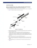
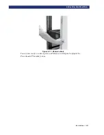
Attaching Cables To SCSI Connectors
If your PowerLoader™ is used on a single-ended SCSI bus, the internal wiring length of
any rack-mounted SCSI system can approach the maximum length specification of a
single-ended SCSI bus. You must locate the rack close to the host computer to avoid
excessive bus length. It is also especially important in single-ended systems to use the
highest quality SCSI cables. Bus errors caused by excessive length or poor quality cables
can significantly degrade performance and reliability.
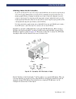
For those dual-drive applications where both AIT drives run in SCSI-SE mode (rather
than LVD mode), each drive must be connected to its own SCSI bus.
Each drive is wired to an independent bus, with a pair of SCSI connectors. Drive 1 shares a
SCSI bus with the PowerLoader™'s robotics. To fully use the bus bandwidth, connect all the
SCSI buses together as shown
. The insets in show how to connect the SCSI cable,
the jumper cables and the terminator for one or two-drive units.
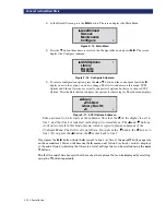
Figure 2–12. Connectors, SCSI Terminator & Cables
Each of the drives in the PowerLoader™ and the robotics is a separate SCSI device. When any
two or more devices are connected to the same SCSI bus, each separate SCSI device must be
assigned a unique SCSI address. For information on assigning SCSI addresses, see the
Configuration section later in this chapter.
SCSI
Terminator
SCSI
Jumper Cable
SCSI
Host Cable
AC Power Cord
DRV 2
Motor
Diagnostic
Expansion Ports
1 DRIVE
2 DRIVES
Terminator
Terminator
SCSI
Host
Cable
SCSI
Host
Cable
SCSI
Jumper
Cable
Summary of Contents for PowerLoaders AIT-2
Page 1: ......
Page 4: ...ii u...
Page 13: ...xi LIST OF FIGURES CONT D...
Page 14: ...xii LIST OF FIGURES CONT D...
Page 16: ...xiv LIST OF TABLES CONT D...
Page 26: ...2 2 u Installation RELEASING THE LOCKDOWN MECHANISM Lockdown Screw...
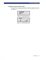
Page 52: ...2 28 u Installation CONFIGURATION OPTIONS DESCRIPTION...
Page 96: ...5 18 u Troubleshooting ERROR RECOVERY...
Page 102: ...A 6 u Specifications SPECIFICATIONS...
Page 104: ...B 2 u...


