


Introduction
t
1-5
SCSI B
US
P
ERFORMANCE
C
ONSIDERATIONS
Features
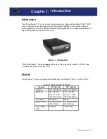
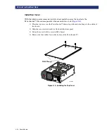
This section describes and illustrates some of the external features of the PowerLoader™ by
Overland Data, Inc, including the control panel, power supply, tape cartridge magazine and
rear ports and connectors.
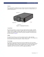
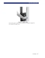
Figure 1–1. PowerLoader™ Front View
Control Panel
The control panel features a 4-line by 20-character backlit liquid crystal display, four LED
indicators and four buttons. The buttons enable the operator to navigate through the menu
structure to select and display operating modes, device status, diagnostic and maintenance
functions, device history and error statistics, and system configuration. The control panel is
described in detail in
Display
The backlit 4-line by 20-character control panel display provides a highly intelligible
presentation of drive and loader status, menu choices and error messages. The scrolling feature
greatly expands the amount of information available to the operator.
Power Supply
The AC Power switch is located on the front panel of the module. The auto ranging power
supply adjusts automatically to either of two operating voltage ranges. The ranges are 100-120
VAC and 200-240 VAC. The power supply is capable of operating at 50 or 60 Hz without any
adjustment or modification. AC power is supplied to the power supply by a single IEC-
compatible socket, which can be connected to any properly grounded outlet.
LP-0009
Summary of Contents for PowerLoaders AIT-2
Page 1: ......
Page 4: ...ii u...
Page 13: ...xi LIST OF FIGURES CONT D...
Page 14: ...xii LIST OF FIGURES CONT D...
Page 16: ...xiv LIST OF TABLES CONT D...
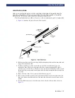
Page 26: ...2 2 u Installation RELEASING THE LOCKDOWN MECHANISM Lockdown Screw...
Page 52: ...2 28 u Installation CONFIGURATION OPTIONS DESCRIPTION...
Page 96: ...5 18 u Troubleshooting ERROR RECOVERY...
Page 102: ...A 6 u Specifications SPECIFICATIONS...
Page 104: ...B 2 u...


