


2-8
u
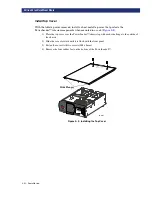
Installation
S
ETTING
U
P
THE
R
ACK
M
OUNT
M
ODEL
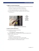
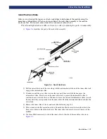
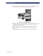
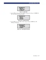
Figure 2–7. Attaching Rack Slides
7) Attach the second inner slide to the other side of the module.
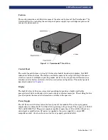
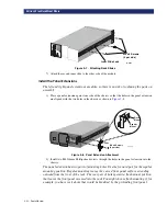
Install the Panel Extensions
The left and right panel extensions are alike, so there is no risk of confusing the parts on
assembly.
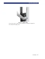
1) Place a panel extension against one side of the chassis so that the holes in the panel extension
are aligned with the two holes in the chassis as shown in
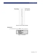
Figure 2–8. Panel Extension Attachment
2) Install two M4 X 8mm Phillips head screws through the holes in the panel extension into the
chassis.
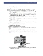
The panel extension has two pairs of mounting holes. Use the forward pair for the regular
mounting position. Regular mounting leaves the curved front panel surface extending
outward from the front of the rack. The rear pair of holes permit a flush mount position
that leaves the front panel recessed into the rack. You might choose flush mounting if, for
example, you have rack doors that would be hindered by the protruding front panel.
M4 x 8 Screws
(3 per side)
Inner Slide Lock
LP-0012
Flush
Mount
Regular
Mount
M4 x 8 Screws
(2 per side)
LP-0016
Summary of Contents for PowerLoaders AIT-2
Page 1: ......
Page 4: ...ii u...
Page 13: ...xi LIST OF FIGURES CONT D...
Page 14: ...xii LIST OF FIGURES CONT D...
Page 16: ...xiv LIST OF TABLES CONT D...
Page 26: ...2 2 u Installation RELEASING THE LOCKDOWN MECHANISM Lockdown Screw...
Page 52: ...2 28 u Installation CONFIGURATION OPTIONS DESCRIPTION...
Page 96: ...5 18 u Troubleshooting ERROR RECOVERY...
Page 102: ...A 6 u Specifications SPECIFICATIONS...
Page 104: ...B 2 u...


