


Installation
t
2-9
S
ETTING
U
P
THE
R
ACK
M
OUNT
M
ODEL
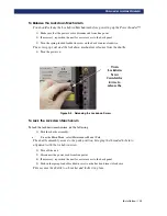
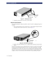
3) Repeat steps 1 and 2 for the other side of the chassis.
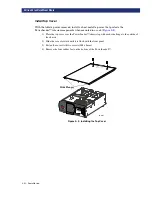
Installing Unit Into a Rack
With the inner rack slides attached to the PowerLoader™ unit and the intermediate/outer
slides separated from the inner slides, you can install the outer rack slides in the rack.
1) Locate the screw holes in the front and rear rails of the cabinet or equipment rack where the
drive is to be installed.
2) Loosely assemble a mounting bracket to each outer slide, using two 10-32 screws and a nut-
plate for each. Select slots in the mounting brackets so the length of the assembly equals the
distance between the front and rear rails of the rack.
3) Fasten each outer slide behind the front rail of the rack using two 10-32 low-profile screws
and one nut plate.
4) Fasten each of the mounting brackets to the front of the rear rail of the rack using two standard
10-32 screws and one nut plate.
5) Tighten the screws installed in step 2.
6) If they are not already locked, pull the intermediate slides toward the front (out of the rack) so
that they lock in the extended position.
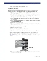
The next step should be performed by two people.
7) Install the Library unit into the rack:
h. In front of the rack, lift the module to its installed height.
i. Engage the inner slides mounted on the module with the intermediate slides protruding from the
rack
j. Slide the module toward the rack until the inner slide's lock engages the intermediate slides.
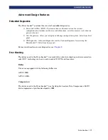
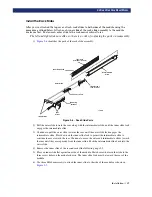
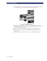
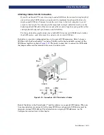
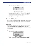
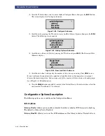
k. Depress the lock tab and continue until the lock tab engages in the locking hole shown in
. This leaves the entire module protruding from the rack, locked in position, supported
by slides.
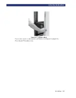
Figure 2–9. Locking Tab
12) Press inward (toward the module) on each of the inner slide locks to permit the intermediate
slides to move toward the rack.
Locking Tab
Summary of Contents for PowerLoaders AIT-2
Page 1: ......
Page 4: ...ii u...
Page 13: ...xi LIST OF FIGURES CONT D...
Page 14: ...xii LIST OF FIGURES CONT D...
Page 16: ...xiv LIST OF TABLES CONT D...
Page 26: ...2 2 u Installation RELEASING THE LOCKDOWN MECHANISM Lockdown Screw...
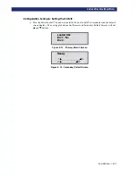
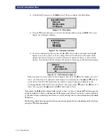
Page 52: ...2 28 u Installation CONFIGURATION OPTIONS DESCRIPTION...
Page 96: ...5 18 u Troubleshooting ERROR RECOVERY...
Page 102: ...A 6 u Specifications SPECIFICATIONS...
Page 104: ...B 2 u...


