- 18 -
- 19 -
ORION
Hybrid Video System
BLU1
BLU2
PWR
VIDEO
COMM
ID
RECEIVER
MODULE
PWR 1
PWR 2
PWR 3
PWR 4
PWR IP
P-CON
POWER
AC INPUT
OFF ON
PWR
LAN
P-CON
232IN
232OUT
COMM4 VIDEO4
COMM3 VIDEO3
COMM2 VIDEO2
COMM1 VIDEO1
DVI IN4
DVI IN3
DVI IN2
DVI IN1
LOOP IN
LOOP OUT
01
2 345
678
9
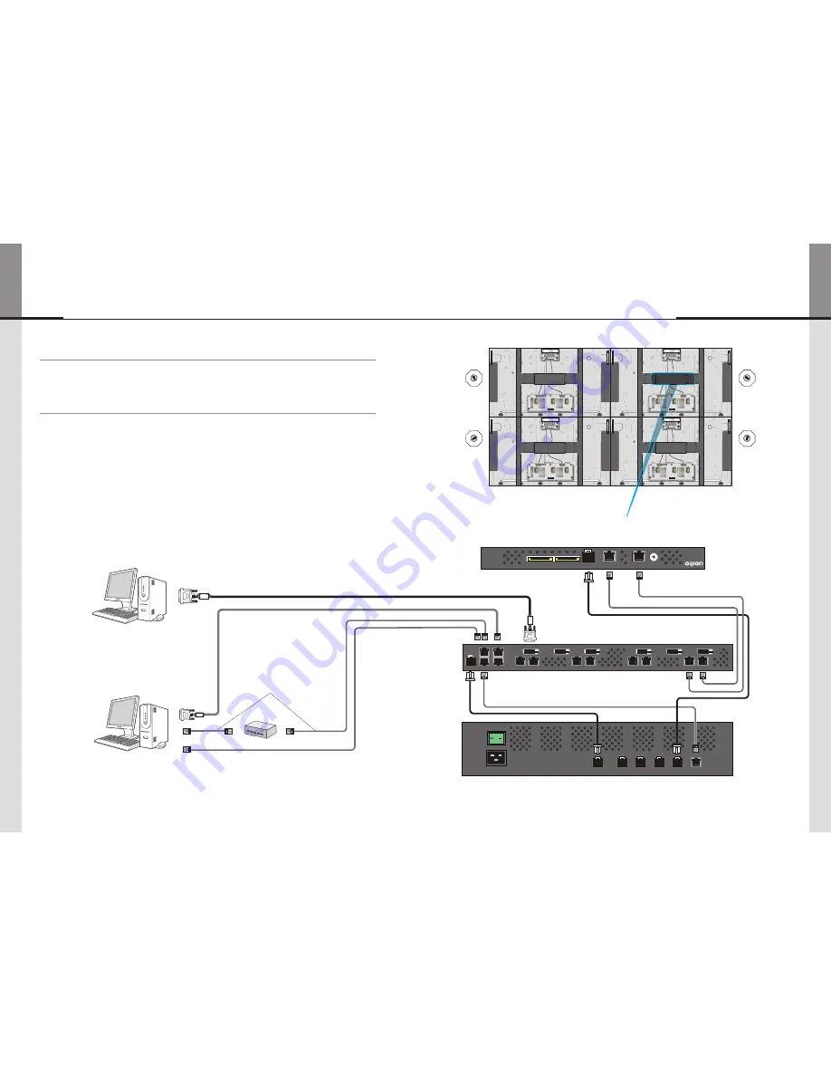
4. How to Connect Cables
• Do not connect/disconnect cables while MLCD or other external equipments are turned on.
• First turn off the power all the attached equipment and make connections.
4.1. Single Image Processor Connection (for One 2X2 MLCD formation)
• Connect the RS-232C IN port of the Image Processor to the Com port of the PC with RS-232C
cable.
• Use MSCS (Multi-Screen Control System) program to turn on or off the display and control the
screen.
• To control the display, the ID on the Image Processor and the ID in the MSCS must be identical.
• In case there is no Com port, it is necessary to use the converting gender from USB to
RS-232C. There can be some malfunctions based on the gender makers.
• The IDs for each Receiver Module must not be overlapped. It should be set from 1 to 4.
• The ID for Image Processor must be set as 1.
• The IDs for Image Processor and Receiver should be set after turning off the power.
PC
Receiver Module (Lower Deck)
Image Processor Module (Rear)
Power Module (Rear)
PC (MSCS) to control MLCD
RS-232C (Maximum 15m)
DVI connection
(Maximum 5m)
※
If you need longer connection, please use
DVI boosters or DVI fiber-optic cable.
※
Select only one cable
connection for the control signal
between RS-232C cable and
LAN cable.
※
Make sure there is at least 4.4cm (1U) clearance between Image Processor Module and Power Module.
HUB or Router (Wireless & Cable)
LAN Cable
(Direct Cable)
LAN Cable
(Cross Cable)
0
1 2
3 4
5
678
9
ID : 1
0
1 2
3 4
5
678
9
ID : 2
0
1 2
3 4
5
678
9
ID : 3
0
1 2
3 4
5
678
9
ID : 4
Summary of Contents for OLW-4651
Page 42: ... 80 ORION MEMO ...


