background image

- 48 -

- 49 -

ORION 

Hybrid Video System

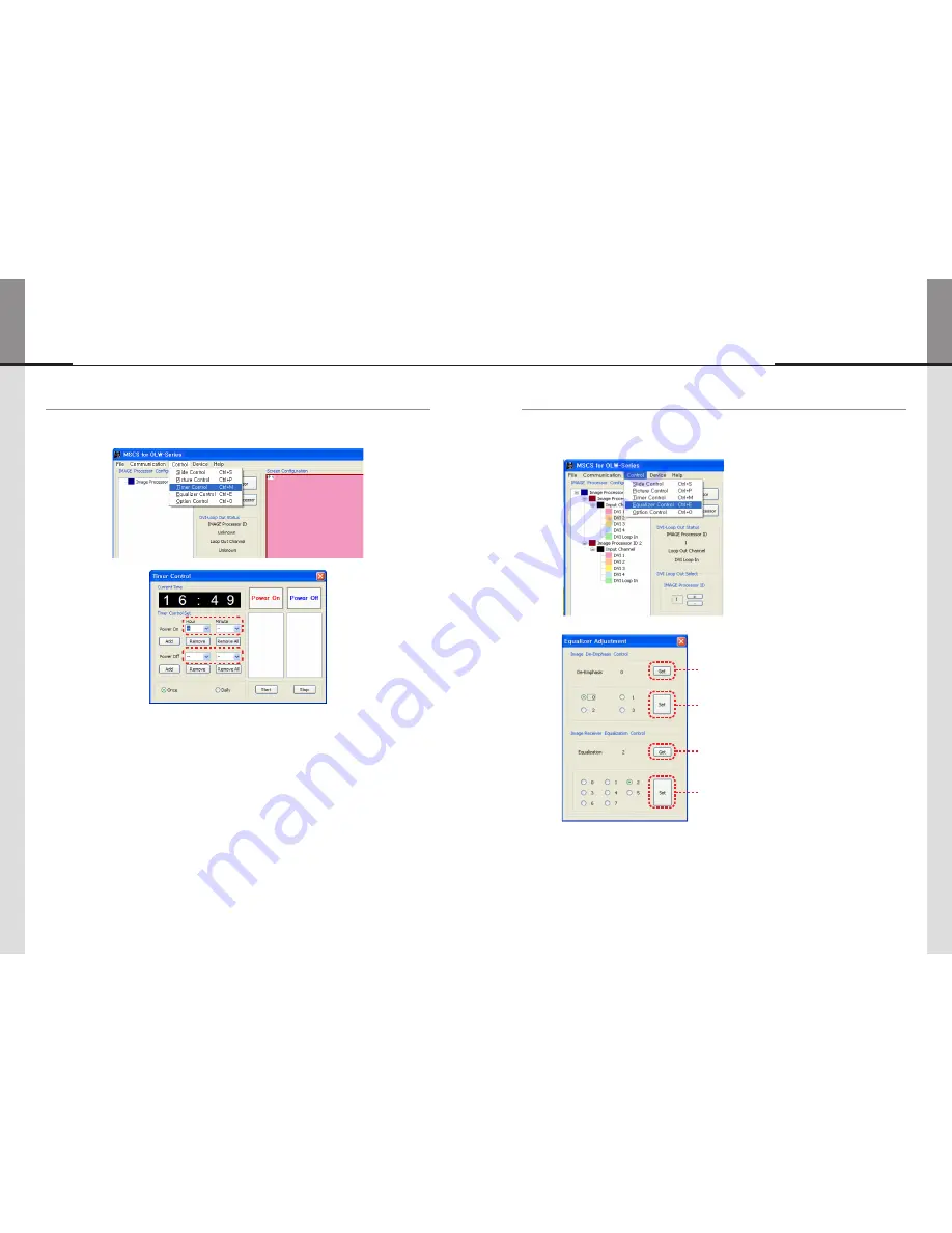
5.13. Timer Control

• Users can set the time for turn on or turn off.  
• To use this function, click Menu -> Control-> Timer Control or use 

'Ctrl +M'

 keys from the keyboard.

Timer Control Dialog

• How to set the time of 

power on or off

.

a.  Select Hour and Minutes of turn on or off
b.  After setting Power On/Off time, click 

“Add” button

 to add it to Power On/Off List Box. 

You can save up to 10 settings for Power On/Off. Also, you can delete the saved settings in the List 
Box one by one with 

“Remove” button

. If you delete all the settings, click 

“Remove All” button

.

c.  Select 

once

 for one time use and Daily for daily use, then click 

'Start'

d. 

Power on or off

 signal will be transmitted to MLCD at the time of user set. 

• 

Time Dialog

 must be activated to use Timer function.

5.14. Equalizer Control

• You can control the Equalizer for more stable image quality according to the length of the image signal 

cable.

• Click Menu -> Control-> Equalizer Control or press

 "Ctrl + E"

 to use Equalizer Control Dialog

• Read the configuration of DVI Loop Out.

• Configure De-Emphasis.

• Read Equalization value.

• Configure the Equalizer

Summary of Contents for OLW-4651

Page 1: ...his user s manual for safety before installing this product This product is manufactured for Multi LCD model only User s Manual OLW 4651 OLW 5550 OLWU 5520 OLWU 5550 Address 217 1gongdan ro Gumi si Gyeongsangbuk do Korea Tel 82 2 6678 8533 Fax 82 2 6678 8599 A revolutionary MLCD A revolutionary MLCD Hybrid Video System ...

Page 2: ...a device designed for business purpose with a safety certificate for electromagnetic interference which user should be mindful of Important Safety Instructions 1 Read these instructions 2 Keep these instructions 3 Heed all warnings 4 Follow all instructions 5 Do not use this apparatus near water 6 Clean only with dry cloth 7 Do not block any ventilation openings Install in accordance with the manu...

Page 3: ... be pulled out from the mains socket therefore the mains plug shall be readily operable 2 WARNING To Reduce The Risk Of Fire Or Electric Shock Do Not Expose This Appliance To Rain Or Moisture 3 Apparatus shall not be exposed to dripping or splashing and no objects filled with liquids such as vases shall be placed on the apparatus 4 Use only a properly grounded plug and receptacle 5 Warning CAUTION...

Page 4: ...etween 0 35 C For ground of MLCD and application devices it should be connected as frame ground Considering MLCD Max power consumption check the main electric specification Consideration for easier service When you design the exterior design for MLCD system consider easier disassembly for possible service occasion in the future The sliding Universal Unit of ORION is recommended for easier service ...

Page 5: ...ck and lean over the LCD to avoid panel touches ground or floor Please do not lean over the LCD It may damage the bottom part of the LCD If you need to lay down LCD as face down position please use shock absorbing pads under the LCD Please do not lean over the LCD toward the edge part It may damage the edge part of the LCD If you need to lay down LCD as face up position please be cautious for fall...

Page 6: ... display Suitable operating time under 20 hours a day Periodical display contents change from static image to moving picture Periodical background color and character image color change DEPARTURE Å Æ DEPARTURE Flight No Time Gate Flight No Time Gate UA 012 11 20 A02 UA 012 11 20 A02 KE 732 12 10 K17 KE 732 12 10 K17 AN 291 12 45 F11 AN 291 12 45 F11 Change the images of little luminance difference...

Page 7: ...ny object If the ventilation hole is blocked the inside temperature may rise to cause overheating resulting in fire Do not poke the front screen with sharp material It may damage the screen and may cause malfunction of the product Do not lean against the product or keep it leaned It may cause injury or failure Do not put it at any place with much humidity dust oil smoke or steam It may cause failu...

Page 8: ...ansferring LVDS signal to LCD Panel Lower Deck BLU1 BLU2 PWR VIDEO COMM ID RECEIVER MODULE 0 1 2 3 4 5 6 7 8 9 BLU1 BLU2 Power supply and control signal input ports for the back light unit in LCD panel VIDEO Image signal input port COMM Control signal input port ID ID configuration switch for Receiver Module Front Rear Receiver Module ...

Page 9: ... ports LOOP IN DVI signal input port for multi Image Processors LOOP OUT DVI signal output port for multi Image Processors COMM1 COMM4 Receiver Module control signal output port VIDEO1 VIDEO4 Receiver Module image signal output port 2 4 Image Processor Module Front PWR 1 PWR 2 PWR 3 PWR 4 PWR IP PWR S FAN1 AC FAN2 POWER MODULE PWR 1 PWR 4 Indicator LEDs of the power output port for the Receiver Mo...

Page 10: ...ion or shock LCD set may fall and damaged Next or near to Sprinkler sensors The sensors may detect heat from a set and sprinkler can be activated Around high voltage power lines Noise from the power line may affect screen images Around heating apparatus LCD set may be overheated and damaged MAIN FRAME Wall Mounting Unit Option The set can be installed on the wall as shown below For further informa...

Page 11: ...the ID in the MSCS must be identical In case there is no Com port it is necessary to use the converting gender from USB to RS 232C There can be some malfunctions based on the gender makers The IDs for each Receiver Module must not be overlapped It should be set from 1 to 4 The ID for Image Processor must be set as 1 The IDs for Image Processor and Receiver should be set after turning off the power...

Page 12: ...WER AC INPUT OFF ON PWR LAN P CON 232IN 232OUT COMM4 VIDEO4 COMM3 VIDEO3 COMM2 VIDEO2 COMM1 VIDEO1 DVI IN4 DVI IN3 DVI IN2 DVI IN1 LOOP IN LOOP OUT 0 1 2 3 4 5 6 7 8 9 BLU1 BLU2 PWR VIDEO COMM ID RECEIVER MODULE PWR 1 PWR 2 PWR 3 PWR 4 PWR IP P CON POWER AC INPUT OFF ON PWR LAN P CON 232IN 232OUT COMM4 VIDEO4 COMM3 VIDEO3 COMM2 VIDEO2 COMM1 VIDEO1 DVI IN4 DVI IN3 DVI IN2 DVI IN1 LOOP IN LOOP OUT 0...

Page 13: ...t without prior notice 5 2 Start MSCS MSCS is an application program needed to control MLCD When you execute MSCS v X X for your product at the installation screen it will create a new folder at C Program File MSCS vX X and an icon on your computer screen By double clicking the MSCS v X X icon the initial screen image of MSCS v X X will be displayed as shown in the picture Main Image of MSCS Multi...

Page 14: ...atically recognized and displayed Com Port Configuration Baud Rate 115200bps Fixed Data Bit 8Bits Parity None Stop Bit 1Bit Flow Control None 5 3 2 Setting of LAN Port 1 In case of connecting to a LAN Hub This function is used to control the MLCD via LAN PORT During the setting process MLCD and control PC should be connected via RS 232C cable only Do not connect ethernet cable After setting proces...

Page 15: ... the IP address is saved correctly 7 Close the LAN Configurator 2 In case of connecting directly to user s computer Cross LAN cable is required to connect Check the network informations 1 Execute the LAN Configurator from installation CD 2 Select Com Port and select OPEN 3 Select ID of MLCD which you want to control ...

Page 16: ...dio button 4 Type in IP Address of MLCD 5 Click Ping Test to check status of communication 6 Close the Commnication setup window Menu Description Serial Set the serial communication as a default communication Com Port Set the port of a PC to communicate with MLCD Baud Rate Fixed at 115200bps Caution Users cannot change the Baud rate Socket Set the Ethernet LAN communication Edit Box Set the IP add...

Page 17: ... connection is successfully completed after setting Com Port following Message dialog is displayed The dialog window will be disappeared in 1 second When the connection is successfully completed after setting Lan Port following Message dialog is displayed The dialog window will be disappeared in 1 second 5 5 Selecting the command transmission method ONE LCD Transmit Protocol Command to one MLCD AL...

Page 18: ... in the Tree View window 5 7 Multi Screen Configuration 1 Screen Configuration Dialog will pop up when you Click Image Processor ID Node in the Tree View window 2 Screen formations can be selected by Screen Configuration Dialog 3 The number of LCD set in the horizontal direction and vertical direction can be increased or decreased to make your selected screen formation In case of 1X4 formation the...

Page 19: ...and input channel will be displayed 8 As you click Add Image Processor button again after one Image Processor Module is added additional Image Processor Module is created as shown in the picture below 9 Select 2x2 LCD set formation in Screen Configuration Dialog and click button to increase the number 1 to 2 and click button 4x2 LCD screen formation will be created at Screen Configuration ...

Page 20: ...itialize Tree View window with Remove All IMAGE Processor button Unexpected momentary power cut may cause malfunction If you have the malfunction from power cut unplug the power cord and plug it again at least 1 minute later Caution 5 9 Power On Off 1 Select Broadcast or ALL LCD for command transmission method and click POWER ON All connected devices will be turned on ...

Page 21: ...all screens by clicking Play button Image Processor ID and the Input Channel will be displayed on the screen of MSCS 5 8 2 Mouse left button use e g select DVI 3 1 Select the input channel source of your choice at the Input Channel in Tree View window 2 The selected input source will be displayed at the all screens by clicking the left button of the mouse Image Processor ID and the Input Channel w...

Page 22: ...Selecting Loop Out Channel DVI 3 for Image Processor Module ID 1 Read the configuration of De Emphasis Read Æ Æ Æ 1 Select the ID number of Image Processor Module to make Loop Out Channel Click button and button to increase or decrease the number The numbers for Image Processor ID are available from 1 to 9 2 Select the DVI channel you want and Click Set button DVI1 2 3 4 Loop In Channel 3 The info...

Page 23: ...n time 10 seconds 1 hour Operation Time can be set from 10 seconds up to 1 hour Save the screen format by clicking Add button Slide Show Status Window Display the Slide Show Configuration Operation Time Set the duration time for each screen format of the Slide Show Configuration Add or delete the screen format for the Slide Show Play Repeat Repeat the Slide Show Start Start the Slide Show Stop Sto...

Page 24: ... the same manner 4 Click Start button after screen configuration Screen formats are displayed according to the configured time and sequence The screen formats of Slide Show are displayed only for scheduled time 5 To repeat the configured screen format click Repeat button ...

Page 25: ... in Edit Box and press Enter key Or click button using mouse Click Exit button or press Ctrl X using keyboard to close Picture Control window Color Temp Change the color temperature of the screen Normal Initial setting Proper for normal video image view Studio Low Color temperature Proper for broadcasting purpose Brightness The range of Brightness you can adjust is 0 to 100 Contrast The range of C...

Page 26: ... the saved settings in the List Box one by one with Remove button If you delete all the settings click Remove All button c Select once for one time use and Daily for daily use then click Start d Power on or off signal will be transmitted to MLCD at the time of user set Time Dialog must be activated to use Timer function 5 14 Equalizer Control You can control the Equalizer for more stable image qua...

Page 27: ...a Rate 0 10 m Over 10m 1080P 1 65Gbps 0 1 2 5 5 15 Option Control There are various optional functions for convenient use Click Menu Control Option Control or press Ctrl M keys to use Option Control Dialog Test Pattern Display the embedded patterns on the screen Pattern 4 Patterns are embedded Red Green Blue White Test Screen Return to the input source Global Offset The images on the seam area bet...

Page 28: ...ll be 0x11 0x12 0x13 and 0x14 Check Sum Add values from STX to Data and execute logical operation NOT B Broadcast Command STX CMD LENGTH Data Check sum ETX ID 1Byte Image Processor Module ID IP ID Value 0X02 0X40 0X01 0x00 Variable 0x03 Send To MLCD Send the same command for all MLCD No response will be made Receive Data STX CMD LENGTH Data Check sum ETX ID 1Byte Image Processor Module ID IP ID Va...

Page 29: ...D of IP Board 1 4 In case of 4 LCD sets IDs will be 0x11 0x12 0x13 and 0x14 Check Sum Add values from STX to Data and execute logical operation NOT Send To MLCD CMD 0x41 ID Range 0x11 0x94 Upper Byte is Image Processor Module Set ID 1 9 and Lower Byte is the ID of IP Board 1 4 In case of 4 LCD sets IDs will be 0x11 0x12 0x13 and 0x14 Check Sum Add values from STX to Data and execute logical operat...

Page 30: ... 0x11 0x94 Upper Byte is Image Processor Module Set ID 1 9 and Lower Byte is the ID of IP Board 1 4 In case of 4 LCD sets IDs will be 0x11 0x12 0x13 and 0x14 Check Sum Add values from STX to Data and execute logical operation NOT Receive Data STX CMD LENGTH Data Check sum ETX ID 1Byte Master Image Processor Module ID IP ID Value 0X02 Variable 0X02 Variable Variable 0x01 Variable 0x03 5 Graphic Use...

Page 31: ...and execute logical operation NOT ID Range 0x11 0x94 Upper Byte is Image Processor Module Set ID 1 9 and Lower Byte is the ID of IP Board 1 4 In case of 4 LCD sets IDs will be 0x11 0x12 0x13 and 0x14 Check Sum Add values from STX to Data and execute logical operation NOT 8 Firmware Default Flash Screen Data Load Initialize the firmware as the phase before adjusting any values at the factory STX CM...

Page 32: ...Value 0X02 Variable 0X01 0x00 Variable 0x03 Send To MLCD Send the same command for all MLCD No response will be made 11 Dimming Control The command for controlling the backlight of LCD A General Command STX CMD LENGTH Data Check sum ETX ID 1Byte Control Image Processor Module ID IP ID Value 0X02 0xDC 0X02 Variable Variable Variable Variable 0x03 Send To MLCD CMD 0xDC Control Value 0 100 0x00 0x64 ...

Page 33: ... is the ID of IP Board 1 4 In case of 4 LCD sets IDs will be 0x11 0x12 0x13 and 0x14 Check Sum Add values from STX to Data and execute logical operation NOT Commands cannot be executed with Broadcast mode Receive Data STX CMD LENGTH Data Check sum ETX ID 1Byte Master Image Processor Module ID IP ID Value 0X02 Variable 0X02 Variable Variable 0x01 Variable 0x03 ID Range 0x11 0x94 Upper Byte is Image...

Page 34: ...2 0x87 0X02 Variable Variable 0x01 Variable 0x03 Send To MLCD CMD 0x87 Receive Data STX CMD LENGTH Data Check sum ETX ID 1Byte Control Image Processor Module ID IP ID Value 0X02 Variable 0x02 Variable Variable Variable 0x03 Control Value 0 0x00 100 0x64 ID Range 0x11 0x94 Upper Byte is Image Processor Module Set ID 1 9 and Lower Byte is the ID of IP Board 1 4 In case of 4 LCD sets IDs will be 0x11...

Page 35: ...r Board 1 Status 1 byte 0 PowerOff Stand by 1 PowerOn Working 2 Power Board 2 Status 1 byte 0 PowerOff Stand by 1 PowerOn Working 3 Power Board 3 Status 1 byte 0 PowerOff Stand by 1 PowerOn Working 4 Power Board 4 Status 1 byte 0 PowerOff Stand by 1 PowerOn Working 5 Redundant Power Status 1 byte It is all time Power Off It will be turned on if there is any abnormal situation for Power 1 2 3 and 4...

Page 36: ...Month 2bytes Day 2bytes Version Mode Release or Test 1byte Ex Power Board December 29th 2012 Release PWR ASCII 0x50 0x57 0x52 0x01 0x02 0x01 0x02 0x02 0x09 R ASCII 0x52 ID Range 0x19 0x99 Upper Byte is Image Processor Module Set ID 1 9 and Lower Byte is the ID of Power Board fixed as 9 In case of 4 LCD sets current status information of 4 sets can be obtained by sending command with the ID of 0x19...

Page 37: ...ble 0x00 Variable 0x03 Equalizer Control Value 0 0x00 1 0x01 2 0x02 3 0x03 4 0x04 5 0x05 6 0x06 7 0x07 ID Range 0x15 0x98 Upper Byte is Image Processor Module Set ID 1 9 and Lower Byte is the ID of IR Board 5 8 In case of 4 LCD sets IDs will be 0x15 0x16 0x17 and 0x18 Check Sum Add values from STX to Data and execute logical operation NOT 21 DE Emphasis Get Current Status The command for collectin...

Page 38: ...0x11 0x12 0x13 and 0x14 Check Sum Add values from STX to Data and execute logical operation NOT 23 Equalizer Get Current Status The command for collecting information of the current Equalizer configuration Equalizer is adjusted to compensate the input signal loss according to the cable length CMD 0x52 A General Command STX CMD LENGTH Data Check sum ETX ID 1Byte Image Processor Module ID IR ID Valu...

Page 39: ...ta and execute logical operation NOT STX ETX 02 03 Attachment ASCII to HEX Conversion Table 7 Before calling for service Before calling for any repair check the following and then refer to a near A S center Tick sound from the main body If there is no problem with the screen or sound the tick sound is likely to result from the cabinet lightly shrinking with the change of room temperature The sound...

Page 40: ...74 250 1980 1280 80 220 750 720 5 20 HDTV 750p60 60 45 000 74 250 1650 1280 80 220 750 720 5 20 HDTV 1080i50 50 28 125 74 250 2640 1920 88 148 1125 1080 10 30 HDTV 1080i60 60 33 750 74 250 2200 1920 88 148 1120 1080 10 25 HDTV 1080p50 50 56 250 148 500 2640 1920 88 148 1125 1080 5 36 HDTV 1080p60 60 67 500 148 500 2200 1920 88 148 1125 1080 5 36 HDTV 9 Specification MODEL NAME OLW 4651 OLW 5550 OL...

Page 41: ...N1 AC FAN2 88mm 0 2 460mm 0 2 88mm 0 2 PWR 1 PWR 2 PWR 3 PWR 4 PWR IP PWR S FAN1 AC FAN2 POWER MODULE PWR 1 PWR 2 PWR 3 PWR 4 PWR IP P CON POWER AC INPUT OFF ON 443 4mm 0 2 460mm 0 2 44mm 0 2 44mm 0 2 OUTPUT 1 OUTPUT 2 ID OUTPUT 3 OUTPUT 4 IMAGE PROCESSOR MODULE IN DVI 1 NO SIGNAL IN DVI 1 NO SIGNAL IN DVI 1 NO SIGNAL IN DVI 1 NO SIGNAL 01 2 3 4 5 6 7 8 9 PWR LAN P CON 232IN 232OUT COMM4 VIDEO4 CO...

Page 42: ... 80 ORION MEMO ...

Reviews: