background image

7    Teaching pendant operation


56


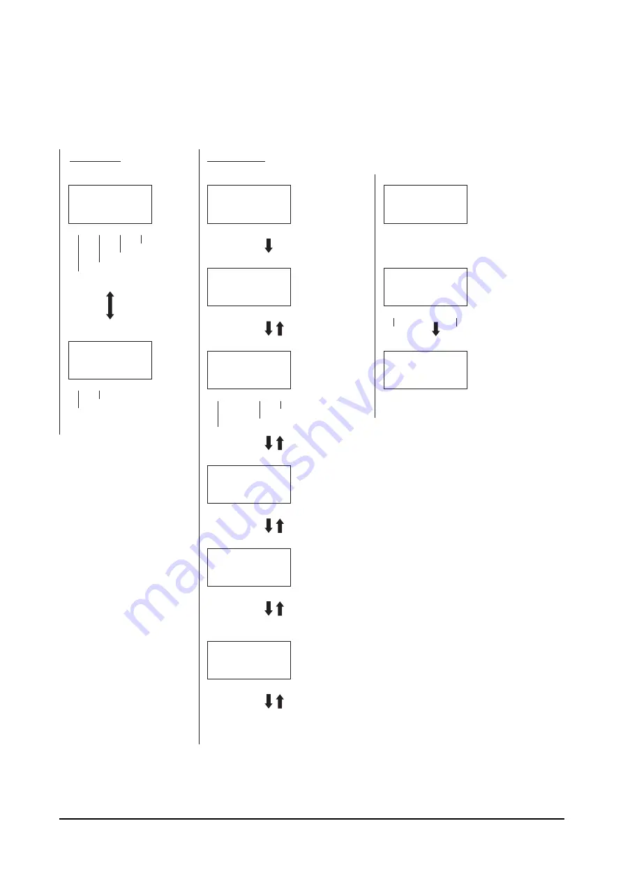
PRG mode 

C


2 4 )  & C V C      + &   
      0 Q  F C V C
         ' 0 6  ' F K V
/ Q F G  % N T  + P U  & G N

2 4 )  & C V C      + &   
      0 Q  F C V C
         ' 0 6  ' F K V
/ Q F G  % N T  + P U  & G N

2 4 )      1 2  6 [ R G
# D U  + P E  + P E
      φ  ψ  ' 0 6  5 G V
/ Q F G            

2 4 )      2 Q U   + P E
2 Q U           O O
     M G [ U  ' 0 6  5 G V
/ Q F G      4 O V  & E V

2 4 )      5 R G G F
5 R F          O O  U
     M G [ U  ' 0 6  5 G V
/ Q F G            

2 4 )      2 W U J  % W T 
2 W U J  % W T     
     M G [ U  ' 0 6  5 G V
/ Q F G            

2 4 )      1 2  ( W P E
( W P E  5 K P I N G / Q V K Q P
      φ  ψ  ' 0 6  5 G V
/ Q F G            

2 4 )  & C V C      + &   
0 Q     0 Q  F C V C

/ Q F G  # E N T        

2 4 )      4 O V   + P E
2 Q U           O O
      φ  ψ  ' 0 6  5 G V
/ Q F G            

2 4 )      & E V
/ Q V Q T  H T G G
1 - !  0 Q     ' 0 6  5 G V
/ Q F G      ; G U  0 Q

2 4 )      & E V   + P E
2 Q U           O O
/ Q V Q T ( T G G  ' 0 6  5 G V
/ Q F G            

[

]

[

]

[

]

[

]

[

]

[

]

[

]

[

]

[ENT]

[

]

[

]

Select using [

][

].

Select a data No. using 
the numerical keys or 
[

][

][

][

].

Select using [

][

].

Enter using the 
numerical keys.

Enter using the 
numerical keys.

Enter using the 
numerical keys.

If "SingleMotion" or "LinkedMotion" has been selected as 
the operation mode, the display returns to the No. selection.

No. selection 1

No. selection

Operation method

No. selection 2

Position (numerical value entry)

Operating speed

Push current
(Displayed if the operation function is "PushMotion")

Operating function

First screen

Data creation

Move using [

][

].

Move manually.

Remote teaching

Direct teaching

To No. selection

To data deletion

To data insertion

To data clear

To PAR mode

To PAR mode

To clearing all operation data

[F1] 
to PAR mode

[F1] 
to PAR mode

[F1] 
to PAR mode

[F1] 
to PAR mode

[F1] 
to PAR mode

To PAR mode

To remote teaching

[SHIFT]

To direct teaching

[ESC] to first screen of EXT mode

[ESC] to first screen

[F1] 
to PAR mode

[F1] 
to PAR mode

To PAR mode

To position (numerical value entry)

[F1]

[F4]

[F3]

[F1]

[F3]

[F4]

[F1]

[F2]

[F3]

[F4]

[F1]

[F2]

Summary of Contents for EZ limo ESMC-A

Page 1: ...OPERATING MANUAL Thank you for purchasing an Oriental Motor product This Operating Manual describes product handling procedures and safety precautions Please read it thoroughly to ensure safe operati...

Page 2: ...operation 28 4 6 Operation by pulse input 29 4 7 A phase pulse output B phase pulse output 29 4 8 Timing output 30 4 9 Area output 30 4 10 Stopping function 30 4 11 Stopping the motor excitation 31 4...

Page 3: ...er mode driver mode Controller mode The motorized actuator is operated in accordance with the operation data stored in the controller Driver mode The motorized actuator is operated by means of externa...

Page 4: ...to 40 C 32 to 104 F non freezing 25 to 70 C 77 to 158 F non freezing Ambient humidity 85 or less non condensing Altitude Up to 1000 m 3300 ft above sea level Up to 3000 m 10000 ft above sea level Surr...

Page 5: ...ESMC C EMI Emission Tests Radiated Emission Test Conducted Emission Test EN 61000 6 4 EN 55011 EN 61000 6 4 EN 55011 EN 55011 EMS Immunity Tests Electrostatic Discharge Immunity Test Radiation Field I...

Page 6: ...onnector is used to connect the Emergency stop circuit Motor connector This connector is used to connect the motor cable of the motorized actuator CHARGE LED This LED will be lit when the main power s...

Page 7: ...rnal settings cannot be changed Resolution maximum operating speed maximum acceleration deceleration motor control settings Note Be sure to confirm that the motorized actuator model shown on the contr...

Page 8: ...9 in or more Side 20 mm 0 79 in or more Side 20 mm 0 79 in or more 25 mm 0 98 in ESMC A ESMC C 180 mm 7 09 in ESMC K 165 mm 6 50 in Front 80 mm 3 15 in or more to allow cable connection 2 2 How to ins...

Page 9: ...BQZ 4 PHOENIX CONTACT GmbH Co KG PT2 PE S120AC ST PT2 PE S230AC ST Note When measuring dielectric strength of the equipment be sure to remove the surge arrester or the surge arrester may be damaged Wi...

Page 10: ...or cable Shielded cable Pendant cable Host controller To sensor Grounded panel Ground cable Motor cable Shielded cable Mains filter DC power supply DC power supply A A 3 Shielded cable Battery 1 A Cab...

Page 11: ...MC K DC power supply Motorized actuator Emergency stop circuit Controller key Teaching pendant EZT1 Or Motor cable Data editing software EZED2 The software comes with a PC interface cable 1 Absolute m...

Page 12: ...The maximum current varies depending on the motorized actuator connected to the controller EZSM3 EZSM4 SPRM6 2 1 A EZSM6 SPFM6 SPFM8 SPVM6 SPRM8 3 0 A SPVM8 PWAM8 3 5 A PWAM6 3 9 A 24 VDC ESMC K ESMC...

Page 13: ...I O 2 Assembling the connector M2 Tightening torque 0 3 to 0 35 N m 42 6 to 49 7 oz in M2 5 Tightening torque 0 5 to 0 55 N m 71 0 to 78 1 oz in Pin assignments of sensor I O connector Pin No Signal...

Page 14: ...18 IN COM1 3 4 Power supply input for input signals 19 I O GND Power supply GND for I O 30 REQ ABS data request 4 12 Reading current position data on p 31 31 FWD FP 32 FWD FP 33 P24 FWD P24 FP FWD FW...

Page 15: ...a or stopped inside the area OUT0 Used to read the current position TIM Output when the excitation sequence is at step 0 AREA 4 9 Area output on p 29 OUT0 TIM on p 6 T UP OUT1 2 T UP Output when a pus...

Page 16: ...less R0 10 mA or less R1 15 mA or less R1 15 mA or less 18 11 M5 16 START IN COM1 7 ACL CK 8 FREE 9 STOP 10 HOME PRESET 17 REQ 30 P24 FWD 33 FWD 32 P24 RVS 36 RVS 35 ALM 2 MOVE 3 END OUTR 4 AREA OUT0...

Page 17: ...0 10 mA or less R1 15 mA or less R1 15 mA or less 18 ACL CK IN COM1 IN COM2 8 FREE 9 C OFF 10 HOME PRESET 17 REQ 30 P24 FP 33 FP 32 P24 RP 36 RP 35 ALM 2 MOVE 3 END OUTR 4 TIM OUT0 5 T UP OUT1 OUT COM...

Page 18: ...r less R0 10 mA or less R1 15 mA or less R1 15 mA or less 11 M5 16 START 7 ACL CK 8 FREE 9 STOP 10 HOME PRESET 17 REQ 30 P24 FWD 33 FWD 32 P24 RVS 36 18 1 RVS IN COM1 IN COM2 OUT COM 35 ALM 2 MOVE 3 E...

Page 19: ...mA or less R1 15 mA or less R1 15 mA or less ACL CK 8 FREE 9 C OFF 10 HOME PRESET 17 REQ 30 P24 FP 33 FP 32 P24 RP 36 18 RP IN COM1 OUT COM 35 ALM 2 1 MOVE 3 END OUTR 4 TIM OUT0 5 T UP OUT1 6 ASG1 20...

Page 20: ...and emergency stop system EN 954 1 Category 1 EN 60204 1 Stop category 0 Teaching pendant Controller PENDANT PENDANT switch SB3 SB2 SB1 KA1 FU1 FU2 6 5 EMG L N 0 V 0 V 24 VDC 24 VDC KA1 and SB2 must u...

Page 21: ...the controller before removing the battery from the controller Pin assignments of battery connector Battery power input Battery power ground Note The product is shipped with an uncharged battery Alwa...

Page 22: ...e motor Starting position of return to home operation Starting direction of return to home operation Opposite the motor side Starting direction of return to home operation Motor side Broken line indic...

Page 23: ...mode The HOMELS becomes the home Trapezoid operation is performed at the starting speed of return HOMELS LS LS HOMELS LS LS HOMELS LS LS HOMELS LS LS HOMELS LS LS HOMELS LS LS HOMELS LS LS HOMELS LS L...

Page 24: ...ng data Operation data Positioning mode travel direction operating speed operation function Operation data are set individually in operation data No 1 to 63 Speed data Starting speed acceleration dece...

Page 25: ...ted No 1 No 2 No 3 No 4 Operating speed 30 mm s 1 18 in s Starting speed 6 mm s 0 24 in s When No 4 is executed No 4 10 mm 0 39 in 0 mm 0 in 60 mm 2 36 in 100 mm 3 94 in 120 mm 4 72 in When the last o...

Page 26: ...RT input Execution example 1 No 1 No 1 No 2 No 3 M0 to M5 input Select No 0 Select No 11 START input START input 1st Execution example 2 No 11 No 1 No 12 START input 2nd START input 3rd START input 1s...

Page 27: ...ng current conforms to the value set as the push motion current Note Do not operate the slider in the push motion mode If push motion operation is performed at a speed greater than 6 mm s 0 24 in s an...

Page 28: ...7 in s 6 mm s 0 24 in s 0 45 m s2 1 476 ft s2 0 45 m s2 1 476 ft s2 60 mm s 2 36 in s 3 10 mm s 0 39 in s 4 Not set M0 to M5 input No 1 No 2 No 3 No 2 No 0 FWD input RVS input M0 to M5 input FWD input...

Page 29: ...er unit and other functions of the controller Note The pulse output delays behind motorized actuator movement by up to 1 ms The output may be used to verify the stop position of the motorized actuator...

Page 30: ...the area set by the area 1 and area 2 parameters coordinate direction coordinate direction coordinate direction coordinate direction coordinate direction coordinate direction Area 1 Area 2 Area 1 Area...

Page 31: ...al Status 000 0 0 0 0 0 bit 0 Overflow bit 1 Overspeed bit 2 Absolute data lost bit 3 Low voltage warning bit 4 No battery bit 5 to 7 Not defined always 0 Alarm 68 hexadecimal Checksum About checksum...

Page 32: ...pending on the load and operating speed 5 1 Return to home operation C D 6 ms or less 10 ms or less MOVE output ON or elapse of at least 4 ms HOMELS HOME input MOVE output END output coordinate direct...

Page 33: ...FF OFF ON ON ON OFF 46 ON OFF ON ON ON OFF 15 OFF OFF ON ON ON ON 47 ON OFF ON ON ON ON 16 OFF ON OFF OFF OFF OFF 48 ON ON OFF OFF OFF OFF 17 OFF ON OFF OFF OFF ON 49 ON ON OFF OFF OFF ON 18 OFF ON OF...

Page 34: ...irection ON OFF ON OFF ON OFF MOVE output 2 ms or less 2 ms or less ON OFF 1 pulse input mode FP input RP input END output 3 ms or less 3 ms or less cordinate direction cordinate direction MOVE output...

Page 35: ...ms or more ON OFF ON OFF ON OFF ON OFF MOVE output OFF or elapse of at least 4 ms Motor excitation Immediate stop Electromagnetic brake actuation STOP input START input MOVE output END output Stop Rel...

Page 36: ...ending on the load and operating speed the section indicated by in the timing chart 5 6 Stopping the motor excitation FREE Input C D When the STOP or C OFF is ON 25 ms or less 150 ms or less FREE inpu...

Page 37: ...ove 28 times 4 Turn the REQ input OFF The information effective at the time the REQ input turned ON is read Turning the REQ input OFF while information is being read will cancel the reading of current...

Page 38: ...explanation of the starting procedure from turning on the controller power to actually operating the actuator 1 Wire each connector on the controller 2 Confirm that the motorized actuator model shown...

Page 39: ...the F4 key on the teaching pendant or turn the ACL input ON to reset the alarm Once the battery is fully charged the absolute position loss alarm Err33 should no longer generate 7 Set data using the E...

Page 40: ...NT key Once you have set the language this screen will no longer appear the next time you start the controller 3 Press the F1 key three times to switch to the TST mode 4 Press the F3 key to select man...

Page 41: ...Abs using the keys 4 Press the ENT key 5 Enter 45 00 using the numerical keys 6 Press the ENT key 6 5 G N E V 2 Q U O O Q F G 1 N O C V C 2 4 C V C 0 Q F C V C 0 6 F K V Q F G N T P U G N 2 4 1 2 6 R...

Page 42: ...ess the START key to execute operation data No 1 Press the STOP key to stop the operation 2 4 C V C 0 Q F C V C 0 6 F K V Q F G N T P U G N 2 4 1 2 W P E W P E 5 K P I N G Q V K Q P 0 6 5 G V Q F G 2...

Page 43: ...e C only This mode is used to set positioning operation data 2 4 C V C 0 Q F C V C 0 6 F K V Q F G N T P U G N F3 key Insert operation data ENT key Edit operation data Operation mode Push current Posi...

Page 44: ...ate Clearing inserting and deleting data 1 Press one of F2 to F4 keys on the top screen of the PRG mode 2 Press the F3 key on each screen to perform the desired operation Clearing data No data is set...

Page 45: ...C V C 0 Q F C V C Q F G E N T 2 4 C V C 0 Q F C V C 0 6 F K V Q F G N T P U G N Execute Top screen of the PRG mode 7 3 Initializing the parameters Reset all parameters to their default values 1 On th...

Page 46: ...motorized actuator 5 After the position has been confirmed press the ENT key The current position is set to the operation data 2 4 0 Q 4 O V P E 2 Q U O O 0 6 5 G V Q F G 2 4 2 Q U P E 2 Q U O O M G...

Page 47: ...ess the F3 key to turn off the excitation of the motorized actuator 6 Move the actuator s moving part manually to change the position 7 After the position has been confirmed press the ENT key The curr...

Page 48: ...P E 2 Q U O O Q F G I O monitor Alarm monitor Operation data monitor Top screen of the EXT mode Description of I O monitor screen 6 1 P K V Q F G Bit image corresponding to data number 1 ON 0 OFF ON...

Page 49: ...o select I O check 2 Press one of F2 to F4 keys Use the keys to move through the items on the applicable check screen selected by pressing one of F2 to F4 keys Input signals Input signals can be monit...

Page 50: ...ositioning operation and then press the START key Positioning operation is performed Press the STOP key to stop the operation Press the F3 key to preset the current position Press the F4 key to perfor...

Page 51: ...ee decimal places Note Do not operate the slider in the push motion mode If the controller is combined with the PWA series set the push current to 35 or below I O parameters Data Display Setting range...

Page 52: ...nd 2 sensor mode 0 01 to 6 00 mm s 0 0004 to 0 24 in s in push motion operation Operating speed of return Run Spd Vary depending on the combined motorized actuator Refer to Speed parameters Operating...

Page 53: ...for the SPFM8C M K 3 100 mm s 3 94 in s for the SPRM6C M K and 120 mm s 4 72 in s for the SPRM8C M K Note The maximum starting speed varies in accordance with the load weight external force applied in...

Page 54: ...0 5 5 1 Q F G 6 1 1 W V 1 8 Q F G 6 1 1 W V 6 7 2 6 0 Q F G 6 1 N N 0 1 7 6 5 0 Q F G Current position display 1 I O monitor First screen First screen I O monitor Current position display 2 Current po...

Page 55: ...N K U J 0 6 5 G V Q F G C C D C D C D C D C D C D Current alarm information Alarm history Clear alarm history Data checking Alarm monitor Language setting Select using F1 to PRG mode F1 to PRG mode F...

Page 56: ...merical keys Enter using the numerical keys Enter using the numerical keys If SingleMotion or LinkedMotion has been selected as the operation mode the display returns to the No selection No selection...

Page 57: ...C V C N G C T K P I C N N F C V C 9 C K V H Q T C O Q O G P V Data clear All operation data clear Data insertion Screen displayed during the processing Screen displayed during the processing Data del...

Page 58: ...D C D C D First screen I O parameters Select using Select using Select using Select using Select using Select using Select using Select using Select using To LS detection enable disable Enter using t...

Page 59: ...V H Q T C O Q O G P V Home parameters Initialize parameters Motor parameters Operating current Standstill current Return direction Home offset Return mode Operating speed of return Starting speed of r...

Page 60: ...6 5 G V Q F G C C C D Speed parameters Common parameters Softlimit Upper softlimit Lower softlimit Area 1 Starting speed Acceleration rate Deceleration rate Common operating speed Area 2 Coordinate s...

Page 61: ...7 Teaching pendant operation 61...

Page 62: ...1 1 W V 1 W V 0 1 7 6 4 1 0 1 Q F G 2 W U J 6 5 6 1 1 W V N N 1 7 6 Q F G I O checking I O selection Input check First screen Item selection Item selection Output check Encoder pulse output check To...

Page 63: ...P W P W 1 R T 2 Q U O O Q F G 2 4 1 C C I O checking I O selection Input check Output check Manual operation Positioning operation To In1 To Out1 Encoder pulse output check F1 F2 F3 F4 ESC to first s...

Page 64: ...ned ON Turn the STOP input OFF An operation data number for which no operation data has been set is selected Select an operation data number for which operation data has been set and then turn the STA...

Page 65: ...ple 1 2 3 1 2 3 0 2 s 0 2 s 1 2 s 2 If a teaching pendant is connected check the display of the teaching pendant screen T T Q T 2 Q U 1 X G T N Q Y Z K V Example Display when an excessive position dev...

Page 66: ...ad Valid No of ALARM LED blinks 3 Condition Display Opera tion Causes Action ACL Overvoltage Err22 Over Voltage 1 The DC voltage of the main circuit is too high Reduce the load or decrease the acceler...

Page 67: ...or Err61 LS Rev Error 2 The LS sensor opposite to the operating direction was detected during a return to home operation 2 sensor mode 3 sensor mode Reset the alarm and then check the LS and LS wiring...

Page 68: ...rn off the power check the connection with the controller key controller and then reconnect the power Invalid Sensor error Err42 Sensor Error 1 The motor cable was not connected when the power was inp...

Page 69: ...dant or data editing software Invalid 8 3 Teaching pendant errors If a communication error occurs between the teaching pendant and controller the following screen may be displayed depending on the err...

Page 70: ...he alarm status by following the procedure below 1 Press the F4 key on the screen displaying the alarm message The alarm is reset and the teaching pendant screen returns to green 2 Some alarms cannot...

Page 71: ......

Page 72: ...ned in this manual are recommended products and references to their names shall not be construed as any form of performance guarantee Oriental Motor is not liable whatsoever for the performance of the...

Reviews: