


62
Ch
apt
e
r
3
Prepa
rat
ion
F3SJ-A
User’s Manual
What can be done by the setting tool
•CD-ROM (Setting software SD Manager and communication unit driver)
•Communication Unit
•Branch Connector (with Connector Cap)
•Dedicated cable
•Plugged Dedicated Cable
•Instruction Manual (Installation Guide)
It allows a user to check F3SJ's operation status and change functional settings in the setting software
SD Manager.
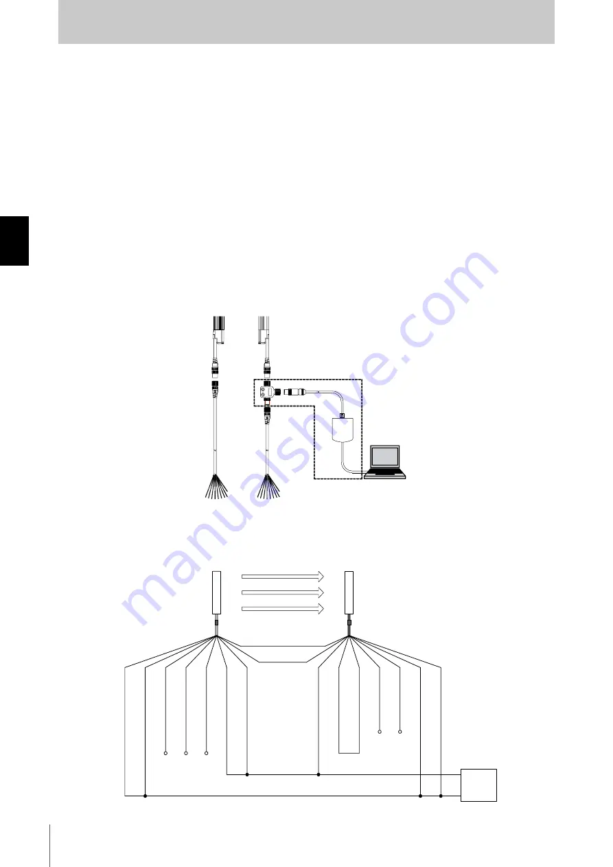
Connection Procedure
Connect your computer, communication unit, and F3SJ as shown below. You can connect a branch
connector either on the emitter or receiver end. Complete the wiring for F3SJ and turn it on, then
activate the setting software.
If a branch connector is difficult to attach due to devices layout or other reason, use an accessory
plugged dedicated cable to communication lines (+) and (-).
For details, see the help for the SD Manager.
Minimum Wiring for Setting
Minimum wiring required to check the operation of the F3SJ
(Wiring for auto reset mode and deactivated external device monitoring function)
PC
PC Tool for F3SJ
F39-GWUM
(Optional accessory)
Interlock selection input(White)
0V(Blue)
Shield
Open
Open
Open
Open
Open
+24V DC
0 V
Power
supply
Emitter
Receiver
(Grey)Communication line (+)
(Pink)
Communication line (-)
Shield
Auxiliary output 2(Red)
Test input(Green)
Reset input(Yellow)
24V(Brown)
24V(Brown)
External device monitoring input (Red)
Auxiliary output 1(Yellow)
0V(Blue)
Safety output 1(Green)
Safety output 2(White)
Courtesy
of
CMA/Flodyne/Hydradyne
▪
Motion
Control
▪
Hydraulic
▪
Pneumatic
▪
Electrical
▪
Mechanical
▪
(800)
426-5480
▪
www.cmafh.com


