background image

1-5-40

C8150

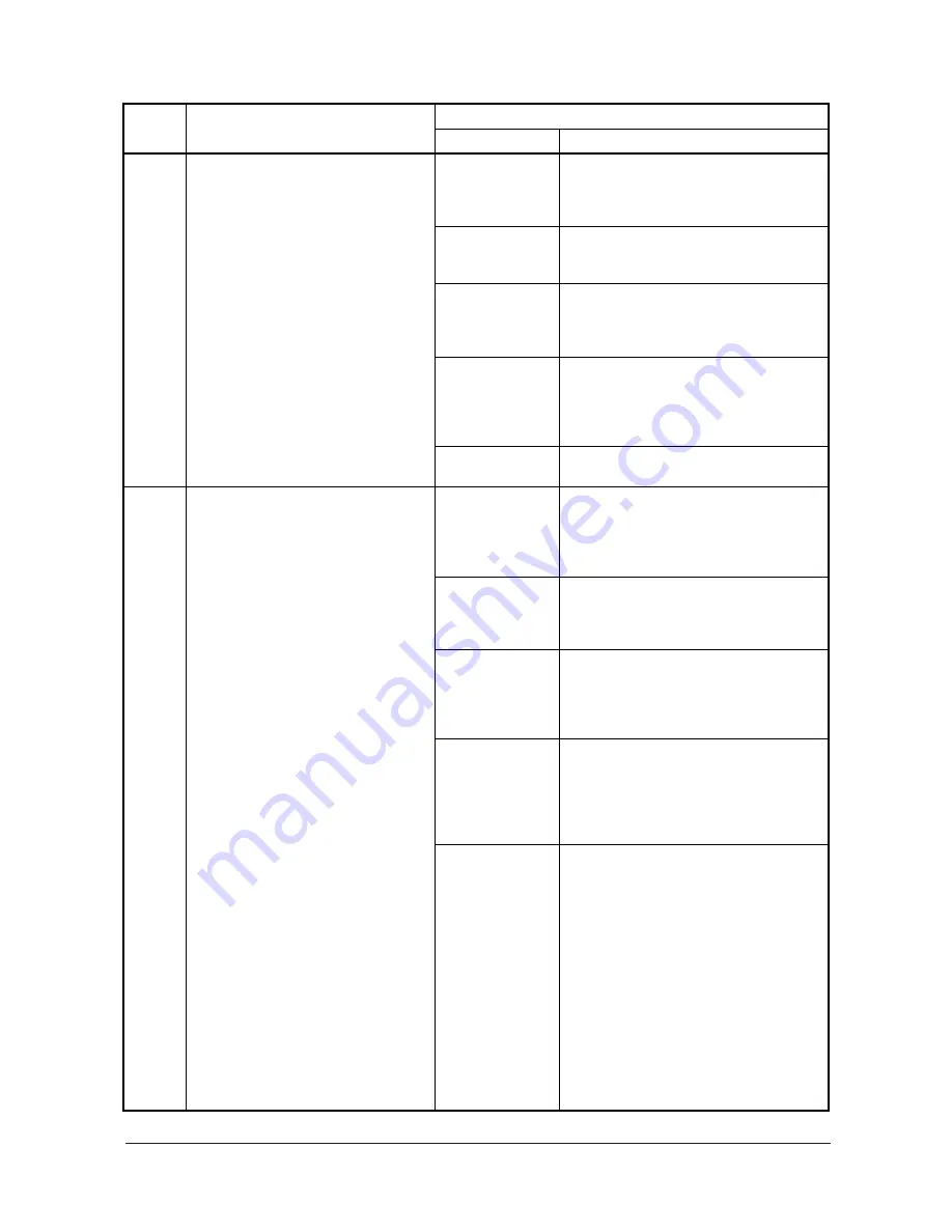
Document finisher* multi job tray 
problem

• When the multi job tray is not detected 

by the multi job tray upper limit detec-
tion sensor within 15 s from the 
moment it starts ascending.

• During multi job tray descent, the multi 

job tray upper limit detection sensor 
does not turn off within 500 ms after it 
turns on.

Loose connection 
of the multi job tray 
elevation motor 
connector.

Reinsert the connector. Also check for conti-
nuity within the connector cable. If none, 
remedy or replace the cable.

Malfunction of the 
multi job tray ele-
vation motor.

Replace the multi job tray elevation motor 
and check for correct operation.

Malfunction of the 
multi job tray upper 
limit detection sen-
sor.

Replace the multi job tray upper limit detec-
tion sensor and check for correct operation.

Loose connection 
of the multi job tray 
upper limit detec-
tion sensor con-
nector.

Reinsert the connector. Also check for conti-
nuity within the connector cable. If none, 
remedy or replace the cable.

Defective finisher 
main PWB.

Replace the finisher main PWB and check 
for correct operation.

C8170

Document finisher* front upper side 
registration guide problem

• During initialization, the front upper 

side registration guide is not detected 
in the home position within 1.5 s after 
the guide returns to the home position.
JAM87 is indicated the first time this 
problem occurs. If the problem occurs 
after initialization when the front cover 
is opened and closed, the problem is 
in the front upper side registration 
guide.

• When the front upper side registration 

guide is operated from the home posi-
tion, the front upper side registration 
home position sensor does not turn off 
within 500 ms.

Loose connection 
of the front upper 
side registration 
guide motor con-
nector.

Reinsert the connector. Also check for conti-
nuity within the connector cable. If none, 
remedy or replace the cable.

Malfunction of the 
front upper side 
registration guide 
motor.

Replace the front upper side registration 
guide motor and check for correct operation.

Malfunction of the 
front upper side 
registration guide 
home position sen-
sor.

Replace the front upper side registration 
guide home position sensor and check for 
correct operation.

Loose connection 
of the front upper 
side registration 
guide home posi-
tion sensor con-
nector.

Reinsert the connector. Also check for conti-
nuity within the connector cable. If none, 
remedy or replace the cable.

Defective finisher 
main PWB.

Replace the finisher main PWB and check 
for correct operation.

Code

Contents

Remarks

Causes

Check procedures/corrective measures

          Service Manual                                                            Y104350-7       

Summary of Contents for d-Copia 600

Page 1: ...d Copia 600 d Copia 800 Color Printer SERVICE MANUAL Code Y104350 7...

Page 2: ...PUBLICATION ISSUED BY Olivetti S p A 77 Via Jervis 10015 Ivrea TO Italy Copyright 2006 Olivetti All rights reserved...

Page 3: ...y is incorrectly replaced Replace only with the same or equivalent type recommended by the manufacturer Dispose of used batteries according to the manufacturer s instructions CAUTION Double pole neutr...

Page 4: ...This page is intentionally left blank iv Service Manual Y104350 7...

Page 5: ...ure the safety of their customers their machines as well as themselves during maintenance activities Service personnel are advised to read this booklet carefully to familiarize themselves with the war...

Page 6: ...UTION Bodily injury or damage to property may result from insufficient attention to or incorrect compliance with warning messages using this symbol Symbols The triangle symbol indicates a warning incl...

Page 7: ...This may cause fire or electric shock Do not install the copier near a radiator heater other heat source or near flammable material This may cause fire Allow sufficient space around the copier to all...

Page 8: ...s check that the copier is correctly connected to an outlet with a ground connection Check that the power cable covering is free of damage Check that the power plug is dust free If it is dirty clean i...

Page 9: ...and missing screws Check that all the caution labels that should be present on the machine according to the instruction handbook are clean and not peeling Replace with new ones if necessary Handle gre...

Page 10: ......

Page 11: ...Setting initial copy modes 1 3 12 1 3 3 Installing the key counter option 1 3 13 1 3 4 Installing the document finisher option 1 3 15 1 3 5 Installing the side feeder option 1 3 24 1 3 6 Installing th...

Page 12: ...is turned on 1 5 57 2 The developing motor does not operate C2100 1 5 57 3 The drive motor does not operate C2200 1 5 57 4 The fuser motor does not operate C2300 1 5 57 5 The transfer motor does not...

Page 13: ...The message requesting paper to be loaded is shown when paper is present in cassette 4 1 5 66 60 The message requesting paper to be loaded is shown when paper is present on the MP tray 1 5 67 61 The s...

Page 14: ...refitting the scanner wires 1 6 37 2 1 Detaching the scanner wires 1 6 37 2 2 Fitting the scanner wires 1 6 39 3 Detaching the laser scanner unit 1 6 42 4 Detaching and refitting the ISU reference 1 6...

Page 15: ...itting the developing front fan filters 1 6 97 4 Detaching and refitting the image formation fan filter 1 6 98 5 Detaching and refitting the front cover filters 1 6 99 6 Detaching and refitting the oz...

Page 16: ...WB 2 3 45 2 3 11 DP main PWB 2 3 49 2 4 Appendixes Chart of image adjustment procedures 2 4 1 Image quality 2 4 4 Maintenance parts list 2 4 5 Periodic maintenance procedures 2 4 7 Maintenance kits 2...

Page 17: ...ts min A3 11 x 17 40 sheets min B4 257 x 364 mm 8 1 2 x 14 50 sheets min B5 80 sheets min B5R 58 sheets min When the document processor is used at 100 magnification A4 11 x 8 1 2 80 sheets min 60 cpm...

Page 18: ...W x 30 13 16 D Functions Selecting image quality Adjusting exposure Auto zoom Manual zoom Preset zoom XY zoom Duplex mode Split mode Sort mode Auto paper selection Offset mode Combine mode Margin mod...

Page 19: ...processor DP 4 Cassette 1 5 Cassette 2 6 Cassette 3 7 Cassette 4 8 MP tray 9 Paper width guides 10 MP tray extension 11 Right cover 12 Handles 13 Main power switch 14 Main power switch cover 15 Docum...

Page 20: ...Document processor top cover 27 Ejection guide 28 Document processor angle adjustment lever 29 Original eject table 30 Toner container 31 Toner container release lever 32 Paper conveyor 33 Knob A1 34...

Page 21: ...gement key indicator 6 Print management key indicator 7 Repeat copy key indicator 8 Job build key indicator 9 Auto selection key indicator 10 System menu counter key 11 Job accounting key 12 Interrupt...

Page 22: ...al path 1 Paper feed section 2 Main charging section 3 Optical section 4 Drum section 5 Developing section 6 Transfer section 7 Cleaning section 8 PTC section 9 Fuser section 10 Feedshift and eject se...

Page 23: ...system 1 Optical section Figure 1 1 5 1 Scanner motor 2 Belt scanner 3 Drum pulley 4 Gear Z36 5 Gear Z18 39 6 Pulley scanner 7 Front Rear wire scanner 8 Pulley moving idle 9 Pulley scanner 10 Pulley...

Page 24: ...aper feed motor 3 2 Gear cassette feed 3 Upper gear paper feed 4 Joint drive 5 Gear 16 idle 6 Pulley leading feed 7 Paper feed motor 4 8 Gear cassette feed 9 Upper gear paper feed 10 Joint drive 11 Ge...

Page 25: ...d 7 Pulley deck 8 Pulley deck 9 Joint drive 10 Gear feed 11 Upper gear paper feed 12 Gear 16 idle 13 Pulley Leading feed 14 Paper feed motor 2 15 Joint drive 16 Upper gear paper feed 17 Gear feed 27 1...

Page 26: ...vertical feed 3 Pulley 26 vertical feed 4 Gear 32 vertical feed 5 Gear 38 vertical feed 6 Gear 38 vertical feed 7 Gear 38 vertical feed 8 Pulley 32 vertical feed 9 Gear 38 vertical feed 10 Gear 38 ver...

Page 27: ...1 1 11 6 Drive system 6 MP tray paper feed Figure 1 1 10 1 MP feed motor 2 Gear 54 MP tray 3 Gear 54 MP tray 4 Gear 44 MP tray Y104350 7 Sevice Manual...

Page 28: ...Gear 47 feed 3 Gear 21 feed 4 Gear Z18H feed 5 Gear Z18H Z18S feed 6 Gear 16 registration 7 Feed motor 8 Gear 43 feed 9 Gear 25 feed A 10 Gear 16 registration 11 Pulley 26 one way feed 12 Pulley 26 o...

Page 29: ...L 8 Coupling CL drive 9 Developing motor 10 Gear 44 11 Gear 40 DLP 12 Gear 25 DLP 13 Gear 70 DLP 14 Coupling DLP drive 15 Gear 64 DLP 16 Gear 30 50 joint 17 Gear 30 50 joint 18 Gear 40 DLP joint 1 Gea...

Page 30: ...Gear 88 fuser 9 Gear 40 fixing 10 Gear 19 fixing 11 Coupling fixing joint 12 Gear 133 duplex 13 Gear 71 duplex 14 Gear 29 duplex 15 Gear 19 33 eject 16 Pulley 20 17 Pulley 24 eject 18 Belt eject driv...

Page 31: ...r DU 17 7 Pulley 24 24 DU conveying 8 Pulley DU tension 9 Belt rear feed 10 Gear 37 24 DU conveying 11 Gear 27 24 one way L 12 Pulley 30 DU 13 Pulley 30 DU 14 Belt front drive 1 Gear 33 conveying idle...

Page 32: ...1 1 16 10 Drive system 10 Toner motor drive train Figure 1 1 17 1 Toner motor 2 Gear Z70 Z16S 3 Gear Z56S Z20S 4 Gear 38 5 Gear joint CONT 6 Coupling container Service Manual Y104350 7...

Page 33: ...r 20 15 Joint PF drive 16 DP lift motor 17 Gear 69 joint 18 Gear 20 65 idle 19 Gear 20 joint 20 Gear 20 65 idle 21 Gear lift 55 22 Gear CIS roller 20 23 Gear CIS idle 21 24 Gear CIS idle 21 25 Gear CI...

Page 34: ......

Page 35: ...9 5 A 4 Power source frequency 50 Hz 2 60 Hz 2 5 Installation location Avoid direct sunlight or bright lighting Ensure that the photo conductor will not be exposed to direct sunlight or other strong...

Page 36: ...1 2 2 Figure 1 2 1 Installation dimensions a d c e f b 30 60 a 680 mm 26 3 4 b 783 mm 30 13 16 c 1190 mm 46 7 8 d 1860 mm 73 3 16 e 1465 mm 57 11 16 f 1530 mm 60 3 16 Service Manual Y104350 7...

Page 37: ...ove the screws Taking out the machine Start Connecting the power cord Initial setting for the developer Make test copies Installing the guide case Attaching the language label 230 V specifications onl...

Page 38: ...case 11 Upper case 12 Machine cover 13 DP spacer 14 Deck spacers 15 Cassette spacers 16 Sheet 17 DP sheet 18 Rear sheets 19 Hinge joints 20 Plastic bag 21 Operation guide 22 Casette size plates 23 Ope...

Page 39: ...r the upper right spacer the outer case and the supports 2 Cut four tapes of the skid each corner 3 Cut each tape which locks the slope and the spacer 4 Rotate slopes as shown in the figure and make t...

Page 40: ...t the handles on machine left and right 6 Lift the machine each left and right one side and then remove the lower left and right spacers 7 Move the machine alongside slopes to slide to the floor Figur...

Page 41: ...or light source unit 1 and pin for light source unit 2 Figure 1 3 5 Remove the tapes pins spacers and sheet DP spacer Tape Tapes Tape DP sheet Tape Tapes Tapes Tapes Tape Tapes Pin for light source un...

Page 42: ...the tape of power cord Figure 1 3 6 4 Remove four tapes and two rear sheets Figure 1 3 7 5 Open the DP and then remove three tapes and sheet Figure 1 3 8 Tapes 120 V specifications 230 V specificatio...

Page 43: ...ssette 1 and then remove the guide case Figure 1 3 9 8 Pull out cassette 3 and 4 then remove two cassette spacers and tapes Figure 1 3 10 1 Open the front cover and remove two screws Figure 1 3 11 Dec...

Page 44: ...1 3 8 1 Pull out the paper conveying unit 2 Remove two tapes from the transfer section Figure 1 3 13 3 Refit the conveying unit Remove the tapes of transfer section Tape Tape Service Manual Y104350 7...

Page 45: ...shake it vertically at least ten times to dis tribute the toner evenly 5 Turn the toner container upside down and shake it vertically at least ten times 6 Hold the toner container horizontally and sh...

Page 46: ...l count up from 0 and will become an instal lation end by 180 RESULT Result of the installation 0 During installation 1 Installation is successful 2 Installation is failed If the installation is faile...

Page 47: ...ower switch label Figure 1 3 18 Figure 1 3 19 1 Attach the guide case to the machine right Figure 1 3 20 Attaching the language label 230 V specifications only MP label DP labels DP label Main power s...

Page 48: ...h Year metric U277 Setting auto application change time 30s U281 Setting stamp mode ON OFF OFF U326 Setting the black line cleaning indication ON U327 Setting the drawer heater ON OFF Drawer heater OF...

Page 49: ...re turning off the main power switch And then unplug the power cable from the wall outlet Turning off the main power switch before pressing the Power key to off may cause damage to the equipped hard d...

Page 50: ...d to the key counter cover retainer on the machine using the screw Figure 1 3 22 7 Insert the key counter into the key counter socket assembly 8 Connect the power cord and turn the main power switch o...

Page 51: ...in power switch And then unplug the power cable from the wall outlet Turning off the main power switch before pressing the Power key to off may cause damage to the equipped hard disk Procedure 1 Insta...

Page 52: ...nter of the cover Figure 1 3 25 4 Fix two grounding plate B with the M4 x 8 tap tight S screw to the front back hooks of the finisher Figure 1 3 26 5 Open the front cover 6 Remove the screw raise the...

Page 53: ...e finisher and the two short pins align with the holes of the connecting rail 10 Hooking the hooks onto the brackets at the bottom of the machine connect the finisher to the machine Figure 1 3 29 11 P...

Page 54: ...four blue screws locking each of the two separate retainers to the intermediate tray and detach both retainers 14 Pull out the intermediate tray Figure 1 3 32 15 Remove the tape Figure 1 3 33 Link le...

Page 55: ...four tapes Figure 1 3 35 18 Load two staple cartridges into the staple holders and press down on them until they lock securely into place 19 Close the intermediate tray return it to its original posi...

Page 56: ...by inserting it from above into the hole on the finisher Figure 1 3 37 23 Remove the screw and then remove the sig nal cable cover Figure 1 3 38 24 Connect the signal cable to the connector of the ma...

Page 57: ...lower rear cover of the machine 27 Fit the clamp on non covered part of the sig nal cable to secure the cable to the lower rear cover with the M3 x 10 tap tight S screw 28 Plug the machine s power ca...

Page 58: ...tate the lower lever by one mark in the direction of the higher numbers There are 5 marks 3 Close the front cover 4 Run paper through the machine and check if it is still curled downward 5 Repeat step...

Page 59: ...er that has been cen terfold stapled with the inside faced down as shown in the illustration Check that the paper is stapled at the center 3 If the staple position is off enter mainte nance mode and r...

Page 60: ...unplug the power cable from the wall outlet Turning off the main power switch before pressing the Power key to off may cause damage to the equipped hard disk Procedure 1 Cut out the four hole covers...

Page 61: ...ght cover 7 Open the right cover Figure 1 3 50 8 Install two M4 x 6 TP screws in the long holes of the fixing plate Align the V groove of the fixing plate with the center of the guide of the machine F...

Page 62: ...or bracket Figure 1 3 52 10 Set the side feeder on the machine and connect its signal cable to the connector on the back of the machine 11 Attach clamp to the lower rear cover of the machine to fasten...

Page 63: ...on its main power switch 2 Enter maintenance mode and run U034 Adjusting the print start timing 3 Press the interrupt key select the side feeder for the test print mode and then print a test pattern...

Page 64: ...cedure Install the printer board 1 Remove three screws and then remove the cover Figure 1 3 56 2 Slide in the printer board along the rails and then secure it with the three screws and two M4 x 8 tap...

Page 65: ...al interface to the printer board using the two pins 4 Slide in the printer board along the rails and then secure it with the five screws Take care that the power cord does not come into contact the f...

Page 66: ...crew of the lower rear cover Fasten all the cables with the clamp and tighten the M3 screw to fix the clamp Make sure that the clamp is facing as shown in the figure Figure 1 3 62 M3 screw Clamp Servi...

Page 67: ...ews and then remove the hole cover 2 Remove the nine screws and then remove the rear middle cover Figure 1 3 63 3 Remove the eight screws and then remove the right sequence cover Figure 1 3 64 4 Firml...

Page 68: ...crew of the lower rear cover Fasten all the cables with the clamp and tighten the M3 screw to fix the clamp Make sure that the clamp is facing as shown in the figure Figure 1 3 66 M3 screw Clamp Servi...

Page 69: ...e to the equipped hard disk If the machine is using a hard disk already installing the security kit will not erase hard disk data automatically To delete data you need to consult your customer Refer t...

Page 70: ...eturn the right sequence cover and rear middle cover to their original positions Figure 1 3 69 6 Plug the machine into a power outlet and turn on its main power switch 7 Confirm that the hard disk ico...

Page 71: ...1 using the cursor up down keys or numeric keys and press the start key Enter the maintenance item number using the cursor up down keys or numeric keys The selected maintenance item is run Press the s...

Page 72: ...operation of the fan motors U051 Adjusting the amount of slack in the paper Plain paper Amount of slack for low speed conveying Amount of slack for high speed conveying Amount of slack for duplex low...

Page 73: ...mode Photo mode 0 0 0 0 0 0 U099 Adjusting original size detection ORIGINAL LIGHT SOURCE WAIT TIME A4R AREA 72 72 150 240 High voltage U100 Adjusting the surface potential 82 20 0 U101 Setting the oth...

Page 74: ...king the cleaning count U194 Setting the fuser web drive 30 U196 Turning the fuser heater on U198 Setting the fuser phase control OFF 120 V ON 220 240 V U199 Displaying fuser heater temperature Operat...

Page 75: ...heater ON OFF OFF OFF U330 Setting the number of sheets to enter stacking mode during sort operation 201 U331 Switching the paper ejection mode Face up ejection U332 Setting the size conversion facto...

Page 76: ...e waste toner box count U922 Checking clearing the solenoid count value U925 Checking clearing the system error counts U927 Clearing the all copy counts and machine life counts U928 Checking machine l...

Page 77: ...When output is complete the screen for selecting an item is displayed Completion Press the stop clear key at the screen for selecting an item The screen for selecting a maintenance item No is display...

Page 78: ...as shown below To move the cursor press Left or Right in the bottom row 2 Press the start key The telephone number is set and the screen for selecting a maintenance item No is displayed Completion To...

Page 79: ...tion is simulated without paper under the set conditions When operation is complete the screen for selecting an item is displayed 6 To stop continuous operation press the stop clear key Completion Pre...

Page 80: ...the start key All data in the backup memory is initialized and the default setting for the inch spec ifications is registered When initializing is complete the machine automatically returns to the sa...

Page 81: ...up data is initialized When initializing is complete the machine automatically returns to the same status as when the main power switch is turned on Completion To exit this maintenance item without ex...

Page 82: ...backup data of the EEPROM which was transferred with the U026 to flash memory Purpose To use after the main PWB replaced Method 1 Press the start key The screen for executing is displayed 2 Press EXE...

Page 83: ...This page is intentionally left blank...

Page 84: ...high speed PF MOT3 H Paper feed motor 3 PFM3 is turned ON high speed PF MOT4 H Paper feed motor 4 PFM4 is turned ON high speed VF MOT H The vertical feed motor VFDM is turned ON high speed PF MOT1 Pap...

Page 85: ...witch ESW FEED B SW D Feed switch 2 FSW2 LCF SW A Deck conveying switch 1 DKCSW1 LCF SW B Deck conveying switch 2 DKCSW2 FEED C SW Feed switch 3 FSW3 FEED D SW Feed switch 4 FSW4 FEED E SW Feed switch...

Page 86: ...area for copying on folio paper Purpose To prevent cropped images on the trailing edge or left right side of copy paper by setting the actual printing area for folio paper Method Press the start key...

Page 87: ...The value is set 4 Press the interrupt key 5 Press the start key to output the test pattern 6 Open the front cover 7 Pull the duplex unit out and check the position of duplex side registration guide...

Page 88: ...are change at the same time 4 Press the start key The value is set Interrupt copy mode While this maintenance item is being executed a VTC pattern shown below is output in interrupt copy mode Correct...

Page 89: ...s the start key The screen for executing is displayed Setting 1 Select ON or OFF The selected item is displayed in reverse Initial setting OFF 2 Press the start key The setting is set Maintenance item...

Page 90: ...elected Completion Press the stop clear key at the screen for selecting an item The screen for selecting a maintenance item No is displayed Caution The following settings are also reset to the initial...

Page 91: ...creen for selecting a maintenance item No is dis played U064 Adjusting the CCD level Description Adjusts the CCD level Purpose To adjust when density difference due to CCD is generated between both si...

Page 92: ...e screen for selecting an item 5 Select the Scanning position using the cursor up down keys 6 Press the start key The value is set 7 Set the original the one which density is known in the document pro...

Page 93: ...d conditions 5 To stop operation press the stop clear key Completion Press the stop clear key with the scanning operation stopped The screen for selecting a maintenance item No is displayed Maintenanc...

Page 94: ...d Setting 1 Change the setting using the cursor up down keys Increasing the setting makes the luminosity higher and decreasing it makes the luminosity lower 2 Press the start key The value is set Inte...

Page 95: ...p clear key is pressed during auto adjustment adjustment stops and no settings are changed U080 Adjusting exposure in toner economy mode Description Adjusts the image density in the eco print mode Pur...

Page 96: ...for selecting an item 2 Change the value using the cursor up down keys 3 Press the start key The value is set Setting 1 Select BLACK LINE at the screen for selecting an item 2 Select CLEAR 3 Press th...

Page 97: ...e interrupt key The copy mode screen is displayed 5 Press the start key A MIP PG pattern is output Completion Press the stop clear key The screen for selecting a maintenance item No is displayed Maint...

Page 98: ...stops Should this happen determine the details of the problem and either repeat the pro cedure from the beginning or adjust the remaining items manually by running the corresponding main tenance items...

Page 99: ...screen for selecting an item press the stop clear key Setting Gradient in text mode 1 Select the item to be set The selected item is displayed in reverse 2 Change the setting value using the cursor up...

Page 100: ...an item press the stop clear key Interrupt copy mode While this maintenance item is being executed copying from an original is available in the interrupt copying mode Completion Press the stop clear...

Page 101: ...the original size judgment time 1 Adjust the preset value using the or keys A larger value increases the original size judgment time and a smaller value decreases it 2 Press the start key The value is...

Page 102: ...e when poor image quality is caused by dirt in the main charger wire 3 Press the start key The value is set Setting the potential compensation 1 Select START ADJ GAIN at the screen for selecting an it...

Page 103: ...an item 2 Press the start key Drive motor transfer motor and developing motor are turned on and then cleaning lamp and PTC unit is turned on Interrupt copy mode While this maintenance item is being ex...

Page 104: ...ct 0 OFF or 1 ON The selected item is displayed in reverse Initial setting OFF If ON is selected when the preset number of sheets for charger cleaning operation intervals is exceeded during copying th...

Page 105: ...t key The current counts of the transfer counter is displayed Clearing 1 Press the reset key and press the start key The count is cleared Completion To exit this maintenance item without changing the...

Page 106: ...cibly Description Replenishes toner forcibly until the toner sensor output value reaches the toner feed start level Purpose Used when the toner empty is detected frequently Method 1 Press the start ke...

Page 107: ...he user Start Press the start key The screen for selecting an item is displayed Method Toner applying operation mode 1 Select MODE at the screen for selecting an item 2 Change the setting using the cu...

Page 108: ...g a maintenance item No is displayed U157 Checking the developing drive time Description Displays the developing drive time for checking a figure which is used as a reference when correcting the toner...

Page 109: ...emperature aging time after secondary stabilization control temperature adjustment in duplex copying and time from power on to stabi lization of fusing PAGE2 Control temperature adjustment in duplex c...

Page 110: ...tion Purpose To prevent accidents due to an abnormally high fuser temperature Method 1 Press the start key The screen for executing is displayed 2 Press EXECUTE on the touch panel 3 Press the start ke...

Page 111: ...ion Sets the use of fuser phase control to reduce electrical noise generated by the copier Purpose Normally no change is necessary If electrical noise generated by the copier causes flickering of the...

Page 112: ...panel Purpose To automatically correct the display positions on the touch panel after it is replaced Method 1 Press the start key The screen for executing is displayed and the key displayed at the upp...

Page 113: ...item if a key card or key counter is installed Method Press the start key The screen for selecting an item is displayed Setting 1 Select the optional counter to be installed using the cursor up down...

Page 114: ...er placed in cassette 1 cassette 2 or optional side feeder is changed Method Press the start key The screen for selecting an item is displayed Setting 1 Press the start key The screen for executing is...

Page 115: ...finisher Purpose To be set as required according to the user Method Press the start key The screen for selecting an item is displayed Setting 1 Select the item to be set The selected item is displaye...

Page 116: ...layed Setting 1 Change the setting using the cursor up down keys Initial setting 0 If the preset value is changed to 1 the number of sheets of a stack is limited to 1 500 in modes other than the stapl...

Page 117: ...belt motor PCBM L is turned on LGR_TEST Front rear upper side registration guide motor SRGM FU RU test operation for 11 x 17 size A3_TEST Front rear upper side registration guide motor SRGM FU RU tes...

Page 118: ...her Method 1 Press the start key The screen for selecting an item is displayed 2 Turn each switch ON manually When a switch is detected to be in the ON position the display for that switch will be hig...

Page 119: ...upper limit detection sensor MTULDS 1000_SW Main tray load 1000 detection sensor MTLDS 10 1500_SW Main tray load 1500 detection sensor MTLDS 15 JTRAY_LLT_SW Multi job tray lower limit detection senso...

Page 120: ...switch is detected the corresponding switch is displayed in reverse 3 To return to the screen for selecting an item press the stop clear key Completion Press the stop clear key at the screen for sele...

Page 121: ...er Method 1 Press the start key The screen for selecting an item is displayed 2 Select the motor to be operated When checking the side feeder lift motor SFLM operation set the paper to the side feeder...

Page 122: ...roper Setting the punch limit Sets the maximum number of punches possible in order to be informed of the timing for disposing of waste punch Decrease the value when using thick paper frequently Start...

Page 123: ...DDLE STAPLE ADJUST at the screen for selecting an item 2 Select the size to be set 3 Change the setting using the cursor up down keys If the staple position is displaced toward the ejection side copy...

Page 124: ...intenance item No Description Copy sample 1 Copy sample 2 Display Description Setting range Default setting Change in value A4R 8 5 x 11 Adjustment of center folding position for A4R 8 5 x 11 size 10...

Page 125: ...a maintenance item No is displayed Completion To exit this maintenance item without changing the current setting press the stop clear key The screen for selecting a maintenance item No is displayed U2...

Page 126: ...nitial settings are provided according to the destinations in the maintenance items below To change the initial settings in those items be sure to run maintenance item U021 after changing the destina...

Page 127: ...Turning auto start function ON OFF Description Selects if the auto start function is turned on Purpose Normally no change is necessary If incorrect operation occurs turn the function off this may sol...

Page 128: ...per jam occurs frequently in the optional document finisher when the number of copies is counted at the time of paper ejection copies are provided without copy counts The copy service provider cannot...

Page 129: ...H DATE YEAR for the inch specifications DATE MONTH YEAR for the metric specifications 2 Press the start key The setting is set and the screen for selecting a maintenance item No is displayed Completio...

Page 130: ...r up down keys The setting can be changed by 30 s per step 2 Press the start key The value is set and the screen for selecting a maintenance item No is displayed Completion To exit this maintenance it...

Page 131: ...Completion To exit this maintenance item without changing the current setting press the stop clear key The screen for selecting a maintenance item No is displayed U327 Setting the drawer heater ON OFF...

Page 132: ...key The setting is set and the screen for selecting a maintenance item No is displayed Completion To exit this maintenance item without changing the current setting press the stop clear key The scree...

Page 133: ...tem is displayed 2 Select ON or OFF Initial setting OFF 3 Press the start key The setting is set and the screen for selecting a maintenance item No is displayed Completion Press the stop clear key The...

Page 134: ...aintenance item without changing the current setting press the stop clear key The screen for selecting a maintenance item No is displayed U344 Setting the low power mode Description Changes the contro...

Page 135: ...7 Adjusting the laser output Description Adjusts the laser output power Purpose The setting need not be changed Method Press the start key The screen for adjustment is displayed Setting 1 Change the s...

Page 136: ...yed in reverse 3 Press the start key All data in the scanner NIC is initialized Completion To exit this maintenance item without executing initialization press the stop clear key The screen for select...

Page 137: ...enance item without changing the current setting press the stop clear key The screen for selecting a maintenance item No is displayed U508 Setting the LDAP Description Enables or disables an LDAP serv...

Page 138: ...an To FTP Description Sets whether or not scan to FTP setting is enabled if an optional network scanner is installed This maintenance mode is effective for only 120 V specifications Purpose According...

Page 139: ...k the paper jam status Also to clear the jam counts after replacing consumable parts Start Press the start key The screen for selecting an item is displayed Method Displays clears the jam counts 1 Sel...

Page 140: ...service call press the reset key and then press the start key The count is cleared Method Displays the total call for service counts 1 Select TOTAL COUNT in the screen for selecting an item The total...

Page 141: ...ting a maintenance item No is displayed U906 Resetting partial operation control Description Resets the service call code for partial operation control Purpose To be reset after partial operation is p...

Page 142: ...ter value Purpose To check the total counter value Method Press the start key The screen for total count value is displayed Completion Press the stop clear key The screen for selecting a maintenance i...

Page 143: ...d When clearing all counts the screen for selecting a maintenance item is displayed Completion To exit this maintenance item without changing the count press the stop clear key The screen for selectin...

Page 144: ...set key 2 Press the start key The count is cleared Completion To exit this maintenance item without changing the count press the stop clear key The screen for selecting a maintenance No item is displa...

Page 145: ...of the problem be sure to change the setting in OFF U954 Setting the type of cooling fan Description Sets the new or old type of cooling fan Purpose To change the setting according to the type of the...

Page 146: ...ting a maintenance item No is displayed U985 Displaying the developing unit history Description Indicates the past record of machine number and the developing counter Purpose To check the machine numb...

Page 147: ...for selecting an item is displayed The accumulated time of illumination for the exposure lamp is displayed in minutes Clearing 1 Select the item to be cleared 2 Press the reset key 3 Press the start k...

Page 148: ...copy count page 1 4 77 Press Copy Default Press Machine Default Start Make copy default settings page 1 4 78 Make machine default settings page 1 4 80 Press Print Report Output the report page 1 4 83...

Page 149: ...s the total copy counts of all departments and print the total in the form of job accounting reports The total copy count can be reset as necessary 1 Press Management Total The total copy count is dis...

Page 150: ...se 3 Default settings for copying Exposure mode Exposure mode changes the default for how the copier adjust how dark or light copying is made 1 Select Exposure Mode using the cursor up down keys and p...

Page 151: ...posure using the cursor up down keys and press Change 2 Press Lighter or Darker to adjust the exposure Setting range 3 to 3 Adjusting automatic exposure for scanning text doc uments Adjusts the scanni...

Page 152: ...ditional functions screen 1 Select Customize User Choice Customize Add function using the cursor up down keys and press Change 2 Highlight the menu item on the right side frame using the cursor up dow...

Page 153: ...n the size of the original document is cardstock or A6R select Cardstock or A6 When the size of the original document is B4R or Folio select B4 or Folio When the size of the original document is 11 x...

Page 154: ...the method for erasing the contents of the hard disk when the copier is equipped with the optional security kit 1 Select Hard Disk Delete Method using the cursor up down keys and press Change 2 Selec...

Page 155: ...ess End 4 Specify the password to the box 5 Select Password and press Change 6 Enter the password using the numeric keys and press Close The password should be a number up to 8 digits If you prefer no...

Page 156: ...e drum Refreshing the drum is recommended if images on copies appear blurred or warped or if blank areas appear Load the paper of size 11 x 8 1 2 or A4 or 11 x 17 or A3 in the MP tray 1 Press Drum ref...

Page 157: ...ction draw out the duplex unit When paper is jammed in the DP open the document processor top cover or document processor bottom cover Paper misfeed detection can be reset by opening and closing the r...

Page 158: ...s Figure 1 5 2 FSSW SBESW DUPCSW2 DKCSW1 DKCSW2 TIMSW1 RSW FSW2 FSW4 FSW5 TIMSW3 DUPSBM FDM DPTSW1 DPTSW2 TIMSW2 FSW3 DUPSRM DUPCSW3 DUPCSW1 DUPFSW ORM 1 OCM RM PFM2 PFM3 PFM4 PFM1 DUPSBM MPFDM ESW FS...

Page 159: ...ified time of less then A4 11 x 8 1 2 size 14 No paper feed from side feeder Side feeder feed switch SFFSW does not turn on within 2000 ms of the side feeder paper feed clutch SFPFCL turning on the cl...

Page 160: ...or 60 cpm of its turning on Feed switch 5 FSW5 does not turn on within specified time 1590 ms 1166 ms for 80 cpm 2046 ms 1166 ms for 60 cpm of timing switch 3 TIMSW3 turning off Description in is writ...

Page 161: ...700 ms of its turning on 32 Misfeed in registration Feed switch 1 FSW1 does not turn on within specified time 800 ms 586 ms for 80 cpm 1029 ms 586 ms for 60 cpm of feed switch 2 FSW2 turning on Descr...

Page 162: ...isfeed in fuser section 4 Exit switch ESW does not turn on within specified time 1350 ms for 80 cpm 1736 ms for 60 cpm of its turning on when paper is fed from cassette 4 44 Misfeed in fuser section 5...

Page 163: ...Misfeed in duplex convey ing section 3 Duplex conveying switch 3 DUPCSW3 does not turn on within specified time 750 ms for 80 cpm 1000 ms for 60 cpm of duplex conveying switch 2 DUPCSW2 turning on Du...

Page 164: ...s of its turning on When the intermediate tray paper conveying sensor ITPCS does not turn on within 2000 ms of the sub tray paper ejection sensor STPES turning on 85 Paper jam during ejection of stack...

Page 165: ...r entry sensor CUPES turning on 94 Jam in saddle eject sec tion The folded edge detection sensor FEDS is not turned on even if 5000 ms elapse after centerfold operation starts 95 Jam in saddle eject s...

Page 166: ...ally Replace feed switch 4 if indication of the corresponding sensor on the touch panel is not displayed in reverse Defective feed switch 5 Run maintenance item U031 and turn feed switch 5 on and off...

Page 167: ...ly and replace any deformed pulleys Defective timing switch 1 Run maintenance item U031 and turn the timing switch 1 on and off manually Replace the timing switch 1 if indication of the corre sponding...

Page 168: ...eeder feed clutch Check Broken side feeder feed switch actuator Check visually and replace the side feeder feed switch if its actua tor is broken Defective side feeder feed switch Run maintenance item...

Page 169: ...played in reverse Broken feed switch 4 actua tor Check visually and replace feed switch 3 if its actuator is broken Defective feed switch 4 Run maintenance item U031 and turn feed switch 3 on and off...

Page 170: ...rresponding sensor on the touch panel is not displayed in reverse 13 A paper jam in the paper feed section is indicated during copying multiple sheets in paper feed section 2 Jam code 25 Broken feed s...

Page 171: ...em U031 and turn deck conveying switch 1 on and off manually Replace deck conveying switch 1 if indication of the corresponding sensor on the touch panel is not displayed in reverse Broken deck convey...

Page 172: ...witch 1 if its actuator is broken Defective feed switch 1 Run maintenance item U031 and turn feed switch 1 on and off manually Replace feed switch 1 if indication of the corresponding sensor on the to...

Page 173: ...ated during copying jam in fuser section 1 Jam code 40 Defective exit switch Run maintenance item U031 and turn the exit switch on and off manually Replace the exit switch if indication of the corresp...

Page 174: ...and turn the exit switch on and off manually Replace the exit switch if indication of the correspond ing sensor on the touch panel is not displayed in reverse Broken feedshift switch actuator Check vi...

Page 175: ...tion of the corresponding sensor on the touch panel is not dis played in reverse 35 A paper jam in the duplex section is indi cated during copying jam 2 in duplex con veying section Jam code 65 Broken...

Page 176: ...e optional DP is indicated during copying jam in the original conveying section Jam code 73 Defective DP timing switch 1 Run maintenance item U244 and turn DP timing switch 1 on and off manually Repla...

Page 177: ...iding drum is dirty with paper powder Check and if it is dirty clean it The siding drum is deformed or worn Check and if it is deformed or worn fix or replace it Defective intermediate tray paper conv...

Page 178: ...ayed in reverse 52 A paper jam in the optional document finisher is indicated during copying jam in cover open Jam code 89 Defective upper cover switch If the voltage at CN3 3 on the finisher main PWB...

Page 179: ...ray detection sen sor if indication of the corresponding sensor on the touch panel is not displayed in reverse 57 A paper jam in the optional document finisher is indicated during copying jam in saddl...

Page 180: ...error is detected continuously however perform the operation shown in Table 1 5 1 If a system error occurs fre quently a fault may have occurred Check the details of the C call to take proper measures...

Page 181: ...nch motor problem C8030 Document finisher upper paper conveying belt problem C8040 Document finisher lower paper conveying belt problem C8140 Document finisher main tray problem C8150 Document finishe...

Page 182: ...main PWB and check for cor rect operation Device damage of EEPROM Contact the Service Administrative Division C0140 Backup memory EEPROM data problem Data damage of EEPROM Contact the Service Administ...

Page 183: ...rrect operation C0250 Network scanner board communica tion problem The response to the alive command to the network scanner transmitted once to 30 s does not come on the contrary three consecutive tim...

Page 184: ...times in succes sion Poor contact in the connector termi nals Check the connection of connector YC2 on the engine PWB and the connector on the duplex PWB Repair or replace if necessary Defective engin...

Page 185: ...y Defective side feeder main PWB Replace the side feeder main PWB Defective engine PWB Replace the engine PWB C0750 Document finisher EEPROM error A backup memory error is received in serial communica...

Page 186: ...t motor 2 connector terminals Reinsert the connector Also check for conti nuity within the connector cable If none repair or replace the cable Defective lift limit switch 2 Check if YC7 B8 on the deck...

Page 187: ...witch connec tor terminals Reinsert the connector Also check for conti nuity within the connector cable If none repair or replace the cable Defective side feeder main PWB Replace the side feeder main...

Page 188: ...high for 1 s 1 s after the fuser motor has turned on Poor contact in the fuser motor con nector terminals Reinsert the connector Also check for conti nuity within the connector cable If none remedy or...

Page 189: ...shading plate If the problem still occurs replace the scanner home position switch Poor contact of the connector termi nals Check the connection of connector YC4 on the scanner PWB and the continuity...

Page 190: ...em The polygon motor does not reach the stable speed within 20 s of the START signal turning on Poor contact in the polygon motor con nector terminals Reinsert the connector Also check for conti nuity...

Page 191: ...for cor rect operation Poor contact in connector termi nals Check the connection of connector YC8 on the main PWB and the continuity across the connector terminals Repair or replace if necessary C510...

Page 192: ...ounting state of the fuser ther mistor M and S If any problem is found repair it Defective fuser thermostat Replace the fuser thermostat see page 1 6 75 Installation defec tiveness on fuser heater L M...

Page 193: ...rossing signal C7200 Broken internal thermistor wire The thermistor output value is 4 5 V or more Poor contact in the connector termi nals Check the connection of connector YC23 on the engine PWB and...

Page 194: ...nd check for cor rect operation Defective finisher main PWB Replace the finisher main PWB and check for correct operation C8030 Document finisher upper paper con veying belt problem During initializat...

Page 195: ...ument finisher main tray problem When the main tray is not detected by the main tray upper limit detection sen sor or the main tray load detection sensor within 20 s from the moment it starts ascendin...

Page 196: ...stration guide is not detected in the home position within 1 5 s after the guide returns to the home position JAM87 is indicated the first time this problem occurs If the problem occurs after initiali...

Page 197: ...finisher main PWB Replace the finisher main PWB and check for correct operation C8190 Document finisher lower side regis tration guide problem During initialization the front rear lower side registrat...

Page 198: ...ont clincher motor connector Reinsert the connector Also check for conti nuity within the connector cable If none remedy or replace the cable Malfunction of the front clincher motor Replace the front...

Page 199: ...Also check for conti nuity within the connector cable If none remedy or replace the cable Defective center fold unit set switch Replace the centerfold unit set switch and check for correct operation D...

Page 200: ...or conti nuity within the connector cable If none remedy or replace the cable Malfunction of the centerfold blade motor Replace the centerfold blade motor and check for correct operation Malfunction o...

Page 201: ...d and write data does not match Data in the specified area of the backup memory does not match the specified values Defective DP main PWB Replace the DP main PWB and check for correct operation Device...

Page 202: ...52 See page 1 5 52 See page 1 5 52 See page 1 5 53 11 The leading edge of the image is consis tently mis aligned with the original 12 The leading edge of the image is spo radically mis aligned with th...

Page 203: ...1 5 47 21 There is a regu lar error between the leading edges of the original and copy image when the DP is used See page 1 5 56 Y104350 7 Sevice Manual...

Page 204: ...lace the engine PWB C Defective transfer high voltage PWB Replace the transfer unit see page 1 6 61 2 No LSU laser is output A Defective laser scanner unit Replace the laser scanner unit see page 1 6...

Page 205: ...ctor terminals of the exposure lamp make poor contact Reinsert the connector Also check for continuity within the connector cable If none remedy or replace the cable B Defective inverter PWB Check if...

Page 206: ...the connector cable If none remedy or replace the cable B Poor insertion transfer unit Reinstall the transfer unit C Continuity malfunction inside the transfer belt Check for continuity If none remed...

Page 207: ...separation roller Clean the DP separation roller 5 Foreign matter in the laser scanner unit Replace the laser scanner unit see page 1 6 42 6 Dirty CIS or CIS roller Clean the CIS or CIS roller 6 A bla...

Page 208: ...Clean the wire or if it is extremely dirty replace it see page 1 6 33 2 Defective exposure lamp Check if the exposure lamp light is distributed evenly If not replace the exposure lamp see page 1 6 34...

Page 209: ...page 1 6 25 2 Misadjusted scanner leading edge regis tration Readjust the scanner leading edge registration see page 1 6 54 3 Registration motor operating incorrectly Check the installation of the re...

Page 210: ...f machine default is proper see page 1 4 80 3 The paper is not loaded correctly Load the paper correctly 4 Defective fuser section Check the heat roller and press roller 5 Decrease of surface potentia...

Page 211: ...6 76 17 Image is out of focus Causes 1 Defective image scanning unit 2 Drum condensation Causes Check procedures corrective measures 1 Defective image scanning unit Replace the image scanning unit se...

Page 212: ...unit see page 1 6 50 20 There is a regular error between the centers of the original and copy image when the DP is used Causes 1 Misadjusted center line Causes Check procedures corrective measures 1 M...

Page 213: ...ance item U030 and check if YC8 3 on the duplex PWB goes low If not replace the duplex PWB 3 The drive motor does not operate C2200 Poor contact in the drive motor connector terminals Reinsert the con...

Page 214: ...em U030 and check if YC8 1 YC8 3 YC8 4 and YC8 6 on the deck PWB go low If not replace the deck PWB 7 Paper feed motor 2 does not operate Poor contact in paper feed motor 2 connector termi nals Reinse...

Page 215: ...ine PWB goes low If not replace the engine PWB 11 The MP feed motor does not operate Poor contact in the MP feed motor connector terminals Reinsert the connector Also check for continuity within the c...

Page 216: ...insert the connector Also check for continuity within the con nector cable If none remedy or replace the cable Broken PTC cleaning motor gear Check visually and replace the PTC cleaning motor if neces...

Page 217: ...tchback motor connector terminals Reinsert the connector Also check for continuity within the con nector cable If none remedy or replace the cable Broken duplex switchback motor gear Check visually an...

Page 218: ...es not operate Broken lamp fan motor coil Check for continuity across the coil If none replace the lamp fan motor Poor contact in lamp fan motor connector terminals Reinsert the connector Also check f...

Page 219: ...If none remedy or replace the cable Defective developing duct fan motor Run maintenance item U037 and check if the developing duct fan motor operates when YC5 2 on the engine PWB goes low If not repl...

Page 220: ...Reinsert the connector Also check for continuity within the con nector cable If none remedy or replace the cable 40 The MP solenoid does not operate Broken MP solenoid coil Check for continuity across...

Page 221: ...g lamp Defective engine PWB If the cleaning lamp turns on when YC5 5 on the engine PWB is held low replace the engine PWB 46 The exposure lamp does not turn on Poor contact in the expo sure lamp conne...

Page 222: ...or cable If none remedy or replace the cable Defective paper empty switch 1 Check if YC7 B5 on the deck PWB goes low when paper empty switch 1 is turned on with 5 V DC present at YC7 B6 on the deck PW...

Page 223: ...n nector terminals Reinsert the connector Also check for continuity within the con nector cable If none remedy or replace the cable Defective paper length size switch 2 Check if YC5 B3 on the cassette...

Page 224: ...k conveying switch 1 Run maintenance item U031 and turn deck conveying switch 1 on and off manually Replace deck conveying switch 1 if indication of the corresponding switch on the touch panel is not...

Page 225: ...otor does not operate Poor contact in the original registration motor connec tor terminals Reinsert the connector Also check for continuity within the con nector cable If none remedy or replace the ca...

Page 226: ...f none when the switch is on replace DP safety switch 1 Poor contact in DP safety switch 2 connector termi nals Reinsert the connector Also check for continuity within the con nector cable If none rem...

Page 227: ...Replace the original registration switch if indication of the corresponding switch on the touch panel is not displayed in reverse A piece of paper torn from an original is caught around DP timing swi...

Page 228: ...y Paper length guide in a cassette installed incorrectly Check the paper length guide visually and correct or replace if necessary Deformed paper length guide in a cassette Repair or replace if necess...

Page 229: ...ease the bearings and gears Check if the following motors are installed correctly paper feed motor 1 paper feed motor 2 paper feed motor 3 paper feed motor 4 and MP feed motor Check visually and remed...

Page 230: ...rty with paper powder Check and clean them with isopropyl alcohol if it is dirty Check if the DP separation roller is deformed Check visually and replace any deformed roller see page 1 6 83 Electrical...

Page 231: ...switch before pressing the Power key to off may cause damage to the equipped hard disk When handling PWBs printed wiring boards do not touch parts with bare hands The PWBs are susceptible to static ch...

Page 232: ...r the maintenance item number using the cursor up down keys or numeric keys The selected maintenance item is run Press the stop clear key Press the start key Start End Maintenance mode is entered The...

Page 233: ...re Detaching the deck conveying unit 1 Pull out the cassette 1 and 2 2 Open the front cover and pull the deck con veying unit out 3 While holding the lever in the direction of arrow remove the deck co...

Page 234: ...paper feed of cassette 1 from the deck conveying unit Figure 1 6 4 8 Remove the stop ring and slide the joint in the direction of the arrow 9 Open the primary paper feed of cassette 1 Figure 1 6 5 Pr...

Page 235: ...e the paper feed pulley and paper feed pulley gear from the paper feed pulley unit Figure 1 6 7 14 Remove the forwarding pulley shaft from the paper feed pulley unit and then remove the forwarding pul...

Page 236: ...he machine Figure 1 6 9 Detaching the separation pulley of cassette 1 16 Remove the separation pulley unit from the primary paper feed unit of cassette 1 Figure 1 6 10 17 Remove two stop rings bearing...

Page 237: ...e 19 Refit the separation pulley unit to the deck conveying unit 20 Refit the paper feed pulley unit to the pri mary paper feed unit of cassette 1 21 Insert the joint to the paper feed pulley shaft an...

Page 238: ...it and push down the unit in the direction of the arrow 26 Remove the paper feed unit from the pri mary paper feed unit of cassette 2 Figure 1 6 16 27 Remove the paper feed pulley and forward ing pull...

Page 239: ...ley see page 1 6 6 30 Refit the separation pulley unit to the pri mary paper feed unit of cassette 2 31 Refit the paper feed pulley unit to the pri mary paper feed unit of cassette 2 32 Close the prim...

Page 240: ...of an detaching and refitting procedure is given only a cassette 3 since cassettes 3 and 4 are the same feed units Procedure 1 Pull out cassette 1 3 and 4 2 Remove the screw and then remove the front...

Page 241: ...Detaching the paper feed pulley and forwarding pulley 7 Release the hook of the paper feed pulley unit and push down the unit in the direction of the arrow Figure 1 6 22 8 Remove the paper feed pulley...

Page 242: ...25 12 Clean or replace the paper feed pulley and forwarding pulley and then attach the pul leys to the paper feed pulley unit When replacing the paper feed pulley make sure that the one way clutch of...

Page 243: ...torque limiter fits in the separation pulley groove 16 Refit the separation pulley unit to the pri mary paper feed unit 17 Refit the paper feed pulley unit to the pri mary paper feed unit 18 Close the...

Page 244: ...f paper feed occur Does no paper feed occur No Select the cassette to be adjusted Remove the deck conveying unit or primary paper feed unit see page 1 6 3 or 1 6 10 Move the position of two springs in...

Page 245: ...five screws securing cassette 1 or 2 Select cassette 1 or 2 For output example 2 move cassette 1 or 2 in the direction of white arrow 4 Adjusting the center line for cassette 1 or 2 Perform the follo...

Page 246: ...damper counter clockwise for the removed levels The damper is adjustable to 2 level in both clockwise and counter clockwise directions Figure 1 6 33 Adjust to the center level The damper is at the ce...

Page 247: ...oping fan cover 2 Open the MP tray Figure 1 6 34 3 Remove the two pins and then remove the lower right rear cover Figure 1 6 35 4 Remove the screw and then remove the middle right cover Figure 1 6 36...

Page 248: ...5 Remove the connector and then remove the MP tray Figure 1 6 37 6 Remove the connector and two screws and then remove the MP unit Figure 1 6 38 MP tray Connector MP unit Connector Service Manual Y10...

Page 249: ...om the MP unit front and rear 3 Release the claws of the MP unit front and rear in the direction of the arrow 4 Remove the projections from the inserted parts and then divide the unit into upper and l...

Page 250: ...the joint in the direction of the arrow Figure 1 6 41 7 Remove two stop rings and bushes and then remove the MP paper feed pulley unit from the upper MP unit Figure 1 6 42 Joint MP solenoid lever Stop...

Page 251: ...per feed pulley unit Figure 1 6 44 12 Clean or replace the MP paper feed pulley and MP forwarding pulley and then attach the pulleys to the MP paper feed pulley unit When replacing the MP paper feed p...

Page 252: ...en remove the MP separation pulley Figure 1 6 46 16 Clean or replace the MP separation pulley and then attach the pulley to the MP separa tion pulley unit When replacing the MP separation pulley make...

Page 253: ...the upper MP unit 19 Assemble the upper and lower MP units 20 Refit the MP unit and MP tray When refitting the MP unit refit to insert the shaft of the machine in coupling at rear side 21 Refit the m...

Page 254: ...ing Remove the MP unit see page 1 6 17 Reverse the MP unit and then remove two springs Loosen two screws to move the position of each front back adjusting guide in the direction of the white arrow Fix...

Page 255: ...value of RCL ON DUP L is corrected when the sum total of the setting value of RCL ON L and RCL ON DUP L is less than 13 9 A setting value of RCL ON DUP L is corrected when the sum total of the settin...

Page 256: ...lear key Exit maintenance mode End 8 2 Adjusting the leading edge registration for duplex switchback copying Make the following adjustment if there is a regular error between the leading edge of the c...

Page 257: ...range initial setting LSUOUT 5 0 to 5 0 0 LSUOUT DUP 2 0 to 2 0 0 Changing the value by 1 moves the center line by 0 1 mm Select CASSETTE on the touch panel Touch panel display LSUOUT Center line adju...

Page 258: ...ng using the cursor up down keys Press the interrupt key Yes No Press the stop clear key Exit maintenance mode End Proceed to another mode Touch panel display LEAD Printer leading edge margin A Printe...

Page 259: ...at the registration roller for high speed conveying Plain Touch panel display BYPASS DATA Amount of slack at the registration roller for MP feed HIGH DUPLEX DATA Amount of slack at the registration r...

Page 260: ...f slack The new setting is stored Is the leading edge of the image missing or varying randomly copy example 1 Is the copy paper Z folded copy example 2 Increase the value using the cursor up key Press...

Page 261: ...r 3 Remove two screws and then pull out the image formation unit Figure 1 6 57 4 Remove two connectors and release the lock lever 5 Raise the rear of the main charger unit and slide the unit to machin...

Page 262: ...charger wire cleaning pad Follow the procedure below to replace the main charger wire cleaning pad Procedure 1 Remove the main charger unit see page 1 6 31 2 Remove the main charger grid 3 Remove fou...

Page 263: ...arger pin and spring and then remove the charger wire 5 Wind the new wire at 4 and 6 turns around one end of the charger spring and trim the end of the wire The length of the twists and the cut wire m...

Page 264: ...of the left hinge and then remove the retainer from DP 2 Open DP until it becomes perpendicular Figure 1 6 63 3 Remove two screws and then remove the upper right cover 4 Remove the contact glass Figur...

Page 265: ...lding the exposure lamp and then remove the lamp 9 Remove the wire guide from the wire of the exposure lamp Figure 1 6 67 10 Replace the exposure lamp 11 After letting the wire of the exposure lamp pa...

Page 266: ...ire to the connector 3 At this time be careful to be unable to twist the wire Figure 1 6 69 14 Attach the new band in order to bind with the marked position of the wire of the exposure lamp 15 Insert...

Page 267: ...cover to machine rear Remove the upper left cover Figure 1 6 71 2 Remove the exposure lamp see page 1 6 34 3 Remove the DP see page 1 6 82 4 Remove the upper rear cover Figure 1 6 72 5 Remove the stap...

Page 268: ...ve the slit holder plate and slit glass Figure 1 6 75 9 Remove each screw and then remove the front and rear wire holder plates from the mirror 1 frame Figure 1 6 76 Inserted parts Operation unit uppe...

Page 269: ...When fitting the wires be sure to use those specified below Machine front gray Machine rear black Fitting requires the following tools Frame securing tools Scanner wire stoppers Procedure 1 Move the m...

Page 270: ...8 Wind the scanner wires five turns from the inner toward the hole in the drum 6 9 Install the scanner wire stoppers to the scanner wire drum to fix the wires 7 10 Loop the scanner wires around the gr...

Page 271: ...he positioning holes at the front and rear of the scanner unit to secure the frames in position 20 Secure the two screws from each of the frame securing tools and then the tools 21 Hold the wires and...

Page 272: ...and then remove the left cover 4 Remove the staple tray operation unit right cover operation unit left cover and operation unit upper cover see page 1 6 37 5 Move the mirror 1 frame to the machine lef...

Page 273: ...e laser scan ner unit from holes inside the laser scanner unit Figure 1 6 86 10 Raise the laser scanner unit and release two inserted parts Remove the laser scanner unit from machine left Figure 1 6 8...

Page 274: ...rt three claws of upper left frame to the inserted parts of inside the machine Refit the upper left frame Figure 1 6 89 14 Refit three bands of black wire 15 Refit the operation unit upper cover opera...

Page 275: ...5 18 Connect the power cord and turn the main power switch on 19 Enter the maintenance mode 20 Run the maintenance item U472 to enter the numerical value indicated by the LSU cover Y104350 7 Sevice Ma...

Page 276: ...s Two positions pins Procedure 1 Remove two screws of hinge retainer at the rear side of the left hinge and then remove the retainer from DP 2 Remove the upper right cover and contact glass see page 1...

Page 277: ...ition ISU at the positioning hole 7 indi cated on the scanner unit and inset two positioning pins Figure 1 6 92 8 Refit the ISU using four screws and then remove two positions pins 9 Refit three flexi...

Page 278: ...e longitudinal squareness reference Perform the following adjustment if the copy image is longitudinally skewed longitudinal squareness is not obtained Caution Adjust the amount of slack in the paper...

Page 279: ...LSU adjustment plate For output example 1 move the LSU adjustment plate in the direction of the black arrow For output example 2 move the LSU adjustment plate in the direction of the white arrow 6 Ad...

Page 280: ...ect Place the original on the contact glass 6 2 Adjusting the position of the ISU Perform the following adjustment if the leading and trailing edges of the copy image are laterally skewed lateral squa...

Page 281: ...or up key For copy example 2 decrease the value using the cursor down key Press the start key The new setting is stored Select MAIN SCAN ADJ main scanning direction Press the start key Press the stop...

Page 282: ...ss the start key The new setting is stored Press the start key Press the stop clear key Select SUB SCAN ADJ auxiliary scanning direction 8 Adjusting magnification of the scanner in the auxiliary scann...

Page 283: ...de second face 7 to 7 0 Changing the value by 1 moves Center line for simplex copy mode 0 17 mm Center line for duplex copy mode second face 0 084 mm End Touch panel display ADJUST DATA Center line fo...

Page 284: ...Changing the value by 1 moves the center line by 0 17 mm Touch panel display ADJUST DATA Leading edge registration ADJUST DATA2 Leading edge registration second face Select ADJUST DATA or ADJUST DATA...

Page 285: ...adjusted on the touch panel Are the margins correct Press the interrupt key Touch panel display A MARGIN Scanner left margin B MARGIN Scanner leading edge margin C MARGIN Scanner right margin D MARGI...

Page 286: ...rode see page 1 6 59 2 Remove the main charger unit see page 1 6 31 3 Remove the cleaning unit see page 1 6 66 4 Remove the developing unit see page 1 6 60 5 Remove each pin at front and rear of the i...

Page 287: ...d then remove the front drum flange from the drum 3 Remove two connectors connected to the inner side in the front drum flange Figure 1 6 106 4 Pull out the rear drum flange slowly from the drum with...

Page 288: ...ure 1 6 108 7 Replace the drum 8 Insert the drum heater to the drum 9 Refit the drum stay to the drum 10 Refit the front drum flange to the drum 11 Refit the drum developing unit cleaning unit main ch...

Page 289: ...remove the cover 3 Remove the connector Figure 1 6 108 1 4 Release two projections and remove the inner cover Figure 1 6 109 5 Remove the connector and screw and then remove the drum heater electrode...

Page 290: ...er 2 Remove two screws and pull out the image formation unit 3 Remove the connector and release the lock stay as shown in the figure Figure 1 6 111 4 Remove the developing unit from the image formatio...

Page 291: ...ng unit 2 Remove the screw and then remove the rear transfer guide Figure 1 6 113 3 Remove the stop ring and bush of the paper conveying unit front 4 Remove the connector of the paper convey ing unit...

Page 292: ...ng the transfer unit to end and pull ing out the front shaft from the frame pull out the rear coupling from the hole of the frame as shown in the figure and remove the transfer unit from the paper con...

Page 293: ...Procedure 1 Remove the transfer unit see page 1 6 61 2 Rotate the transfer front guide and fit the angle of the end of the inserted shaft as shown in the figure and then remove the transfer front guid...

Page 294: ...at the belt does not been stranded to the belt holder front and rear Figure 1 6 120 7 Refit the front transfer guide and spring to the transfer unit 8 Check if the contact between the transfer ground...

Page 295: ...ke sure that the wider edge is facing toward the terminal Figure 1 6 122 4 Push up the front and rear transfer roller bearing using the flat blade screwdriver and then remove the roller from the trans...

Page 296: ...nit 3 Remove the connector of the image forma tion unit left 4 Release two gray lock levers of the image formation unit left 5 Release two white lock levers of the image formation unit upper Figure 1...

Page 297: ...it Figure 1 6 126 3 Remove two screws and then remove the cleaning blade from the cleaning unit Figure 1 6 127 4 Replace the cleaning blade When attaching the cleaning blade adjust two projections 5 R...

Page 298: ...cut of the unit onto the guide and then insert the unit Figure 1 6 130 2 Detaching and refitting the PTC cleaning pad Follow the procedure below to replace the PTC cleaning pad Procedure 1 Remove the...

Page 299: ...2 4 Remove the charger pin and spring and then remove the PTC wire 5 Wind the new tungsten wire at 4 and 6 turns around one end of the charger spring and trim the end of the wire The length of the twi...

Page 300: ...move the rear transfer guide 3 Remove the screw from the paper convey ing unit front and then remove the fuser unit retainer Figure 1 6 134 4 Open the eject section and slide the fuser unit to machine...

Page 301: ...screws and then remove the lower cleaning roller unit from the fuser unit Figure 1 6 136 3 Remove the lower cleaning roller from the lower cleaning roller unit 4 Check or replace the lower cleaning r...

Page 302: ...er unit see page 1 6 71 3 Turn the nuts of the fuser unit front and rear with the box end wrench and release the fuser pressure Figure 1 6 138 4 Remove the press roller from the fuser unit 5 Replace t...

Page 303: ...and front screw and then remove the upper fuser cover Figure 1 6 140 3 Remove four screws and then remove the upper fuser frame Figure 1 6 141 4 Remove the screw and then remove the fuser cleaning cov...

Page 304: ...ng felt and attach the felt to the upper fuser frame 8 Refit the fuser cleaning cover to the upper fuser frame 9 Refit the upper fuser frame and upper fuser cover to the fuser unit 10 Refit the fuser...

Page 305: ...the upper fuser cover to the fuser unit 6 Refit the fuser unit Figure 1 6 144 6 Detaching and refitting the fuser thermistor Follow the procedure below to check or replace the fuser thermistor Procedu...

Page 306: ...ge 1 6 72 3 Remove the screw and then remove the front fuser cover Figure 1 6 146 4 Remove the screw of the fuser thermostat left and then remove the terminals of the fuser heater M S and L Figure 1 6...

Page 307: ...from the fuser unit front individually Figure 1 6 150 Detaching the fuser heater M S and L simultaneously When removing the heaters individually see step 13 8 Remove two connectors from the fuser ther...

Page 308: ...the fuser heater M S and L individually fit the heaters using the screws directing the solder side of the heater rear terminal on Figure 1 6 153 13 Refit the front fuser holder to the fuser unit and c...

Page 309: ...at roller retainer Figure 1 6 155 6 Remove each bearing of the fuser unit front and rear 7 Remove the heat roller from the fuser unit 8 Remove each bush from the heat roller front and rear 9 Replace t...

Page 310: ...ew and then remove the metal fitting from the eject section 3 Remove two screws and then remove the eject holder from the eject section Figure 1 6 157 4 Remove the eject guide from the eject sec tion...

Page 311: ...below to replace the fuser eject upper roller Procedure 1 Remove the eject guide from the eject sec tion see page 1 6 80 2 Remove the fuser eject upper roller from the eject section 3 Remove the two b...

Page 312: ...projections and remove the connector cover Figure 1 6 161 2 Remove two screws and then remove the connector inner cover 3 Remove two connectors and ground screw Figure 1 6 161 1 Connector cover Proje...

Page 313: ...ht hinge Note the graduation position of the right hinge 5 Slide the DP to rear and release the hooks of the left and right hinge Push up the DP and remove the DP from the machine Figure 1 6 162 DP Ho...

Page 314: ...This page is intentionally left blank...

Page 315: ...op cover 2 Remove two screws and then remove the upper original feed cover Figure 1 6 163 3 Remove the stop ring of the original feed belt shaft front and move the bush aside to inside 4 Slide the ori...

Page 316: ...he original feed belt shaft from the original feed belt unit 7 Remove the short original feed belt shaft from the inserted parts of the original feed belt unit and then remove the pulley and DP origin...

Page 317: ...DP original feed pulley make sure that the one way clutch of the pulley is placed toward the rear side of the machine 11 Insert the original feed belt unit to the origi nal feed pulley unit Figure 1...

Page 318: ...replacing the DP separation roller be careful that the projection of torque limiter is firmly into the groove of the DP separation roller Figure 1 6 170 15 Insert the separation guide to the DP 16 Re...

Page 319: ...essor top cover 2 Remove two screws and then remove the original switchback guide Figure 1 6 171 3 Remove the screw 4 Release the triangular mark inserted part using the flat blade screwdriver and rem...

Page 320: ...two screws and pull out CIS from DP Note the position of the graduation of the retainer 7 Clean or replace CIS Figure 1 6 174 8 Connect one end of the flexible flat cable to the CIS Figure 1 6 175 Fle...

Page 321: ...re 1 6 177 11 Insert the flexible flat cable between CIS SHD PWB and guide Figure 1 6 178 12 Refit CIS using two screws adjusting to the installed position of the graduation of the retainer 13 Connect...

Page 322: ...ts of original feed occur Does no original feed occur No Place the some original sheets on the DP Open the document processor cover and remove the upper original feed cover see page 1 6 83 Remove the...

Page 323: ...r Press the start key Press the start key The new setting is stored Select the item to be adjusted on the touch panel Touch panel display CIS MAIN ADJ Maginification in the main direction CONVEY SPEED...

Page 324: ...for the simplex copy mode 39 0 to 39 0 0 39 0 to 39 0 0 Center line for the duplex copy mode 7 0 to 7 0 0 Center line for rotate copying Changing the value by 1 moves the center line by 0 17 mm ADJUS...

Page 325: ...DATA2 adjust U071 ADJUST DATA5 and U072 ADJUST DATA3 Press the start key The new setting is stored Enter maintenance mode Start Enter 071 using the numeric keys and press the start key Select the item...

Page 326: ...by 1 moves the copy image by 0 19 mm A larger preset value delays the rear end cutting timing and a smaller preset value advances the rear end cutting timing Press the start key The new setting is st...

Page 327: ...ing is stored Setting range initial setting Left margin 0 0 to 10 0 3 0 Leading edge margin 0 0 to 10 0 2 5 Right margin 0 0 to 10 0 3 0 Trailing edge margin 0 0 to 10 0 4 0 Changing the value by 1 mo...

Page 328: ...nd then remove the lower right rear cover Figure 1 6 185 2 Pull out the waste toner box 3 Replace the waste toner box and attach the tank 4 Refit the right rear cover 5 Run maintenance item U921 Check...

Page 329: ...and attach the developing fan cover 4 Refit the developing fan cover Figure 1 6 188 3 Detaching and refitting the developing front fan filters Follow the procedure below to replace the developing fron...

Page 330: ...er while pushing the lever Figure 1 6 190 2 Remove the image formation fan filter from the image formation fan cover 3 Replace the image formation fan filter and attach the filter to the image formati...

Page 331: ...duct inner cover from the front cover Figure 1 6 192 3 Remove front cover filter 1 2 and 3 from the duct inner cover 4 Replace front cover filter 1 2 and 3 and attach the filters to the duct inner cov...

Page 332: ...edure 1 Remove each two screws and then remove the rear duct A and B Figure 1 6 194 2 Remove ozone filter 1 from the rear duct A Figure 1 6 195 3 Remove three ozone filter 2 from the rear duct B Figur...

Page 333: ...6 101 4 Remove ozone filter 3 from the machine rear side 5 Replace ozone filter 1 2 and 3 and then attach the filters 6 Refit the rear duct A and B Figure 1 6 197 Ozone filter 3 Y104350 7 Sevice Manua...

Page 334: ...straight all the way into the machine with the front side facing the rear of the machine If the main power switch is turned off when the Compact Flash is not properly inserted the PWB may be damaged 4...

Page 335: ...rt see page 1 4 7 2 Run maintenance item U026 Evacuation of the backup data and record the displayed checksum see page 1 4 11 1 3 Replace the main PWB When refitting the main PWB remove the EEPROM fro...

Page 336: ...removed and then reattach it to the new engine PWB Figure 1 7 4 1 7 5 Remarks on scanner PWB replacement When replacing the scanner PWB remove the EEPROM from the scanner PWB that has been removed and...

Page 337: ...the power plug and turn the main power switch on Upgrading firmware starts Figure 1 7 6 4 When upgrading the firmware is completed correctly the display in Figure 1 7 6 will be shown on the operation...

Page 338: ...n 1 cassette 1 and 2 1 Deck base 2 Deck lift plate 3 Cassette 1 level sensor 1 CAS1LS1 4 Cassette 1 leave sensor 2 CAS1LS2 5 Cassette 1 leave sensor 3 CAS1LS3 6 Cassette 1 detection sensor CAS1DS 7 Ca...

Page 339: ...2 LILSW1 LIM SW1 PESW1 PE SW1 PFM2 PFM1 YC7 A5 YC7 A2 YC7 B2 YC7 B5 YC3 A2 YC3 A5 YC3 A4 YC3 A3 YC3 A6 YC3 A7 PF MOT1 A PF MOT1 A PF MOT1 B PF MOT1 B PF MOT2 A PF MOT2 B PF MOT2 A PF MOT2 B YC8 1 8 3...

Page 340: ...feed pulley and separation pulley Figure 2 1 3 Paper feed section 2 cassette 3 and 4 1 Vertical feed right guide B 2 Vertical feed roller 3 Feed pulley 4 Feed switch 3 FSW3 5 Vertical feed right guid...

Page 341: ...OT4 B VF MOT4 A VF MOT4 A PE SW4 FEED E1 SW PF MOT3 A PF MOT3 B PF MOT3 A PF MOT3 B PF MOT4 A PF MOT4 B PF MOT4 A PF MOT4 B PFM3 PFM4 VFDM YC5 B5 YC2 9 YC2 8 YC2 7 YC2 5 YC2 6 YC4 6 YC4 7 YC4 8 YC4 10...

Page 342: ...5 Feed pulley 6 Feed B upper guide 7 Feed pulley 8 Feed B roller 9 Feed lower guide 10 Feed switch 1 FSW1 11 Feed A upper guide 12 Registration lower roller 13 Registration upper roller 14 Registrati...

Page 343: ...EG MOT A REG MOT A FEED MOT B FEED MOT B FEED MOT A FEED MOT A YC5 1 5 5 YC5 7 5 11 YC2 A10 YC2 A9 YC2 A6 YC2 A7 YC2 B10 YC2 B9 YC2 B8 YC2 B7 YC2 B7 YC2 B8 YC2 B9 YC2 B10 YC2 B6 YC2 B5 YC2 B4 YC2 B3 Y...

Page 344: ...s primary paper fed by the rotating of the MP forwarding roller and is conveyed to the MP feed pulley and MP separation pulley Also during paper feed the MP separation pulley prevents multiple sheets...

Page 345: ...PLSW MP PSD SW SIG MPTSW MP TRY SW SIG YC6 1 6 3 YC6 4 6 6 EPWB YC3 A2 YC3 A3 YC3 A8 YC3 A9 YC3 A10 YC3 A11 YC3 A12 YC2 A12 YC2 A11 DK SDO DK SDI YC3 A4 YC2 A10 DK SCLK YC3 A5 YC2 A9 DK RDY YC3 A6 YC2...

Page 346: ...otential and corrects surface potential The main charger unit has the main charger cleaning motor CLM main charger cleaning pad for automatic cleaning of the charger wire The drum heater DRH inside th...

Page 347: ...id Drum POTENTIAL SENS YC8 2 YC5 6 YC5 24 YC7 9 YC7 8 YC7 7 YC5 8 CL MOT MC FWD CL MOT MC REV MC ALM CLM Main charger output 4 5 6 MC GRID 1 Main charger shield 2 Main charger wire 3 Main charger grid...

Page 348: ...ser scanner unit for printing Figure 2 1 12 Optical section 1 Laser scanner unit LSU 2 Mirror B 3 Mirror B 4 Scanner pulley 5 Lamp wire pulley 6 Mirror 2 frame 7 Scanner reflector 8 Mirror A 9 Exposur...

Page 349: ...the DP is used the mirror 1 and 2 frames stop at the DP original scanning position to start scanning the first side of the original The DP scans 2 sides of the original at the same time by using CIS t...

Page 350: ...nd off the laser scanner unit forms a latent image on the drum surface Figure 2 1 14 Laser scanner unit LSU 1 Beam detect reflection mirror 2 Polygon glass 3 Dust shield glass 4 Polygon motor PM 5 PD...

Page 351: ...Polygon mirror 3 Dust shield glass 4 Polygon motor PM 5 PD PWB PDWPWB 6 Reflection mirror 7 Lens B 8 Lens A 9 Laser diode 10 Collimator lens 11 Glass PP2 12 Glass PP 13 Glass WP 14 Glass P 15 Mirror...

Page 352: ...eloping spirals that agitate the developer The engine PWB EPWB turns on off the toner motor according to the toner sensor output voltage and supply toner in the toner container to the developing unit...

Page 353: ...ONER MOT B TONER MOT A TCS CONT SENS TCDSW CONT SET SW YC6 7 6 8 YC6 9 6 10 DKPWB HVPWB YC7 12 YC7 6 YC7 5 YC7 4 YC7 3 6 7 8 9 10 DUPPWB YC8 3 YC8 5 YC8 4 Developing bias DC AC DC bias YC3 A2 YC3 A3 Y...

Page 354: ...ng sleeve by an electric field Then when the developing sleeve passes through the nearest location to the drum on the portion of the drum that has been exposed to light toner is attracted toward the d...

Page 355: ...ge developed on the drum is transferred to the paper Also through the transfer charge the transfer charger belt is charged and pulls the paper and separates it from the drum Figure 2 1 19 Transfer sec...

Page 356: ...e cleaning spiral that car ries the residual toner to the waste toner box The cleaning lamp CL consists of 18 LEDs and built into the main charger unit The cleaning lamp CL removes residual charge fro...

Page 357: ...ller The cleaning felt in contact with the heat roller cleans the surface of the heat roller The lower cleaning roller in contact with the press roller cleans the surface of the press roller Figure 2...

Page 358: ...FIX TH M SIG HEATER1 AC LIVE IN LIVE OUT LIVE IN AC NEUTRAL IN TAB5 TAB4 AC LIVE IN AC NEUTRAL OUT AC input PSW FWSOL FIX WEBSOL REM 24V FRONT COV SIG M HEATER REM L HEATER REM S HEATER REM FUSER MOT...

Page 359: ...onto the copied paper and prevents various poor images after copying The PTC charger unit has the PTC cleaning motor PCLM PTC cleaning pad for automatic cleaning of the charger wire Figure 2 1 25 PTC...

Page 360: ...1 27 PTC section block diagram EPWB HVPWB PTC ALM CL MOT PTC FWD PCLM CL MOT PTC REV YC5 20 YC5 22 YC7 1 PTC REM YC7 2 ZPWB PTC unit Drum PTC wire PTC shield PTC output AC DC PTC 12 11 400 V Y104350...

Page 361: ...d feedshift section 1 Switchback left guide 2 Switchback pulley 3 Eject roller 4 Switchback exit switch SBESW 5 Eject upper guide 6 Eject pulley 7 Eject lower guide 8 Feedshift lower right guide 9 Fee...

Page 362: ...EJ SW SIG EJECT SW ESW FSSW FS SW SBESW FM FSSOL DUPPWB YC6 11 YC12 10 YC6 14 YC6 16 FUSER MOT CLK YC4 1 YC2 A2 YC2 A11 YC2 A3 YC2 A10 YC2 A9 DUP SDO DUP SDI YC2 B10 FUSER MOT ALM YC2 B11 FUSER MOT RE...

Page 363: ...lower guide 4 Feed pulley 5 Feed pulley 6 DU conveying roller C 7 DU conveying roller B 8 DU conveying roller A 9 DU switchback roller 10 Refeed roller 11 Feed reverse guide 12 DU switchback feedshift...

Page 364: ...SW2 DUP CONV SW C DUPSRSW DUP SIDE REG SW DUPSRM DUPJSW DUP JAM SW DUPCSW3 DUP CONV SW B DUPSBM DUP SB MOT A DUP SB MOT B DUP SB MOT A DUP SB MOT B DUP SIDE REG MOT A DUP SIDE REG MOT B DUP SIDE REG M...

Page 365: ...feed the 1st 2nd 3rd sheet and print front side of each sheet page 1 3 and 5 Figure 2 1 32 Circulation system 1 4th sheet will be fed between 1st sheet and 2nd sheet Back side of the first sheet print...

Page 366: ...1 34 Document processor DP section 1 Conveying pulley 2 Conveying left guide 3 Conveying pulley 4 Conveying pulley 5 Duplex guide 6 CIS roller 7 Reading guide 8 CIS left guide 9 CIS 10 Eject guide 11...

Page 367: ...ISSHDPWB OCM CM A CM B CM _A CM_B RM A RM _A RM B RM _B LM_B LM B LM A LM _A FM A FM B FM _A FM _B YC4 9 4 10 YC4 11 4 12 YC4 3 4 4 YC4 5 4 6 YC3 3 3 4 YC3 5 3 6 YC3 7 3 8 YC3 9 3 10 ORM OFM OFSW ODSW...

Page 368: ...s AC power source 4 DC power source PWB DCPSPWB Generates 24 V DC 12 V DC 8 V DC and 5 V DC 5 Zener PWB ZPWB Controls the PTC charging voltage 6 Operation PWB OPWB Controls operation panel and LCD ind...

Page 369: ...and 4 section 15 Deck PWB DKPWB Controls the electrical components cassette 1 and 2 section 16 Duplex PWB DUPPWB Controls the electrical components duplex section 17 Drum heater PWB DRHPWB Controls th...

Page 370: ...shift switch FSSW Detects a paper misfeed in the feedshift section 10 Switchback exit switch SBESW Detects a paper misfeed in the switchback eject section 11 MP paper empty switch MPPESW Detects the p...

Page 371: ...r in cassette 3 35 Paper length size switch 2 PLSW2 Detects the length of paper in cassette 4 36 Paper width size switch 1 PWSW1 Detects the width of paper in cassette 3 37 Paper width size switch 2 P...

Page 372: ...cassette 1 8 Lift motor 2 LIM2 Operates the deck base in cassette 2 and detects the paper level in cassette 2 9 Lift motor 3 LIM3 Operates the lift cassette lift plate 10 Lift motor 4 LIM4 Operates th...

Page 373: ...he machine inside 28 Cooling fan motor 4 CFM4 Cools the machine inside 29 Scanner fan motor SFM Cools the optical section 30 Lamp fan motor LFM Cools the optical section around the exposure lamp 31 LS...

Page 374: ...the DU switchback feedshift guide 12 Duplex switchback solenoid DUPSBSOL Operates up down of the DU switchback roller 13 Drum heater DRH Prevents drum condensation 14 Drawer heater 1 DH1 Dehumidifies...

Page 375: ...ocessor 2 DP inverter PWB DPINPWB Controls the light source of built in CIS 3 LED PWB LEDPWB Indicates presence of originals on the document processor or an original jam 4 CIS SHD PWB CISSHDPWB Contro...

Page 376: ...n switch ORSW Detects the original conveying timing 6 DP timing switch 1 DPTSW1 Detects the original scanning timing 7 DP timing switch 2 DPTSW2 Detects the original scanning timing 8 Original length...

Page 377: ...ying motor OCM Drives the original conveying sections 3 Original registration motor ORM Drives the registration roller 4 DP lift motor DPLIM Operates the lift table 5 DP fan motor DPFM Cools the CIS 6...

Page 378: ...lator circuit Drawer heater control circuit Fuser heater M control circuit Fuser heater S control circuit Fuser heater L control circuit FH M DH1 DH2 DH3 FH L FH S MSW FRCSW NEUTRAL IN LIVE IN LIVE OU...

Page 379: ...1 1 1 3 4 1 1 1 2 1 2 7 5 3 YC4 YC7 100V F004 F003 F002 F001 F006 F007 F005 TAB1 TAB4 TAB5 TAB3 TAB2 YC1 YC3 YC2 YC6 YC5 1 1 1 3 4 1 1 1 2 1 2 7 5 3 YC4 YC7 200V F004 F003 F002 F001 F006 F007 F005 TAB...

Page 380: ...0 V AC 7 CS HEATER3 NEUTRAL O 120 V AC AC power output for drawer heater 3 220 240 V AC YC4 1 LIVE OUT O 120 V AC AC power output Connected to the main power switch 220 240 V AC 2 Not used 3 Not used...

Page 381: ...N 24V3PD R24V2PD LIVE IN AC input Zero cross signal detection circuit DH REM FH S REM FH M REM FH L REM 5V SLEEP REM 5VPD 5VPD 5VPD 8VPD SGND PGND ZERO CROSS 12VPD Optional document finisher Optional...

Page 382: ...01 IC1002 IC1004 IC2008 YC10 F2002 F2004 100V F2003 PC1003 PC1002 PC1007 PC1008 PC1004 PC1005 T1001 T1002 YC2 YC7 YC8 YC1 1 1 10 7 1 1 2 17 18 1 1 1 1 1 5 3 2 4 2 15 16 1 6 1 10 8 YC9 YC6 YC3 YC4 YC5...

Page 383: ...4V O 24 V DC 24 V DC power output for cassette PWB 6 S5V O 5 V DC 5 V DC power output for optional document finisher 7 S5V O 5 V DC 5 V DC power output for optional side feeder YC4 1 SGND Signal groun...

Page 384: ...user heater S On off 10 N C Not used YC7 1 S5V O 5 V DC 5 V DC power output Connected to the AC power source PWB 2 CS HEATER O 0 5 V DC Drawer heater 1 2 and 3 On off 3 HEATER1 O 0 5 V DC Fuser heater...

Page 385: ...al CCDSH Horizontal scanning synchronizing signal PHSYNC Vertical scanning synchronizing signal PVOUT Address bus Data bus CODEC Basis signal WCK WVST MREID Image data 8 bit Basis signal WCK WVST MREI...

Page 386: ...U60U61U58 U46 U22 U21 U25 U17 X1 U2 U3 U11 U28 U29 U27 U72 U68 U71 U16 U39 U70U69 U65 U41 U40 U32 X5 X2 U18U67 U5 YC18 YC17 YC4 YC5 YC6 YC7 YC21 YC12 YC13 YC8 YC1 YC16 YC11 YC14 YC27 YC19 YC15 YC26 YC...

Page 387: ...lse Scanner serial communication signal 4 SCSBSY I 0 5 V DC Scanner SBSY signal 5 SCSDIR I 0 5 V DC Scanner SDIR signal 6 SCIRN I 0 5 V DC Scanner IRN signal 7 SGND Signal ground 8 SCANNER SET I 0 5 V...

Page 388: ...data signal B4 WINCD_DIN_R N6 I 0 3 3 V DC pulse Image data signal B5 WINCD_DIN_R P5 I 0 3 3 V DC pulse Image data signal B6 WINCD_DIN_R N5 I 0 3 3 V DC pulse Image data signal B7 WINCD_DIN_R P4 I 0...

Page 389: ...3 V DC pulse Image data signal A6 WINCS_DIN_R N5 I 0 3 3 V DC pulse Image data signal A7 WINCS_DIN_R P4 I 0 3 3 V DC pulse Image data signal A8 WINCS_DIN_R N4 I 0 3 3 V DC pulse Image data signal A9 W...

Page 390: ...P2 I 0 3 3 V DC pulse Image data signal B12 WINCS_DIN_G N2 I 0 3 3 V DC pulse Image data signal B13 WINCS_DIN_G P1 I 0 3 3 V DC pulse Image data signal B14 WINCS_DIN_G N1 I 0 3 3 V DC pulse Image data...

Page 391: ...DC power output B6 LAMP OFF O 0 5 V DC LCD back light signal B7 SGND Signal ground B8 5V O 5 V DC 5 V DC power output B9 DIG LED_8 O 0 5 V DC pulse DIG LED_8 signal B10 DIG LED_7 O 0 5 V DC pulse DIG...

Page 392: ...signal A10 SGND Signal ground A11 CLK 0 5 V DC pulse D A converter clock signal A12 SGND Signal ground A13 DATA O 0 5 V DC pulse D A converter data signal A14 SGND Signal ground B1 SGND Signal ground...

Page 393: ...C power input 16 5VPD I 5 V DC 5 V DC power input 17 SLEEP O 0 5 V DC Sleep control signal 18 N C Not used 19 PGND Power ground 20 N C Not used 21 24V O 24 V DC 24 V DC power input 22 SLEEP Not used Y...

Page 394: ...CLK EG SDO EG SBSY EG SDIR EG IRN Data Address multiplex bus CLK DATA D A con verter U901 SEL Buffer U202 EPWB SIG REM DATA CLK LOAD DATA CLK LOAD CPU U101 Serial communication SIG REM SIG REM SIG REM...

Page 395: ...2 U1107 U1105 U1108 U201 U101 U308 U1101 U1102 U1104 U1103 U1106 U502 U901 U902 U904 U701 YC3 YC2 YC20 YC14 YC15 YC6 YC16 YC5 U903 U801 U501 U1302 U1301 U1702 U1701 U802 U305 U304 X1 YC18 A10 A1 1 7 1...

Page 396: ...O O 0 5 V DC pulse Duplex PWB clock signal A5 DUP RDY I I 0 5 V DC Duplex PWB ready signal A6 DUP SEL O O 0 5 V DC Duplex PWB SEL signal A7 DUP PAUSE O 0 5 V DC Duplex PWB PAUSE signal A8 N C Not use...

Page 397: ...0 5 V DC MP paper width size switch On off B12 MP DIG0 I 0 5 V DC MP paper width size switch On off B13 CONT SET SW I 0 5 V DC Toner container detection switch On off YC4 1 SGND Signal ground Connect...

Page 398: ...D Power ground 31 COOL FAN3 REM O 0 24 V DC Cooling fan motor 3 On off 32 LSU FAN REM O 0 12 24 V DC LSU fan motor and scanner fan motor full speed half speed off YC6 1 N C Not used Connected to the c...

Page 399: ...round 6 RIGHT COV SIG I 24 0 V DC Right cover switch On off YC11 1 RELAY SOURCE O 24 V DC 24 V DC power output Connected to the DC power source PWB 2 RELAY REM O 0 24 V DC Relay control signal 3 ZEROC...

Page 400: ...ial communication signal 3 OP SDI DF I 0 5 V DC pulse Document finisher serial communication signal 4 OP SCLK DF O 0 5 V DC pulse Document finisher clock signal 5 DF SEL O 0 5 V DC Document finisher S...

Page 401: ...T SIG I 0 5 V DC Key counter set signal 4 GND Signal ground YC22 1 24V O 24 V DC 24 V DC power output Connected to the total counter 2 REM O 0 24 V DC Total counter count signal 3 GND Signal ground 4...

Page 402: ...P SDO EESCLK EESDA RESET SMOTCLK SMOTCWB MTOFF SMOTVREF IS SDO IS SDI IS SCLK IS SELAFE IS SDOAFE IS PLLSEL1 IS RESETN IS PLLSEL0 IS DIVSEL IS PLLSYNC IS SCLKAFE IS SDIAFE IS SEL OVMON IS RDY PAGEST M...

Page 403: ...3 3 V DC CCD PLLSEL0 signal 18 IS DIVSEL O 0 3 3 V DC CCD DIVSEL signal 19 IS PLLSYNC O 0 3 3 V DC CCD PLLSYNC signal 20 PAGEST O 0 3 3 V DC PAGEST signal 21 OVMON I 0 3 3 V DC OVMON signal 22 IS RDY...

Page 404: ...24V O 24 V DC 24 V DC power output 21 P24V O 24 V DC 24 V DC power output 22 P24V O 24 V DC 24 V DC power output 23 CLK5V O 8 V DC 8 V DC power output 24 CLK5V O 8 V DC 8 V DC power output 25 SGND Sig...

Page 405: ...ulse Scanner motor drive signal Connected to the scan ner motor 5 SMOT COM O 24 V DC 24 V DC power output 6 SMOT BN O 0 24 V DC pulse Scanner motor drive signal Connector Pin No Signal I O Voltage Des...

Page 406: ...9 0 Buffer U8 AFE Front U5 AFE Back U7 SHDPWB SPWB 1A 1 2A 1 1A 2 2A 2 Driver U2 SH RS CP 2B ISSCLKAFE ISSDIAFE ISSDOAFE ISSELAFE CLK SDI SEN A 9 0 C 9 0 SDO CLK SDI SEN SDO OS2 OS4 OS1 OS3 Drivers U...

Page 407: ...HD A I 0 3 3 V DC pulse CCD SHD timing signal 17 FECP A I 0 3 3 V DC pulse CCD CP timing signal 18 FESHP A I 0 3 3 V DC pulse CCD SHP timing signal 19 GND Signal ground 20 GND Signal ground 21 GND Sig...

Page 408: ...3 1A 2 I 0 5 V DC pulse CCD clock 1A signal 4 2A 2 I 0 5 V DC pulse CCD clock 2A signal 5 GND Signal ground 6 GND Signal ground 7 GND Signal ground 8 GND Signal ground 9 2B0 I 0 5 V DC pulse CCD cloc...

Page 409: ...LILSW1 2 TIMSW1 PFM1 2 CPU U6 LCF1 SW1 2 3 4 LCF2 SW1 2 3 4 FEED B SW LIFT MOT1 LCF SW A B PE SW1 2 LIM SW1 2 LCF SW A1 PF MOT2 PF MOT1 LIFT MOT2 MP PE SW MP PSD SW DK SDO DK SCLK DK SEL DK SDI DK RD...

Page 410: ...Deck PWB silk screen diagram U11 U10 U14 U7 U4 U5 U16 U6 X1 U18 U12 U17 U15 YC8 YC5 YC6 YC4 YC9 YC11 YC3 YC7 YC2 YC10 YC1 1 4 1 15 A13 B1 A1 B13 A12 B1 A1 14 1 B12 B1 A9 B9 A1 10 1 14 1 1 1 1 9 7 3 Y1...

Page 411: ...ize switch On off B4 MP DIG2 O 0 5 V DC MP paper width size switch On off B5 MP MOT CLK I 0 5 V DC pulse MP feed motor clock signal B6 MP MOT REM I 0 5 V DC MP feed motor On off B7 MP MOT HLD I 0 5 V...

Page 412: ...l 4 MP MOT B O 0 24 V DC pulse MP feed motor drive signal 5 24V O 24 V DC 24 V DC power output 6 MP MOT B O 0 24 V DC pulse MP feed motor drive signal 7 TONER MOT B O 0 24 V DC pulse Toner motor drive...

Page 413: ...r 2 drive signal YC10 1 SGND Signal ground Connected to cassette 2 level sensor 1 2 3 cas sette 2 detection sensor and lift motor 2 2 LCF2 SW1 I 0 5 V DC Cassette 2 level sensor 1 On off 3 5V O 5 V DC...

Page 414: ...U2 PSD SW3 4 CS3 DIG0 1 2 CS4 DIG0 1 2 FSW C D E LIFT3 ESW1 2 LIFT4 ESW1 2 LIFT MOT3 PE SW3 4 LMT SW3 4 FEED SW D1 E1 PF MOT4 PF MOT3 LIFT MOT4 CS SDO CS SCLK CS SEL CS PAUSE CS SDI CS RDY Motor driv...

Page 415: ...O 0 24 V DC Transfer motor On off 4 5V O 5 V DC 5 V DC power output 5 PGND Power ground 6 PGND Power ground 7 R24V O 24 V DC 24 V DC power output YC4 1 5V O 5 V DC 5 V DC power output Connected to the...

Page 416: ...ch 4 On off B9 5V O 5 V DC 5 V DC power output B10 SGND Signal ground B11 FSW E I 0 5 V DC Feed switch 5 On off B12 5V O 5 V DC 5 V DC power output YC6 1 VF MOT A O 0 24 V DC pulse Vertical feed motor...

Page 417: ...SOL ATC DUP FS SOL PUL DUP CONV SW A B C DUP SIDE REG SW DUP JAM SW DUP FEED SW FS SW DUP SDO DUP SCLK DUP SEL DUP PAUSE DUP SDI DUP RDY REG SW FEED A SW EJECT SW DUP FEED MOT Motor driver U9 DUPSBM...

Page 418: ...3 41 Figure 2 3 18 Duplex PWB silk screen diagram YC1 1 1 1 7 1 12 5 1 2 21 22 1 A1 B11 A11 B1 1 9 2 23 24 4 YC7 YC8 YC6 YC5 YC4 YC2 YC3 X1 U10 U11 U12 U13 U9 U7 U6 U4 U3 U5 U8 Y104350 7 Sevice Manua...

Page 419: ...B1 FUSER MOT REM I 0 24 V DC Fuser motor On off B2 FUSER MOT ALM O 0 5 V DC Fuser motor alarm signal B3 FEED MOT MODE I 0 5 V DC Feed motor mode signal B4 FEED MOT HLD I 0 5 V DC Feed motor hold signa...

Page 420: ...uplex side registration motor drive signal 15 24V O 24 V DC 24 V DC power output 16 DUP SIDE MOT B O 0 24 V DC pulse Duplex side registration motor drive signal 17 FEED MOT B O 0 24 V DC pulse Feed mo...

Page 421: ...lex unit detection signal 14 DUP SB SOL PUL O 0 24 V DC Duplex switchback solenoid activate On off 15 5V O 5 V DC 5 V DC power output 16 DUP SB SOL ATC O 0 24 V DC Duplex switchback solenoid return On...

Page 422: ...16 L15 L14 L21 L19 L25 L23 L17 L11 3 L7 1 L7 3 L8 1 L8 L7 R100 R102 R104 R106 R108 R110 L8 3 L9 1 L9 L9 3 CN1 1 CN1 2 CN1 3 CN1 4 CN1 5 CN1 6 CN1 7 CN1 8 CN1 9 CN1 10 CN1 11 CN1 12 CN1 13 DIGKEY4 DIGK...

Page 423: ...10 SW14 SW15 CN6 CN3 T1 SW9 SW21 Q1 Q2 Q3 Q4 SW22 SW16 SW17 SW18 L6 L3 L5 L4 L2 L1 SW6 SW2 SW11 SW7 SW3 SW12 K37 K32 L25 K36 BZ1 K31 L23 K35 K30 CN1 CN2 IC1 L21 K34 K29 L19 K33 K28 K23 K24 K25 K26 K27...

Page 424: ...WB 2 LCD D3 I 0 5 V DC pulse LCD data signal 3 LCD D2 I 0 5 V DC pulse LCD data signal 4 LCD D1 I 0 5 V DC pulse LCD data signal 5 LCD D0 I 0 5 V DC pulse LCD data signal 6 LCD DISP OFF I 0 5 V DC LCD...

Page 425: ...DIG LED_7 I 0 5 V DC pulse DIG LED_7 signal 12 DIG LED_8 I 0 5 V DC pulse DIG LED_8 signal 13 5V I 5 V DC 5 V DC power input 14 SGND Signal ground 15 LAMP OFF I 0 5 V DC LCD back light signal 16 24V I...

Page 426: ...SW FMA A B B RMA A B B CMA A B B LMA A B B LEDG LEDR FANREM COVOPN ORGW W1SW W2SW CISOPN DPOPN DPMPWB CPU U1 WSEL WRSET PAGEST PLLSEL1 PLLSEL0 WSCLK WSDO WSDI WRDY OVMONOUT RGCLK RGDATA RGLD RGRDWR RG...

Page 427: ...5 V DC DP timing signal 22 FEED O 0 5 V DC DP FEED signal YC2 1 RGDATA O 0 5 V DC CIS data signal Connected to the CIS SHD PWB 2 RGCLK O 0 5 V DC pulse CIS clock signal 3 RGLD O 0 5 V DC CIS LD signal...

Page 428: ...0 24 V DC pulse Original registration motor drive signal 6 RM_B O 0 24 V DC pulse Original registration motor drive signal 7 CCOMA O 24 V DC 24 V DC power output 8 CCOMB O 24 V DC 24 V DC power outpu...

Page 429: ...inal length size switch On off 3 SGND Signal ground 4 5V O 5 V DC 5 V DC power output 5 ORGW I 0 5 V DC Original width size switch On off YC10 1 24V O 24 V DC 24 V DC power output Connected to DP safe...

Page 430: ...st pattern 1 4 16 Adjusting the center line printing adjustment Adjusting the LSU print start timing U034 LSUOUT U034 test pattern 1 6 27 To make an adjustment for duplex copying select LSUOUT DUP Adj...

Page 431: ...magnification of the scanner in the auxiliary scanning direc tion scanning adjust ment Original scanning speed U065 U070 SUB SCAN ADJ CONVEY SPEED Test chart 1 6 52 1 6 91 U065 For copying an origina...

Page 432: ...DATA3 To make an adjustment for rotate copying select ADJUST DATA5 Adjusting the leading edge margin scanning adjustment Adjusting the original scan data image adjustment U403 U404 B MARGIN B MARGIN T...

Page 433: ...tray 2 5 mm Duplex copying 2 5 mm Using DP 3 0 mm Skewed paper feed left right difference Cassette 1 5 mm or less MP tray 1 5 mm or less Duplex copying 2 0 mm or less Using DP Simplex Simplex 2 0 mm...

Page 434: ...7090 15 58 Drum PARTS DRUM ASS Y 302FB93010 2FB93010 17 A02 Potential sensor SENSOR SURFACE POTENTIAL 302FB25090 2FB25090 32 9 Drum heater electrode PARTS DRUM ELECTRODE ASS Y 302FB93160 2FB93160 17 A...

Page 435: ...y PULLEY REGISTRATION 303H608290 3H608290 34 14 Conveying pulley PULLEY CONVEYING 3H608200 34 37 38 8 6 7 Eject roller ROLLER EJECT 3H610010 39 4 Eject pulley PULLEY EJECT 3HK10030 34 25 Reading guide...

Page 436: ...19 MP separation pulley Clean Check and replace Every service Clean with alcohol or a dry cloth Replace after feeding 250 000 sheets P 1 6 19 Timing switch 1 Clean Every service Air brush Timing switc...

Page 437: ...90 to check the accumulated time and replace the lamp if the time exceeds more than 60 000 min P 1 6 34 P 1 4 75 Optical rail Grease Every service Check noise and shifting and then apply scanner rail...

Page 438: ...wet cloth and then a dry cloth Check the continuity between roller and ground screw Transfer rear guide film Clean Every service Clean with alcohol or a dry cloth Transfer rear brush Clean Every servi...

Page 439: ...6 79 Fuser eject upper roller Replace Every service Replace after feeding 1000 000 sheets P 1 6 81 Gear 88 fuser Grease Every service Apply grease EM 50LS Guides Clean Every service Clean with alcohol...

Page 440: ...cloth Registration pulley Clean Every service Clean with alcohol or a dry cloth Conveying pulley Clean Every service Clean with alcohol or a dry cloth Eject pulley Clean Every service Clean with alco...

Page 441: ...front fan filter 2 Replace Every service P 1 6 97 Image formation fan filter Replace Every service P 1 6 98 Front cover filter 1 Replace Every service P 1 6 99 Front cover filter 2 Replace Every servi...

Page 442: ...0 UPPER PULLEY FEED ASS Y HEAT CLAW ASS Y Maintenance kit B Waste toner box Separation pulley Cleaning unit Cleaning unit protect cover Front cover filter 1 Front cover filter 2 Front cover filter 3 D...

Page 443: ...G FEED PULLEY FEED ROLLER TRANSFER ROLLER PRESSURE GEAR 50 HEAT ROLLER B ROLLER HEAT LOWER ROLLER CLEANING GEAR FUSER JOINT B GRID ASS Y MC CLEANING PAD ASS Y PTC CLEANING PAD ASS Y PARTS TC BELT SP D...

Page 444: ...YC2 9 YC2 8 YC4 8 YC4 7 YC6 4 YC5 16 YC5 1 YC4 9 YC10 4 YC10 5 YC10 6 YC6 1 YC6 3 YC4 16 YC5 9 RESERVE RESERVE 5V S5V YC5 10 YC5 13 YC4 10 YC4 6 YC4 4 YC4 5 YC6 10 YC1 5 YC1 6 YC1 7 YC1 8 YC2 5 YC2 3...

Page 445: ...P0 WINCD_DIN_RP7 WINCD_DIN_RN7 WINCD_DIN_RP6 WINCD_DIN_GN7 WINCD_DIN_GP6 WINCD_DIN_GN6 WINCD_DIN_GP5 WINCD_DIN_GN5 WINCD_DIN_GP4 WINCD_DIN_GN4 B28 B29 B30 B24 B25 B26 B27 B20 B21 B22 B23 B16 B17 B18 B...

Page 446: ...8 91 92 93 94 99 100 95 DQM0 SGND BA1 VCC2 NC NC NC CK0 SGND CKE0 WE CSM0 CSM1 VCC3 NC NC NC NC SGND DQM2 VCC4 SGND SDA SCL VCC5 SGND VCC6 DQM1 SGND BA0 NC VCC7 RAS CAS NC CK1 SGND CKE1 NC NC NC NC NC...

Page 447: ...F 6 6 SG DF 9 9 8 3 5 6 4 7 11 13 S HEATER REM 4 WEBSOL HVPWB ACPSPWB DCPSPWB 5 R24V FIX WEBSOL REM PFAN REM 1 3 7 6 2 5 1 3 7 6 2 5 1 3 2 4 5 1 9 6 1 6 2 5 WRSO 11 5V 3 1 5V 3 2 6 5 4 4 HEATER LIVE 2...

Page 448: ...SYNCP NC DBCLK DOUTCLKN NC 3 3V 1 DOUTG4N DOUTG0P 3 3 2 1 1 5 4 2 3 7 6 8 8 2 3 5 SC SCLK 1 3 4 2 5 9 9 1 20 19 1 13 12 22 22 20 21 4 2 PGND SLAMPON 3 P24V P24V 2 1 PGND P24V PGND SLAMPON A24V A24V SM...

Page 449: ...3 4 5 4 3 5 7 PESW2 8 6 7 1 2 3 2 3 1 1 2 3 4 3 1 5 A1 A2 A3 A4 A5 A6 A7 A8 A9 A10 A11 A12 A13 B13 B12 B11 B10 B9 B8 B7 B6 B5 B4 B3 B2 B1 A13 A12 A11 A10 A9 A8 A7 A6 A5 A4 A3 A2 A1 B1 B2 B3 B4 B5 B6...

Page 450: ...1 5V DISPOSL SIG I SGND DISPOSL SIG O CS SEL I CS RDY O CS CLK I CS SDO CS SDI CS PAUSE TFR MOT REM TFR MOT ALM SGND SGND CS3 DIG0 CS3 DIG1 CS3 DIG2 SGND CS4 DIG0 CS4 DIG1 CS4 DIG2 SGND TFR MOT CLK T...

Page 451: ...3 A2 A1 B1 B2 B3 B4 B5 B6 B7 B8 B9 B10 B11 A1 A2 A3 A4 A5 A6 A7 A8 A9 A10 A11 B11 B10 B9 B8 B7 B6 B5 B4 B3 B2 B1 FM 9 8 7 6 5 4 3 2 1 9 8 7 6 5 4 3 2 1 REG MOT B 24V REG MOT B REG MOT A 24V REG MOT A...

Page 452: ...W GND REG 5V TMG1 TMG1SW GND TMG1 5V TMG2 TMG2SW GND TMG2 5V SET SET SW GND SET GND SET 5V LH LHSW GND LH 5V LL LLSW GND LL YC6 YC3 FMCOMA FMCOMB FMA FMB FM_A FM_B LMA LMB LM_A LM_B 10 9 8 7 6 5 4 3 2...

Page 453: ...FAN F2 PCB FAN 2 PCB FAN 1 DLP FAN F REM FAN STOP GND GND GND GND GND GND 5 6 7 8 1 2 3 4 9 10 11 12 4 5 2 3 1 YC1 YC2 8 7 6 5 9 4 2 10 11 3 1 12 4 5 3 1 2 3 2 1 3 1 3 2 1 8 7 6 5 6 11 10 9 1 2 5 7 2...

Page 454: ...UPDATINGSTATUS DATE UPDATEDPAGES PAGES CODE 02 2006 1ST EDITION 454 Y104350 7...

Reviews: