97
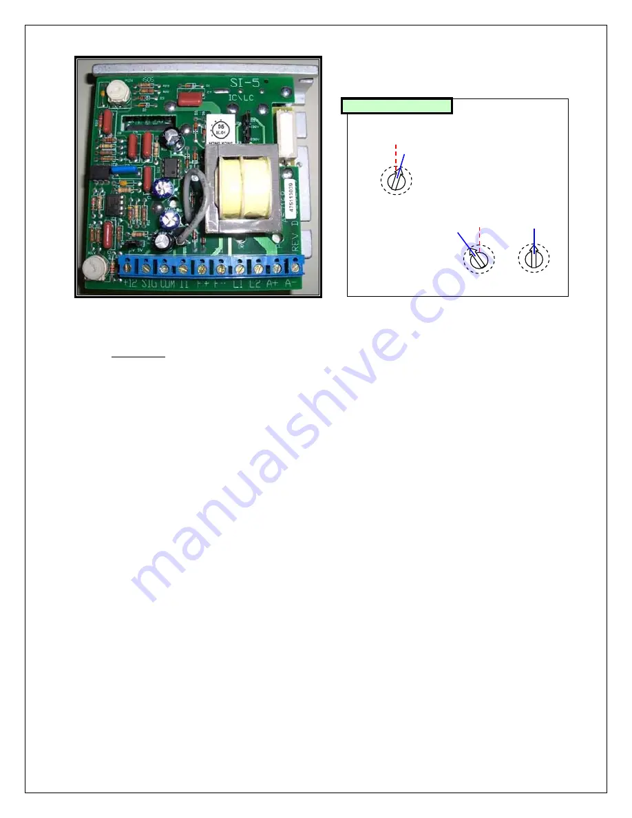
Figure 15
WARNING:
ELECTRICAL SHOCK HAZARD.
Extreme caution should be taken when working around live voltages. This adjustment
should only be performed by an experienced electrical engineer or technician.
I.
MIN Speed Adjustment.
A.
Adjust both the MAX and MIN trimpot to the maximum setting (Full clockwise) and adjust the CL
(current limit) trimpot to the middle of its adjustment range. (12 o’clock position)
B.
Set the Edge Hold Width to a sample board width. (Profile board, Edge Width board, etc…)
C.
Verify power to the controller by checking for 230VAC voltage across wires # 87 and 88 at the
terminals L1 and L2 on the controller.
D.
In the software application program, set the computer control speed setting to 0 cm/min. (0%
power)
E.
Observe the transport system and note any movement of the system.
F.
If the transport system is moving, slowly adjust the MIN trimpot counter-clockwise until the
transport system stops.
G.
In the software application program, set the computer control speed setting to 19 cm/min. (~10%
power)
H.
Observe the transport system and check for movement of the system.
I.
If the transport system is not moving, slowly adjust the MIN trimpot clockwise until the transport
system starts moving.
J.
Repeat the above steps as necessary.
II.
MAX Speed Adjustment.
This calibration should be done ONLY AFTER the MIN speed adjustment has been completed.
A.
In the software application program, set the belt speed set point to 188 cm/min. Adjust MAX
trimpot for PV = 188 and OP = 100% slowly. Adjust MAX trimpot clockwise (to increase speed or
decrease OP %) or counter-clockwise (to decrease speed or increase OP %) accordingly.
B.
Place the sample board on the EHC/Mesh Belt and using any reference mark, time the board
speed. Compare the calculated speed (distance/time) in cm/min. to the computer setting. (± 1.2
sec tolerance)
SI-5
KBIC/KBLC
ACCEL
(12)
1
IR
(12)
10
CL
12
BOTTOM LAYER
Summary of Contents for TCM-2200
Page 5: ...1 Introduction ...
Page 6: ...2 ...
Page 18: ...14 ...
Page 19: ...15 Facility Installation ...
Page 20: ...16 ...
Page 26: ...22 ...
Page 27: ...23 Operating System Software Guide ...
Page 28: ...24 ...
Page 55: ...51 ...
Page 56: ...52 ...
Page 57: ...53 ...
Page 58: ...54 ...
Page 64: ...60 ...
Page 65: ...61 Standard and Optional Equipment Operating Guide ...
Page 66: ...62 ...
Page 71: ...67 Troubleshooting Guide HC1 X or HC2 controller ...
Page 72: ...68 ...
Page 74: ...70 ...
Page 95: ...91 Figure 12 ...
Page 107: ...103 Maintenance Procedure ...
Page 108: ...104 ...
Page 110: ...106 ...


