background image

33 


2. Recipe 


Figure 17 


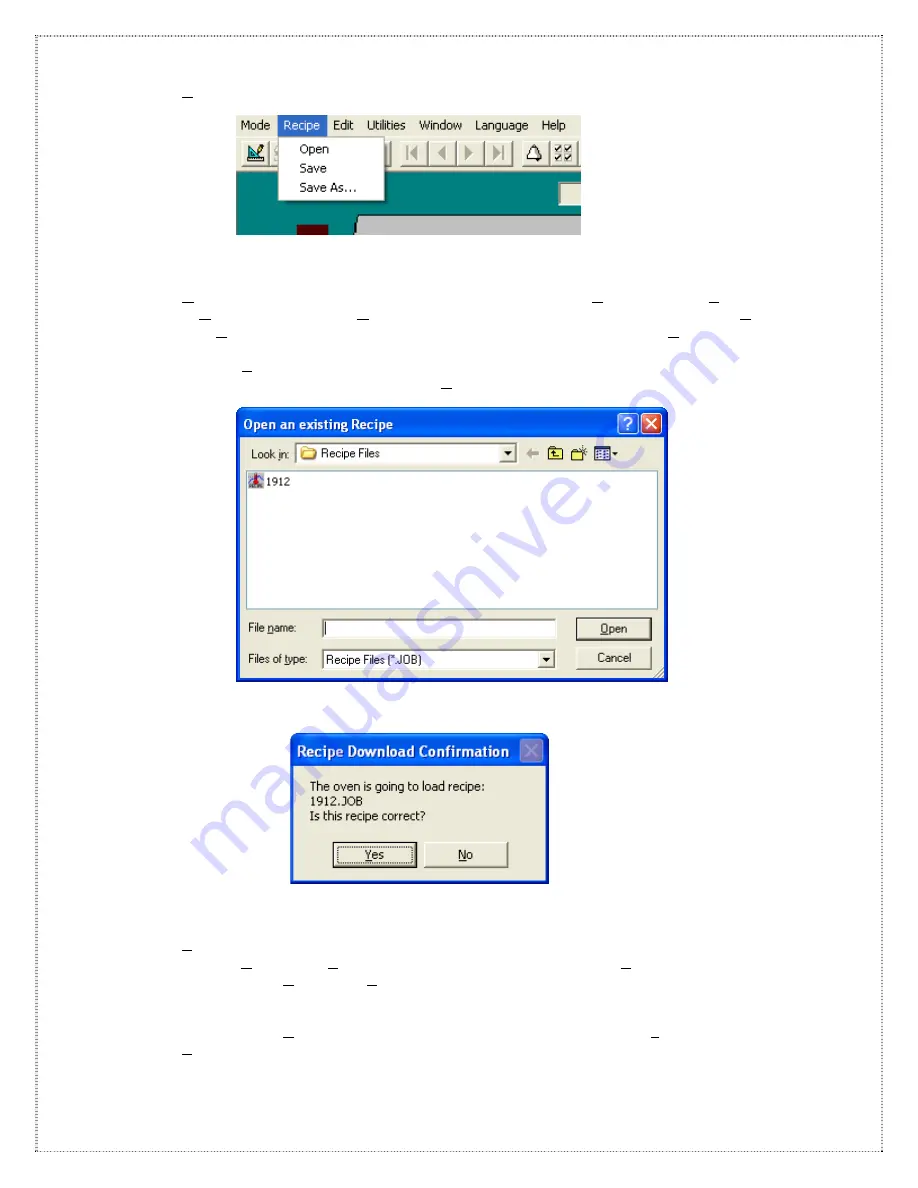
a. Open recipe will prompt to open an existing recipe only in the Operate mode or Edit mode. 

In Operate mode click the Open icon on the main toolbar or from the menu bar click Recipe 
then Open. Select desire recipe to operate or type recipe name and click Open (

See 

Figure 

18

). A prompt to ensure that the selected recipe confirmation will display (

See 

Figure 19

). 

Clicking ‘Yes’ will allow loading an existing recipe from the recipe menu. This recipe will now 
control and monitor the oven. Clicking ‘No’ will return to the recipe selection window screen.  


Figure 18 


Figure 19


b. Save recipe will save an active recipe under the same file name with no further prompting in 

both the Operate and Edit modes. From the main toolbar click the Save icon or from the 
menu bar click Recipe then Save. 


c.  Save As… recipe will save an active recipe under a new / different file name. From the 

menu bar click Recipe then save as… Type a new recipe name in File name: and click Save 
As or depress the Enter key (

See 

Figure 20

). 

Summary of Contents for TCM-2200

Page 1: ...Operation Manual Troubleshooting and Maintenance Guide for Oven Models TCM 2200 TCM 3300 TCM 4600 P N 7222937 Revision A ...

Page 2: ...e downloaded from Contact Us http www nordsonasymtek com Nordson ASYMTEK welcomes requests for information comments and inquiries about its products Please contact us using the information below Headquarters 2762 Loker Avenue West Carlsbad CA 92010 6603 USA Toll Free 1 800 ASYMTEK 1 800 279 6835 Tel 1 760 431 1919 Fax 1 760 431 2678 E mail info asymtek com Website www asymtek com Technical Support...

Page 3: ... Logging and Interval Time 44 G Channel Trend Plot Screen Setup 45 H New User Log On 46 I User Log Off 46 J Acknowledge Alarm 46 K Shutting Down the System 47 L Editing Parameters from the Channel Setup Screen 47 M Modifying A Recipe 48 N Loading A Recipe 48 O Deleting A Recipe 48 P Software Version 48 Q System Setup 49 Standard and Optional Equipment Operating Guide I Alarm and Warning Options an...

Page 4: ...or Speed Controller Adjustment 96 XI Conveyor Speed Not Stable 99 XII Machine In A Warning Condition 101 XIII Tripped Breakers 101 Maintenance Procedures Index 105 I Replacing A Top IR Panel 107 II Replacing A Bottom IR Panel Removing the Edge Hold Conveyor 108 III Adjusting the Slip Clutch Edge Hold Conveyor w o mesh belt 109 IV Replacing an SSR Solid State Relay 110 V Replacing A Thermocouple 11...

Page 5: ...1 Introduction ...

Page 6: ...2 ...

Page 7: ...or a detailed explanation of software operation please refer to the section entitled Operating System Software Guide The section entitled Standard and Optional Equipment Operating Guide explains each of the features and available standard options It includes operating instructions as well as schematics and diagrams To use the troubleshooting guide please refer to the contents to select the trouble...

Page 8: ...n and must comply with all appropriate electrical and safety codes See instruction manual Section III in Facility Installation for power supply requirements Failure to follow electrical codes or the use of under rated supply conductors may cause property damage and may subject the operator to hazardous voltages The exhaust ducting for the oven should be designed and installed by a qualified HVAC t...

Page 9: ...system Troubleshooting and Maintenance Please be aware that although many service routines can be performed easily extreme caution should be exercised when working with live electrical circuits ONLY a trained electrical technician or engineer should perform this work Before removing any panels all power to the oven should be switched off and the temperature should be at room ambient While system c...

Page 10: ...es them in detail Table II 1 Safety Hazard Labels Label Part Number Description 2545 Hazardous Voltage Warning Warns personnel of areas where high voltage is present which may cause severe injury or death 3628 Hot Surface Warning Warns personnel of hot surfaces that may cause burns if touched 3627 Moving Parts Warning Warns personnel to keep hands and fingers away from mechanisms that could cause ...

Page 11: ... qualified and authorized personnel should perform equipment installation setup maintenance troubleshooting and repair II 5 Electrical Hazards WARNING Always disconnect the equipment from the power source and attach a lockout device to the electrical disconnect before performing any maintenance or repair II 6 Fire Hazard WARNING Always use class c fire extinguisher in case of any fire in Asymtek C...

Page 12: ...enerated during system maintenance and servicing should be considered hazardous waste Consult with your facility safety officer and the manufacturer s Material Safety Data Sheet for instructions concerning proper disposal of hazardous materials Contact Asymtek if you have any questions CAUTION Customer should be aware that the flux they add to the oven will be exhausted Component Disposition Inter...

Page 13: ...tal engineers prior to system start up Contact Asymtek if you have any questions Hazardous Energy CAUTION Thermal Energy Oven may be HOT wait until oven cools down or proper insulated gloves should be used See Operating System Software Guide Section K CAUTION BBU Energy Oven BBU will be turned OFF remotely by rotary switch OFF position with one bip sound If BBU bip sounds more than once turn BBU O...

Page 14: ...mended Decommission Procedures Component Disposition Chamber Residue Discard in accordance with local safety environmental regulations Aluminum Parts Recycle aluminum Chamber panels shelves doors and hardware Steel Parts Recycle all steel parts Copper Wiring Recycle any copper wiring Electronic Components Discard in accordance with local safety environmental regulations Plastics Recycle or discard...

Page 15: ...ooldown mode This is accomplished via relay contacts that set the heater power contactor to the OFF state and stop system conveyor operation To reset E Stop function twist emergency stop button and press E Stop Reset oven stays in Cooldown mode To restore full power to the system heaters and system conveyor reset system software and load a wakeup or hot job recipe from the system software CAUTION ...

Page 16: ...ecovery information GREEN OK The system is ready to process material FLASHING YELLOW WARNING OR NEW JOB The System warning Board drop Board backup or Job start up II 10 1 Audible Alarm This option consists of an audible signal that sounds when the system goes into an alarm mode or board drop occurs The signal is activated whenever the red light on the light tower is illuminated In the event of an ...

Page 17: ... to the oven 5 Turn oven power OFF by rotating the main rotary power switch to the OFF 0 position a This will also remotely shut off BBU unit if equipped BBU unit will beep once during shutdown 6 Turn off supply power to the oven at facility three phase circuit breaker feeders 7 Obtain locks and tags from facility lock out tag out station 8 Lock out and tag out the following energy source disconne...

Page 18: ...14 ...

Page 19: ...15 Facility Installation ...

Page 20: ...16 ...

Page 21: ...e entrance end of the oven by plugging in the connector and installing four mounting screws To remove the oven from the skid it will be necessary to remove lag screws Remove panels to access lag screws from the bottom cross tube of frame See Figure 1 The oven may now be lifted from the skid with a min 3 6 Metric Ton 8000 pound capacity forklift and moved into position by means of the casters mount...

Page 22: ...shows the service conductor current capacity required for all Asymtek oven models Use branch over current device rated at amperes described in tables below Please refer to the serial tag on the machine and or warning labels near the main terminals for the correct machine voltage and current Caution Use a voltmeter to verify the proper voltage before connecting the machine Table 1A shows standard o...

Page 23: ...processing there is too much exhaust flow VI Leveling the Machine Use a Precision bubble level with each division equal to 0 0005 inch per 10 inches or 0 05 mm per meter or 10 seconds per division Before starting check the accuracy of your level Set it on the conveyor on the X axis and record the reading Then turn it 180o and the reading should be the same If it is not the level is out of calibrat...

Page 24: ...ower selector switch located behind the computer is set to 240V Plug the computer in to the outlet mounted to the machine frame Connect the oven communication cable 9 pin D connector to the COM1 for HC1 X controller and Use Ethernet port for HC2 controller at the rear of the computer If oven has another communication cable for dansensor or satellite KIC connect to COM2 port If oven has another two...

Page 25: ...onnections electrical or otherwise have been made according to the above instructions Ensure all packing material is removed Read the instruction manual X Sprinkler Fire Suppression System Special Precautions should be taken if the unit is installed in a sprinklered room or building Your Sprinkler contractor should be consulted to determine if the existing sprinkler system has properly rated sprin...

Page 26: ...22 ...

Page 27: ...23 Operating System Software Guide ...

Page 28: ...24 ...

Page 29: ... is familiar with the fundamentals of the Windows operating environment such as mouse operation toolbars and menus If the user requires more information please refer to the Windows system documentation A Starting the Program Turn the computer on Oven Operating Program will start automatically If not then double click on the Oven Operating Program Icon on the desktop as shown in Figure 1 Figure 1 T...

Page 30: ...the individual configuration of the oven many different parameters and controls will be displayed This is the central screen view of the program and will appear after logging on and a recipe has been loaded The Main Overview Screen also serves as the recipe editor See Figure 4 Note the green status bar at the bottom left of Figure 4 with the message Communicating with Hc2 This applies only to oven...

Page 31: ...ed through the oven by displaying animation of the board as it passes under the incoming board sensor if equipped 8 The supply of nitrogen to the machine can be turned on or off by clicking on the toggle switch labeled nitrogen on the overview screen 9 The board drop option will allow the detection of a board falling off the edge hold conveyor during the cure process and to establish a warning sig...

Page 32: ...are Timer Key may be used between computer and HC1controller The software will continually monitor and control all digital I O as well as all the temperature and conveyor rail channels From the main toolbar click the Operate icon or from the menu bar Mode then select Operate You will then be prompted to open an existing file See Figure 8 To open an existing file single click on a recipe click Open...

Page 33: ...n mode overview screen From the main toolbar click the Operate icon or from the menu bar click Mode then Operate Follow the procedure for loading a recipe as outlined in section 1 a See Figure 8 c Edit mode will allow the operator to generate or change recipes off line or while the oven is being controlled by another recipe Click on the main toolbar Edit icon or the menu bar Mode then Edit you wil...

Page 34: ... off the power to the heaters and leaving the conveyor and blowers operating until all the temperature channels are below 95 degrees centigrade From the main toolbar click the Shutdown Exit icon or from the menu bar Mode then Shutdown Exit confirm to load Cooldown See Figure 11 After clicking Yes Cooldown will be loaded Figure 11 The program will remain in the overview screen in Cooldown mode See ...

Page 35: ...down Mode then by clicking the Shutdown Exit icon on the main toolbar or from the menu bar Mode then Shutdown Exit will terminate the Oven Operating Program e Exit without shutdown will exit the application program without any affects on last loaded oven recipe From the main toolbar click the Exit without shutdown and after clicking Yes to Figure 13 below application program will be shutdown with ...

Page 36: ...ill be existing running recipe through controller Figure 15 By clicking Yes user will be prompted for a new recipe which will overwrite the current recipe stored and running on the controller Upon selection of recipe user will be asked for Recipe Download Confirmation See Figure 16 Clicking Yes will load selected recipe Figure 16 ...

Page 37: ...oading an existing recipe from the recipe menu This recipe will now control and monitor the oven Clicking No will return to the recipe selection window screen Figure 18 Figure 19 b Save recipe will save an active recipe under the same file name with no further prompting in both the Operate and Edit modes From the main toolbar click the Save icon or from the menu bar click Recipe then Save c Save A...

Page 38: ...he Ack All icon on the main toolbar d Clear Alarms will erase all acknowledged alarms listed in the alarm log window From the menu bar click Edit then Clear Alarms or click the Clear Alarms icon on the main toolbar Note Some alarm related sub menus are active only in Alarm window e Silence Alarms will allow turning off the audible alarm if it is on If some other alarm condition occurs audible alar...

Page 39: ...at allows the user to generate an automatic recipe or Cooldown start event Click the Calendar icon on the main toolbar or from the menu bar click Utilities then Calendar See Figure 24 See section D Scheduling Calendar Events in this section for how to setup calendar to schedule events ...

Page 40: ...h the proper password to enter edit or delete users and their accessible functions Click the Security icon on the main toolbar or from the menu bar click Utilities then Security See Figure 25 See section E Setting up user security in this section for setting up user security Figure 25 ...

Page 41: ... to enter specific colors line styles and channel variables to the channel plot views Click the Trend Plot Setup icon on the main toolbar or from the menu bar click Utilities then Trend Plot Setup See Figure 26 Figure 26 e Log On displays the new user log on screen that allows users to change to a different user name and password This user will gain access to the functions available to his her ass...

Page 42: ... recipe Select the recipe file and click Open or depress the Enter key Select the print icon from the menu toolbar Note The user cannot print current open recipe in the Operate Mode h Print Journal will print all the events which have occurred on the oven From the menu bar click Utilities then Print Journal Select the Journal file and click Open or depress the Enter key Select the print icon from ...

Page 43: ...iew icon on the main toolbar or from the menu bar click Window then Main Overview See Figure 30 Figure 30 b Channel Setup Screens display all the data for the individual channels It also serves to allow the user to enter control and alarm setup parameters Click the Channel Setup icon on the main toolbar or from the menu bar click Window then Channel Setup See Figure 31 Figure 31 ...

Page 44: ...el Trend Plot See Figure 32 Figure 32 d Alarm Screen displays a list of alarms and warnings that have occurred Next to each alarm or warning there are check boxes for acknowledgement Click the Alarm icon on the main toolbar or from the menu bar click Window then Alarm See Figure 33 Figure 33 e Events Screen displays the information stored in the daily journal file Every keystroke alarm warning and...

Page 45: ...guage Figure 35 The language selection drop down menu will allow the user to select other languages like English German Japanese Korean and Spanish Languages other than English may not display correctly if proper language fonts are not enabled in windows operating system By default software is setup for English language ...

Page 46: ...p or down arrows to the desired minute At the end set AM or PM by clicking the down arrow at the AM PM box 3 Select the desired Recipe by either clicking From File or defaulting to Cooldown If a recipe other than Cooldown needs to be scheduled click on Browse for a listing of available recipes Double click on a Recipe name in the dialog box click on a Recipe name then depress the Enter key or clic...

Page 47: ...the Enter key A prompt will appear to confirm the addition of this new user to the list Click Yes or No Figure 38 Finally you must re enter the password to confirm the entry onto the user list Figure 39 Repeat the above steps until all of the users of the oven are defined Changes to a user password can be accomplished by clicking on the user name then clicking the Edit button and ...

Page 48: ...tab to assign functions to the user groups To assign accessible software functions to the user status group click on the defined function then click the OPERATOR ENGINEER or SUPERVISOR button The function will appear in the status window Functions can be removed from status groups by first clicking on the function in the status window then click the REMOVE button for the associated window The func...

Page 49: ...y contain a separate plot for up to five process variables and corresponding output percentages One Process Variable is always enabled by default To edit or add more plots click on the Enable Plot check box then click on the PVColor or OPColor buttons A screen with different color boxes will be displayed Click on the desired color box then click the OK button Next to insert a line style click on t...

Page 50: ...the logoff icon and click Yes This will disable access to all Oven Operating Program operations Only Log On icon is accessible Figure 44 J Acknowledge Alarms Figure 45 If an alarm should occur on the oven a box explaining the type of alarm will be displayed over the screen that is presently in use The user must acknowledge these messages The oven will go into the Cooldown mode before the Alarm Scr...

Page 51: ...ar click Mode then Shutdown Exit to return to the desktop From the desktop screen the user can shutdown the computer before removing power to the oven L Editing Parameters from the Channel Setup Screen It is not recommended that the channel parameters other than the Set point be changed without first consulting with the factory service department Making changes may cause abnormal machine operation...

Page 52: ...cipes can be modified in operate or edit mode While in operate mode the oven will respond to set point changes and if the user is satisfied with the results can click the Save icon on the main toolbar or from the menu bar click Recipe then Save New recipes can be created in operate or edit mode Change the set points as required for the new recipe click on Recipe Save As type new name and save the ...

Page 53: ...None TCM 3300 10 Zones 1900 Left to Right Channel 23 24 25 26 None TCM 3300 10 Zones 1900 Right to Left Channel 1 2 3 4 None TCM 4600 13 Zones 1900 None Channel 13 56 Page 2 defines the options of the oven and their associated parameters Check boxes enable the options in software and edit boxes allow for the parameters to be set Page 3 defines the blower control option and alarm setup parameters P...

Page 54: ...be prompted on finish button By selecting Save Setup And Exit user will be exit with changes made and by selecting Do Not Save And Exit user will be exit without any changes to setup wizard See Oven System Setup Wizard Pages 1 to 7 ...

Page 55: ...51 ...

Page 56: ...52 ...

Page 57: ...53 ...

Page 58: ...54 ...

Page 59: ...ror File Path ________________________ 15 IO Logging Days HC1 Ctrl Assumes continuously running oven Default Language ________________ Page 2 Options Center Board Support Up Down Nitrogen Computer Ctrl N2 Auto Purge Standby CBS Up Down Feedback Second Center Board Support Up Down Password Protect Nitrogen Button Dansensor Settings Purge Time ______ min Normal Time ______ min Second CBS Up Down Fee...

Page 60: ...________ Type __________ Delay ______ sec Audible Buzzer Dansensor Settings Single Channel Monitor Multi Channel Monitor Disable Dansensor Closed Loop with Standby control PPM Level Normal _____ PPM Level Standby _______ Release Autopurge Standby Digital Outputs Alarm2 Selection Alarm2 High Alarm2 Low Alarm1 Alarm1 Level Normal _____ Alarm1 Level Standby ______ Note for Closed loop with Standby co...

Page 61: ...il Width Control Type Automatic Coast Offset ____cm Home IN Coast Offset ____cm Home IN Backup Dist ____cm Hunt as Home IN Backup Dist ____cm Hunt as Home IN Home Dist _____cm Travel Dist _____Min ______Max Pulse per cm 1576 Tolerance _____ _____ cm Maximum Retry _____ Home Dist _____cm Travel Dist _____Min ______Max Pulse per cm 1576 Tolerance _____ _____ cm Maximum Retry _____ Manual Hardware Ra...

Page 62: ...ut range low 0 cm min or in min Max Frequency ______ Hz Max Frequency ______ Hz Warning Delay Time _____ sec Warning Delay Time _____ sec Deadband Dev Time _____ sec Deadband Dev Time _____ sec Open Loop for 1088 Maximum output 100 100 cm min Minimum output 0 0 cm min Board Tracking option Audible Board Warning Smema Lane 3 Audible Board Warning Smema Lane 4 Board processed Animation Lane 3 Board ...

Page 63: ...ON OFF Heat 8 9 ON OFF Heat 9 10 ON OFF Heat 10 11 ON OFF Heat 11 12 ON OFF Heat 12 13 ON OFF Cool 1 Flux Heater 14 ON OFF Belt 1 Speed 15 ON OFF Heat 15 16 ON OFF Heat 16 17 ON OFF Heat 17 18 ON OFF Heat 18 19 ON OFF Heat 19 20 ON OFF Heat 20 21 ON OFF Heat 21 22 ON OFF Heat 22 23 ON OFF Heat 23 24 ON OFF Heat 24 25 ON OFF Heat 25 26 ON OFF Heat 26 27 ON OFF Profile 1 28 ON OFF Profile 2 29 ON OF...

Page 64: ...60 ...

Page 65: ...61 Standard and Optional Equipment Operating Guide ...

Page 66: ...62 ...

Page 67: ...an optional Light Tower Configuration LTO This is enabled via the Oven Setup wizard under miscellaneous options STATUS COLOR Reasons OK No Light or Green Light Ready New Job Flashing Green Job Start up Alarm Flashing Red Alarm Board Drop Board Backup Warning Flashing Yellow Warning Table 2 Only one light tower output will be set at any time When the Oven Operating Program is terminated all light t...

Page 68: ...on of the device III Edge Hold Conveyor System and Options A Description and Standard Operation Each Asymtek oven model can be equipped with either a single conveyor or a dual conveyor system Each conveyor system has one fixed position rail and one adjustable rail The adjustable rail can be moved to position by means of its power drive or optional computer control The control for the power width a...

Page 69: ...o the desired position by means of a lead screw This lead screw is powered by its own motor and is separate from the motor lead screw that adjusts the position of the edge hold rail The controls for adjusting the centerboard support are located next to the controls for the edge hold rails To adjust the location of computer controlled centerboard support go to main overview screen The window RAIL 1...

Page 70: ...tive action A board stop alarm or warning will be triggered by boards that do not clear the oven exit sensor Board Count This option allows the computer to display a count of the number of boards processed by the oven since a particular recipe has been loaded As a board enters the oven it activates a sensor at the entrance counting a board in As the board leaves the oven it activates a sensor at t...

Page 71: ...67 Troubleshooting Guide HC1 X or HC2 controller ...

Page 72: ...68 ...

Page 73: ...reaching temperature 80 High deviation of a heat zone or a zone overheating 83 High process alarm 86 Zone temperature is not stable 89 Heat rise rate alarm 92 Software Lock Up or Odd Behavior 93 Conveyor Not Moving 93 Conveyor Speed Controller Adjustment 96 Conveyor Speed Not Stable 99 Machine in a Warning Condition 101 Tripped Breakers 101 ...

Page 74: ...70 ...

Page 75: ...coming supply lines to the oven and verify they are supplying the required voltage as marked on the serial tag Using a multi meter set to measure AC volts probe the main switch terminals L1 L2 and L3 Each combination L1 L2 L2 L3 and L1 L3 should be verified If the correct voltage is not found on one or more phases there is a problem with the power supply in the facility ...

Page 76: ...54 wires on the transformer secondary See Figure 2 A lack of voltage could indicate a faulty transformer that should be replaced For low voltage machines verify power between circuit breakers Q27 and Q28 It should be 208 240V Note If machine is 208 240V no transformer is required 3 Check for tripped circuit breakers Q27 and Q28 located on the upper row of circuit breaker s on the left side of the ...

Page 77: ...o the base of the oven Verify that the cable with the 9 pin D connector is plugged into the battery backup unit Battery backup turns ON and OFF with main rotary switch located at front of the oven Figure 3 2 The battery backup unit may be removed from the oven if necessary to test It may be bypassed by unplugging the line cord and power cord from the rear of the unit and connecting the line cord w...

Page 78: ...hould be 240 VAC For low voltage machines voltage should be 208 240V 3 Check for tripped breaker Q31 located at left end of electrical panel 4 Check the computer itself by plugging it into another outlet Computer will work on 120V or 240V Note Set the power selector switch located on backside of the computer for the applicable voltage ...

Page 79: ...re fuses F1 F2 0 25A are not open See Figure 4a 4 Check the proper connection of communication cable and also check wiring for communication cable Communication cable should be connected at J13 For HC2 Control board 1 Check the power input between the terminals marked J1 and J1 It should be approximately 24VDC See Figure 4b 2 Make sure fuse F1 1A is not open See Figure 4b 3 Check the communication...

Page 80: ...l Board Jumper JP12 need to set for proper frequency to match with main 3 phase oven power frequency 60Hz do not install jumper JP12 50Hz install jumper JP12 Warning Do not install or uninstall jumpers on controller while it is powered on ...

Page 81: ...g is not conflicting with the other devices such as modem networks card etc For HC2 Control board 1 Other program connected at com ports will not affect HC2 communication because HC2 uses Ethernet port 2 Default IP address of HC2 board is 192 168 10 250 3 Setting up computer IP address 192 168 10 1 Last digit will be any number except 250 If computer IP address is not set properly or network cable...

Page 82: ...78 Select Internet Protocol TCP IP and then click on Properties button Set IP address and subnet mask as below Click OK to save changes Restart the computer ...

Page 83: ...rk card COM card etc are not conflicting with the address or interrupts used by COM1 3 Verify that the computer COM1 port is functioning Use an RS 232 port tester to test for activity on transmit data line pin 3 Or change the computer if a replacement is available For HC2 Control board 1 For HC2 control board verify that the communication Ethernet cable is connected to J1 jack at board to the comp...

Page 84: ...estion using arrow key A typical channel setup screen for a heat zone is shown in figure 5 Figure 5 2 Verify that the alarm deviation is set to at least 40 degrees C The deviation is factory set to 40 o C 3 Verify that the control output is set in AUTO mode The software should automatically set the power output to 100 4 Verify that the TI value should be set to 500 for IR panel heaters ...

Page 85: ...located in the center of the contactor or along the right side See Figure 6 Figure 6 Check for tripped breaker for the heat zone in question Reset if necessary and reload jobs The heater wiring and elements should be checked next Set the meter to the ohms scale With the main power off measure across the heater coils for the suspected zone example for heat zone 1 L R wires 1 and 2 etc See Figure 7 ...

Page 86: ...and load a recipe Set the output power percentage to manual 100 Using a voltmeter set to VDC scale check the input control voltage on the SSR for the non heating zone with the common lead to terminal 4 and the v lead on terminal 3 ...

Page 87: ...chine probe terminals 1 and 2 If voltage reading is equal to machine input voltage the SSR is not conducting and should be replaced See Maintenance Procedures If no voltage is read on the meter the SSR is functioning properly 2 Verify that the blower motor for the suspect zone is functioning If it is not see Troubleshooting Guide section X See also Troubleshooting Guide section VI IV Computer repo...

Page 88: ...r value follow the Thermodynamics and Hardware sections explained below 8 Verify that the TI value should be set to 500 for IR panels heaters B Thermodynamics 1 If the set point of adjacent zones differs by more than about 30 degrees C the other zone may in fact heat the zone with the lower set point thus causing an over temperature condition This condition may be corrected by adjusting the set po...

Page 89: ...ire and ground Continuity indicates a shorted heater coil or frayed wire which should be replaced See Maintenance Procedures section I 3 Using a voltmeter set to VDC scale check the input control voltage on the SSR for the over heating zone with the common lead to terminal 4 and the v lead on terminal 3 Note you must be running a recipe and set the zone in question to manual 0 power If the DC volt...

Page 90: ...ing and is functioning normally If no voltage is read on the meter the SSR is faulty and should be replaced by following the procedure in the maintenance section See also Troubleshooting Guide section VI V Computer reports a High process alarm Check For A Software 1 Load the same recipe that was running at the time this alarm occurred see software section 2 Choose Channel setup from the Window men...

Page 91: ...ng Guide section IV B Controller 1 If the process value PV reads 3277 in all zones then reset the thermocouple module Thermocouple Module To reset the thermocouple module turn OFF the main power of the oven using the rotary switch located at front side of oven for about 10 to 15 seconds and then turn the power back ON If the problem persists thermocouple module may not be making a good contact wit...

Page 92: ...y that the thermocouple for the zone in question is not open by performing the following steps Note If the controller checked out in step B the computer will read 3277 if the thermocouple is open Visually check for proper connections at the thermocouple blocks and controller If all connections are visually OK disconnect the thermocouple from the HC1 X or HC2 controller and test with an ohmmeter Yo...

Page 93: ...the plot to show the set point output and process variable for the zone in question See Operating System Software Guide section C 4d Then choose Channel Trend Plot from Window menu A typical trend plot is shown in figure 10 Figure 10 2 Examine the plots on the screen If the PV Process Value curve is very erratic as shown in figure 11 suspect a faulty thermocouple that is shorted to earth ground Ve...

Page 94: ...rve oscillates by more that about 20 or is erratic suspect a faulty SSR Provided the thermocouple was OK See step 2 If the trend plot resembles Figure 12 replace the SSR Solid State Relay for the suspected zone See Maintenance Procedure section ...

Page 95: ...91 Figure 12 ...

Page 96: ...e is shorted outside of the heater module it will not read the temperature of the zone but instead a temperature outside of the oven 2 Open the oven and run the Wakeup recipe See Operating System Software Guide section Change the set point of the suspect zone to 50 degrees Verify that the zone is actually heating If it is not then see Troubleshooting Guide section III 3 Visually check for shorts a...

Page 97: ...ications like KIC to see if that has an effect 4 If problem still persists contact factory for service IX The conveyor is not moving Check For A Emergency stop pressed Verify that an emergency stop has not been pressed Also be sure to press the blue E Stop reset button if installed B Setpoint 1 Verify that the setpoint for the conveyor speed is not set to zero See main Over View screen 2 Choose Ch...

Page 98: ... power leads removed from the motor check for continuity between the motor leads and earth ground using the multimeter set to the ohm scale Continuity indicated that the motor should be replaced Also check the resistance of the motor windings If there is a short or open circuit replace the motor 4 Check carbon brushes after every 2000 hours of operation If the length of either brush is 3 16 4 8mm ...

Page 99: ...r lubrication of sprockets or chain may cause gumming If lubrication has gotten into the oilite bronze bearings in the sprockets the sprockets should be removed and cleaned b Worn sprockets bearings or shoulder screws Sprocket with worn or broken teeth or worn bearings or shoulder screws should be replaced c See section IV in Operating Guide section for overload current limits settings for the mot...

Page 100: ... the calibration of the oven EHC Mesh belt transport system motor controller located on the electrical panel CP 4491 The calibration procedure should be performed after the oven has been powered and computer control of the EHC mesh belt transport system has been established The calibration should be performed in the following order 1 MIN speed trimpot adjustments 2 MAX speed trimpot adjustments 3 ...

Page 101: ...slowly adjust the MIN trimpot counter clockwise until the transport system stops G In the software application program set the computer control speed setting to 19 cm min 10 power H Observe the transport system and check for movement of the system I If the transport system is not moving slowly adjust the MIN trimpot clockwise until the transport system starts moving J Repeat the above steps as nec...

Page 102: ...d adjustments have been completed The desired threshold for the transport is 30 to 40 in lbs of force This is the force required to cause the transport motor controller to stop current limit the conveyor A Tools required 10 100 inch pound 3 8 drive torque wrench set to 40 inch pounds 5 8 open end and 3 8 drive crow s foot wrench B In the software application program set the computer control speed ...

Page 103: ...fy that the setscrews on the encoder are tight 3 Be sure the wiring to the encoder is securely attached to both ends at the encoder and at the connection to the HC1 X or HC2 controller 4 Check carbon brushes after every 2000 hours of operation If the length of either brush is 3 16 4 8mm or less replace both brushes with the same grade of material See maintenance section for inspection replace proc...

Page 104: ...e TPO PB 0 Action REVERSE TI 150 TD 0 DF 3 Alarms Control AUTO 1 Check the values for Belt Speed Control in Oven System Setup Wizard page 5 See section System Setup in Operating System Software Guide section for adjusting these values ...

Page 105: ...ps breakers Check For A Heater breakers Heater or wiring may have shorted to ground See Troubleshooting Guide sections III and IV B Q26 C Q27 D Q28 E Q29 F Q30 For High Voltage Ovens only Check oven transformer T1 Check all blower motors and muffin fans for operation one by one Check hood lift circuit and Battery Backup if installed input The 24 VDC power supply may be faulty and should be replace...

Page 106: ...102 G Q31 The computer outlet is fused for 6 Amps to operate the computer and monitor only Do not run any other equipment from this outlet ...

Page 107: ...103 Maintenance Procedure ...

Page 108: ...104 ...

Page 109: ...old Conveyor 108 III Adjusting the Slip Clutch Edge Hold Conveyor w o mesh belt 109 IV Replacing an SSR Solid State Relay 110 V Replacing A Thermocouple 111 VI Replacing DC motor carbon brush 112 VII Lubrication 113 VIII Verifying Accuracy of the System 114 IX Profiling 116 X PM Schedule 119 ...

Page 110: ...106 ...

Page 111: ...e position Also make sure heater wire connections with color code to position shown below in picture 3 Replace new IR module and connect heater wires Insert thermocouple wire about 11 43 cm inside the IR module through thermocouple tube and use hi temp tape around thermocouple wire at wire fitting Inspect thermocouple wire before installing in new IR module Inspect the condition of the heater wire...

Page 112: ...ve sprockets 6 Pull the chain all the way out of the rail Repeat for each rail 7 Remove the socket head screws from the long section of rail Watch for shims 8 Pull the rails out toward you firmly The rails will slide from a steel expansion block which connects them to the shorter set of rails 9 Repeat the same procedure for replacing a top IR panel 10 When sliding the rail back in place and over t...

Page 113: ...uare shaft Install the crow s foot onto the torque wrench Test fit the 5 8 open end of the crow s foot onto the square shaft It should be easily installed and removed Check for enough clearance to sweep the wrench from vertical to horizontal 12 00 to 3 00 position w o hitting any down stream equipment or obstructions Power up the oven Load the wakeup job Set the belt speed to 90 cm min in software...

Page 114: ...efer to lockout tagout procedure in Introduction Safety Precautions Section II 11 2 Locate the Oven SSR Board Warning Use appropriate Power Lockout Procedures for Safety 3 Remove plastic cover by removing the four button head screws Torque Wrench Crows Foot Wrench ...

Page 115: ...s or see Maintenance Procedure section II for accessing lower thermocouples 2 Refer lockout tagout procedure in Introduction Safety Precautions Section II 11 3 To remove thermocouple from IR module see section I for top IR module and section II for bottom IR module 4 Disconnect the thermocouple from the terminal block located with heater terminal block 5 The thermocouple is held in place with RTV ...

Page 116: ...lastic cap with a flat head screw driver and open each carbon brush 5 If the length of either brush is 3 16 4 8mm or less replace both brushes with the same grade of material These brushes should be ordered from the factory Please keep motor name plate information handy before contact the factory 6 Insert new or same brush back and tight the plastic cap over it 7 Install motor back to the oven Bef...

Page 117: ...32 ISO VG 220 oil used on Edge Hold chain The chain used for the edge hold conveyors on Asymtek systems is made of stainless steel and does not require lubrication There is however friction between the chain and the channel in the edge holds rails This is where the lubrication is required With no boards in the oven load Wakeup By using the supplied brush dab a small amount of lubricant on each cha...

Page 118: ...d acceptable for the Asymtek Oven at room temperature B Verifying Accuracy of the Temperature Controller The accuracy of the thermocouple inputs for the temperature control module in the Asymtek oven may be checked by using any NIST certified digital calibrator thermometer to simulate the operating temperatures of the sensor Asymtek recommends an OMEGA Model CL23A Asymtek part 4350 for this proced...

Page 119: ... is out of range by more than 3 0 C contact the factory so arrangements can be made to have the controller calibrated C Verifying Calibration of Belt Speed Belt speed channel of the HC1 X controller is the channel dedicated to the control of the belt speed It may be calibrated easily Choose Channel setup from Window menu select Belt speed channel Adjust the set point of the belt to 60 cm minute Us...

Page 120: ...sible when attaching thermocouples to component and board to minimize change to local thermal mass that can affect the accuracy and response time of the thermocouple Tape the thermocouples to the board to avoid stress at the joints during handling and dress the thermocouple wires into a neat pigtail to prevent tangling in the conveyor belt Place the board on the conveyor and fasten it in place wit...

Page 121: ... the maximum differential between the highest and lowest temperature on the circuit board should be less than 20 C the hottest spot should be less than 40 C above the solder melting temperature and the lowest temperature should be greater than 15 C above the solder melting temperature In general it is possible to set up one generic profile and vary the belt speed to obtain acceptable results with ...

Page 122: ...ating rates An excessive amount or old solder paste and excessive temperature ramp up rates promote solder balling Cure time should range from 30 seconds to 90 seconds Use a fine gauge K type thermocouple wire with high temperature insulation for all profiling We recommend GG K 36 WIRE Purchase from OMEGA ENGINEERING INC P O BOX 4047 STAMFORD CT 06907 0047 203 359 1660 K type thermocouples with pr...

Page 123: ...f the machine with Fantastic or 409 cleaner or equivalent For more than 800 C environment use high temperature lube Krytox XHT BDZ 3 Month Intervals Procedure OEM Manual References if any Check DC Motor carbon brushes after every 2000 hours of operation Conveyor drive Edge width motor Replace both brushes if the length of either brush is 3 16 4 8mm or less 6 Month Intervals Procedure OEM Manual Re...

Page 124: ...e Shipping When ordering spare parts specify which carriers you prefer to use and freight collect account number If no instructions are received Asymtek will determine the best shipping method and ship prepay add Warranty Contact Asymtek Technical Support for any warranty issues and to request a Return Material Approval RMA to return any warranty item NOTE Find your local Technical Support contact...

Page 125: ...MC standards EN 50082 2 1995 for immunity and EN 55011 Group 1 Class A for emissions Basic concepts general principles for design Part 1 EN ISO 12100 1 2003 Basic concepts general principles for design Part 2 EN ISO 12100 2 2003 Safety of machinery EN 954 1 1996 Safety of machinery EN 983 1996 In addition aforementioned complies with safety standard EN 563 1994 A1 1999 that sets allowable standard...

Reviews: