31
www.climacoolcorp.com
Space and Location Requirements
The most important consideration which must be taken
into account when deciding upon the location of air
cooled equipment is the provision for a supply of ambient
air to the condenser, and removal of heated air from the
condenser area . Where this essential requirement is not
adhered to, it will result in higher head pressures, which
cause poor operation and possible eventual failure of
equipment . Units must not be located in the vicinity of
steam, hot air or fume exhausts .
Another key consideration is that the unit should be
mounted away from noise sensitive spaced and must
have adequate support to avoid vibration and noise
transmission into the building . Units should be mounted
over corridors, utility areas, restrooms and other auxiliary
areas where high levels of sound are not an important
factor . Sound and structural consultants should be
retained for recommendations .
Consideration should also be made to make sure there is
sufficient space for removal/replacement of micro-channel
coils (when supplied) . A minimum of one unit width should
be allowed on the header end of the unit to provide
sufficient clearance.
Walls or Obstructions
The unit should be located so that air may circulate freely
and not be recirculated. For proper air flow and access, all
sides of the unit should be a minimum of “W”* away from
any wall or obstruction . It is preferred that this distance
be increased whenever possible . Care should be taken to
see that ample room is left for maintenance work through
access doors and panels . Overhead obstructions are not
permitted . When the unit is in an area where it is enclosed
by three walls, the unit must be installed as indicated .
Figure 19 - Clearance from Walls or Obstructions
Air Flow
W
W
MIN .
*W = Total width of the condenser
Remote Condenser
Multiple Units
For units side by side, the minimum distance between units
is the width of the largest unit . If units are placed end to
end, the minimum distance between units is 4 feet .
Figure 20 - Clearance for Multiple Units Placed Side by Side
Air Flow
Air Flow
W
MIN .
W
W
Units in Pits
The top of the unit should be level with the top of the pit,
and side distance increased to “2W” .
If the top of the unit is not level with the top of the pit,
discharge cones or stacks must be used to raise discharge
air to the top of the pit . This is a minimum requirement .
Figure 21 - Clearance for Units in Pits
Air Flow
10 FT . MAX
Stack
Supplied by Others
2W
MIN .
2W
W
MIN .
Decorative Fences
Fences must have 50% free area, with 1 foot undercut, a
“W” minimum clearance, and must not exceed the top of
the unit . If these requirements are not met, unit must be
installed as indicated for “Units in pits” .
Figure 22 - Clearance for Fence Enclosures
W
MIN .
W
MIN .
W
Air Flow
Clearance for Fence Enclosures
1 FT . MIN
Summary of Contents for CLIMACOOL UCR 30
Page 19: ...17 www climacoolcorp com Voltage Phase Monitor Wiring Diagram...
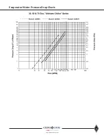
Page 29: ...27 www climacoolcorp com Evaporator Water Pressure Drop Charts...
Page 30: ...28 www climacoolcorp com Glycol Performance Adjustments Factor Charts...
Page 78: ...76 www climacoolcorp com Wiring Diagram...
Page 79: ...77 www climacoolcorp com Wiring Diagram...
Page 80: ...78 www climacoolcorp com Wiring Diagram CoolLogic Control Panel...
Page 81: ...79 www climacoolcorp com Wiring Diagram CoolLogic Control Panel...


