68
www.climacoolcorp.com
Stainless Steel Strainer Option
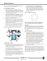
What is Water Hammer?
Water hammer is a phenomenon that can occur in fluid
systems with long pipes . Water hammer is a rapid change
of pressure caused by a rapid change in velocity. If the flow
has been abruptly shut off downstream, the pressure in the
entire system is raised very quickly .
What Causes Water Hammer?
Any action that can cause a rapid change in the velocity
of the flow can set off a water hammer, such as closing a
downstream valve, pump stoppage, etc . Typically, for short
lengths of pipe (below 500 feet) downstream valves that are
closed within 1/10 of a second can generate water hammer .
What Can Water Hammer Do?
Pressure spikes from water hammer can raise fluid pressures
to dangerously high values . These pressure spikes can cause
serious damage to valves, pipes, strainers, joints, etc . The
CS strainer is rated to an absolute maximum pressure of 150
psi for bolted lid models, and 125 psi for clamped lid models .
A water hammer pressure spike that raises the pressure
higher than the maximum rated pressure may result in
strainer damage, voiding the manufacturer’s warranty .
What Can I Do to Prevent Water Hammer?
There are certain precautions that can be taken to prevent
or decrease the effect of water hammer. The addition of a
surge tank or accumulator fitted with a suitable pressure
relief valve strategically located within the water system
may provide adequate protection against the effects from
water hammer . Careful attention should be given to the
design and control strategy for valves and pumps so the
actions do not invite a water hammer .
Stainless Steel Strainer Options
Automatic Timer Flush (ATF) Package Option
The ATF-EA-1.5 flush valve package provides an automatic
method for flushing away the debris collected in the strainer’s
reservoir . The power supply and timer controls for the valve
package are housed inside the ATF control box . The ATF
controls can be pre-programmed to set the flushing duration
and the time interval between flushes.
System Components
1 .
Timer based valve controller: (see Figure 29) sets the
flush duration (length of the flush) and the flush interval
(time between flushes).
2 .
Electric ball valve: designed for dirty water use (see
Figures 30 and 31) .
Figure 29
A
GREEN POINTER
INNER RING
(LENGTH OF FLUSH)
(FACTORY SET AT
8-SECONDS)
RED POINTER
OUTER RING
(TIME BETWEEN
FLUSHES)
(FACTORY SET AT
24-HOURS)
Figure 30
B
[email protected] POWER
FROM PDA OR 120V PLUG
IN TRANSFORMER
OPEN/CLOSE
INDICATOR
COVER-PLATE SCREWS
(4) IN CORNERS OF BOX
(TIMER BASED VALVE
CONTROLLER)
CONTROL SWITCH
Figure 31
Valve Specifications
A . Water-resistant polypropylene motor case
B . High torque motors with perma-lube gears
C . Open and close indicator
D . Stainless steel ball valve and hardware
E . Auto reset circuit breaker
F . 90° bi-directional rotation
G . Controller case
Summary of Contents for CLIMACOOL UCR 30
Page 19: ...17 www climacoolcorp com Voltage Phase Monitor Wiring Diagram...
Page 29: ...27 www climacoolcorp com Evaporator Water Pressure Drop Charts...
Page 30: ...28 www climacoolcorp com Glycol Performance Adjustments Factor Charts...
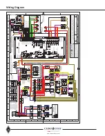
Page 78: ...76 www climacoolcorp com Wiring Diagram...
Page 79: ...77 www climacoolcorp com Wiring Diagram...
Page 80: ...78 www climacoolcorp com Wiring Diagram CoolLogic Control Panel...
Page 81: ...79 www climacoolcorp com Wiring Diagram CoolLogic Control Panel...

