32
www.climacoolcorp.com
Remote Condenser
Control Panels
Factory assembled fan cycling control panels are available
to cycle fans for head pressure control either on ambient
temperature or condensing pressure . Contact ClimaCool for
custom applications for fan speed control or customer built
control panels .
•
All fans are cycled with contactors .
•
Condensers with a single row cycle fans separately with
one contactor per fan (e .g . Model #RC1-008A) .
•
Condensers with two rows of fans will have each row of
fans dedicated to one specific refrigeration circuit. Since
the fans closest to the header (or lead) end of the unit
run continuously, the second fan in each row will cycle
independently to control head pressure corresponding
to the circuit it serves .
•
Standard control circuit voltage is 24 volts . Optional
control circuit voltages of 230 or 115 volts are available
upon request .
•
Standard control circuits require an external power
supply for powering control circuit (by others) .
•
Optional factory mounted control circuit transformer
is available on 460 volt condenser fan motor voltage to
provide power to the control circuit .
Low Ambient Control
Standard at or above 45°F
•
Mechanical head pressure fan cycling on all fans .
Optional +20°F
•
Variable speed control furnished for lead fans .
•
Mechanical head pressure fan cycling control provided
for on all others .
Optional -20°F
•
Factory furnished, field installed LAC-10 flooded head
pressure control valves required for each circuit .
•
Condenser fans are provided with ambient temperature
fan cycling control .
Table 5 - Minimum Ambient for Fan Cycling
Number of Fans
Design Temperature Differential °F
Single
Row
Double
Row
30°
25°
20°
15°
10°
2
4
35°
45°
55°
60°
70°
3
6
15°
30°
40°
55°
65°
4
8
0°
15°
30°
45°
60°
5
10
0°
10°
20°
35°
55°
6
12
0°
0°
10°
30°
50°
Table 6 - Ambient Fan Cycling Thermostat Settings
Number of Fans
Design
Temperature
Differential °F
Thermostat Setting
Single
Row
Double
Row
1
2
3
2
4
30°
60°
25°
65°
20°
70°
15°
75°
10°
80°
3
6
30°
60°
40°
25°
65°
55°
20°
70°
60°
15°
75°
65°
10°
80°
65°
4
8
30°
60°
50°
30°
25°
65°
55°
40°
20°
70°
65°
50°
15°
75°
70°
60°
10°
80°
75°
70°
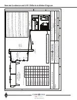
Electrical Interlock
Each module has Circuit 1 and Circuit 2 Condensing Unit
Interlocks to allow each respective condenser circuit to be
enabled only when that compressor circuit is enabled . Each
condenser 24 VAC control circuit is enabled through the R1
or R2 N .O . control relay of the respective chiller module .
Each module will require 2 pair of wires to be ran from
the module LVTB1 terminals 10 and 11 (C1), and terminals
12 and13 (C2) and connect to TB1 (C1) and TB2, (C2) at the
condenser it is piped to . See attached wiring diagram
examples for the chiller module and the remote condenser .
Summary of Contents for CLIMACOOL UCR 30
Page 19: ...17 www climacoolcorp com Voltage Phase Monitor Wiring Diagram...
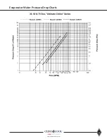
Page 29: ...27 www climacoolcorp com Evaporator Water Pressure Drop Charts...
Page 30: ...28 www climacoolcorp com Glycol Performance Adjustments Factor Charts...
Page 78: ...76 www climacoolcorp com Wiring Diagram...
Page 79: ...77 www climacoolcorp com Wiring Diagram...
Page 80: ...78 www climacoolcorp com Wiring Diagram CoolLogic Control Panel...
Page 81: ...79 www climacoolcorp com Wiring Diagram CoolLogic Control Panel...


