21
www.climacoolcorp.com
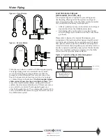
Service Ports (3/4”)
Isolation Ball Valves
(2 or 2-1/2”)
Pete’s Ports
Heat Exchanger
Leaving Chilled Water
Temperature Sensor
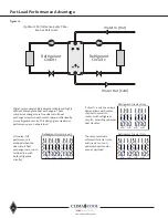
Refrigerant Circuit #1
Refrigerant Circuit #2
Hydronic Refrigeration
Figure 15 - Chilled Water Circuit
Note:
Figure 15 depicts hydronic piping in each ClimaCool chiller module and is shown with water isolation valves .
Summary of Contents for CLIMACOOL UCR 30
Page 19: ...17 www climacoolcorp com Voltage Phase Monitor Wiring Diagram...
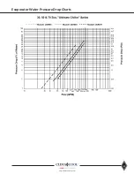
Page 29: ...27 www climacoolcorp com Evaporator Water Pressure Drop Charts...
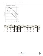
Page 30: ...28 www climacoolcorp com Glycol Performance Adjustments Factor Charts...
Page 78: ...76 www climacoolcorp com Wiring Diagram...
Page 79: ...77 www climacoolcorp com Wiring Diagram...
Page 80: ...78 www climacoolcorp com Wiring Diagram CoolLogic Control Panel...
Page 81: ...79 www climacoolcorp com Wiring Diagram CoolLogic Control Panel...

