Performance Verification
N-550
21
•
Test 3: Modulation
— This procedure simulates an O
XI
M
AX
sensor
attached to a patient indicating low and high pulse strength. The test
setup procedure sets up Test 3 for low pulse strength.
•
Test 4: Light
— This procedure simulates an O
XI
M
AX
sensor
attached to a patient indicating low and high light level passing
through the patient at the sensor site. The test setup procedure sets up
Test 4 for low light level.
Initial Setup
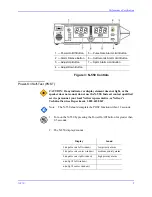
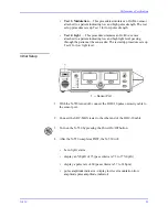
1 — Sensor Port
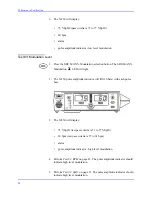
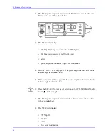
1. With the N-550 turned off, connect the DOC-10 pulse oximetry cable to
the sensor port.
2. Connect the SRC-MAX tester to the other end of the DOC-10 cable.
3. Turn on the N-550 by pressing the Power On/Off button.
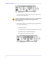
4. After the N-550 completes POST, the N-550 will:
•
be in SpO
2
alarm
•
display an %SpO
2
of 75 (pass criteria is 73 to 77 %SpO
2
)
•
display a pulse rate of 60 (pass criteria is 57 to 63 bpm)
•
pulse amplitude indicator - display low level modulation (low
amplitude pulse amplitude indicator)
Summary of Contents for OxiMax N-550
Page 1: ...N 550 Pulse Oximeter Service Manual min min SpO2 N 550 SatSeconds SpO2 ...
Page 10: ...Blank Page ...
Page 38: ...Blank Page ...
Page 64: ...Blank Page ...
Page 81: ...Disassembly Guide N 550 71 Figure 39 Equipotential Ground Terminal Removed ...
Page 82: ...Blank Page ...
Page 86: ...Spare Parts 76 Figure 40 Exploded View ...
Page 90: ...Blank Page ...
Page 108: ...Blank Page ...
Page 120: ...Blank Page ...
Page 130: ...Figure 56 Main PCB Parts Locator Diagram 129 Technical Description N 550 ...
Page 131: ...Figure 57 Front Panel Parts Locator Diagram 131 N 550 Technical Description ...
Page 136: ...Blank Page ...
Page 137: ... ...

