Data Port Interface Protocol
N-550
93
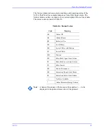
Nurse Call Polarity Settings
Nurse Call Relay Pin States
Nurse Call Relay Rating
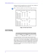
Real-Time Printout
When a real-time printout is being transmitted, a new line of data is printed
every two seconds. Every 25
th
line will be a Column Heading line. A Column
Nurse Call Polarity
Alarm State
Voltage at pins
10 to 11
Normally High
No alarm or Alarms Silenced
5 to 12 VDC
Audible Alarm
-5 to -12 VDC
Normally Low
No alarm or Alarms Silenced
-5 to -12 VDC
Audible Alarm
5 to 12 VDC
Pin
No Alarm or
Alarm Silenced
Audible Alarm
N-550 Turned
Off
7 N.O.
Open
Closed
Closed
8 N.C.
Closed
Open
Open
Maximum input voltage
30 VAC or 30 VDC
Load current
12 mA continuous (peak 300 mA at 100 msec)
Minimum resistance
26.5 ohms to 50 ohms (40.5 ohms typical during
alarms
Ground reference
isolated ground
Electrical isolation
1,500 V
Summary of Contents for OxiMax N-550
Page 1: ...N 550 Pulse Oximeter Service Manual min min SpO2 N 550 SatSeconds SpO2 ...
Page 10: ...Blank Page ...
Page 38: ...Blank Page ...
Page 64: ...Blank Page ...
Page 81: ...Disassembly Guide N 550 71 Figure 39 Equipotential Ground Terminal Removed ...
Page 82: ...Blank Page ...
Page 86: ...Spare Parts 76 Figure 40 Exploded View ...
Page 90: ...Blank Page ...
Page 108: ...Blank Page ...
Page 120: ...Blank Page ...
Page 130: ...Figure 56 Main PCB Parts Locator Diagram 129 Technical Description N 550 ...
Page 131: ...Figure 57 Front Panel Parts Locator Diagram 131 N 550 Technical Description ...
Page 136: ...Blank Page ...
Page 137: ... ...

