Audible Alarm Settings and Service Functions
40
Menu Item 12 (Silence Alarms)
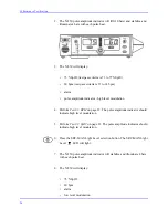
This option is used to set the alarm silence condition. Two options can be
accessed by first pressing the
SatSeconds
Alarm Limit button, then using the
Adjust Up or Adjust Down button to scroll to the desired option.
•
Option 0 = On - the N-550 will not display any alarm conditions (both
audio and visual).
•
Option 1 = Off - the N-550 displays alarm as selected by menu item
11.
When the desired option is indicated in the %SpO
2
display, press the
SatSeconds
Alarm Limit button to set the current selection. This setting will
remain in effect until the N-550 is turned off. The default selection (Option 1)
will be activated the next time the N-550 is turned on.
Menu Item 13 (All Display Off)
This menu item is used to enable or disable the display of the N-550. With
menu item 13 selected, press the
SatSeconds
Alarm Limit button, then use the
Adjust Up or Adjust Down button to scroll to the desired option.
•
Option 0 = is On, all normal display is enabled
•
Option 1 = is Off, all normal display is disabled
When the desired option is indicated in the %SpO
2
display, press the
SatSeconds
Alarm Limit button to set the current selection.
If Option “1” Off is selected, all visual display is turned off. Audio sound
cannot be set to off when Option “1” is selected. When any button is pressed,
all visual displays turn on.
Menu Item 14 (Alarm Sound Style Select)
This menu item is used to select the alarm sound style. With menu item 14
selected, press the
SatSeconds
Alarm Limit button, then use the Adjust Up or
Adjust Down button to scroll to the desired option.
•
Option 1 = Nellcor style
•
Option 2 = sound in accordance with IEC 60601-1-8
•
Option 3 = sound in accordance with EN 475
Summary of Contents for OxiMax N-550
Page 1: ...N 550 Pulse Oximeter Service Manual min min SpO2 N 550 SatSeconds SpO2 ...
Page 10: ...Blank Page ...
Page 38: ...Blank Page ...
Page 64: ...Blank Page ...
Page 81: ...Disassembly Guide N 550 71 Figure 39 Equipotential Ground Terminal Removed ...
Page 82: ...Blank Page ...
Page 86: ...Spare Parts 76 Figure 40 Exploded View ...
Page 90: ...Blank Page ...
Page 108: ...Blank Page ...
Page 120: ...Blank Page ...
Page 130: ...Figure 56 Main PCB Parts Locator Diagram 129 Technical Description N 550 ...
Page 131: ...Figure 57 Front Panel Parts Locator Diagram 131 N 550 Technical Description ...
Page 136: ...Blank Page ...
Page 137: ... ...

