Audible Alarm Settings and Service Functions
N-550
31
5
-
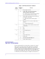
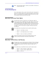
EPP Mode
1
Real Time ASCII
2
External equipment communications
6
-
In-sensor Trend Mode
0
Event SpO
2
1
Event SpO
2
+ Pulse Rate
2
Not use in-sensor trend function
7
-
RS-232 and RS-422 Nurse Call polarity (negative -
low, positive - high)
0
Positive on alarm, normally negative
1
Negative on alarm, normally positive
8
-
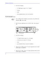
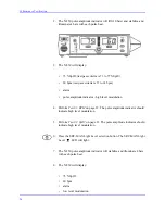
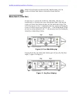
Time Set - Each display “-XX” (“-” means Selected.
“XX” means Numbers) Use Adjust Up/Adjust Down
buttons to change numbers. Use
SatSeconds
Alarm
Limit button to save selection.
Year
1
ST
display — “-XX” at left numeric display
Month
1
ST
display — “-XX” at right numeric display
Day
2
ND
display — “-XX” at left numeric display
Hour
2
ND
display — “-XX” at right numeric display
Minute
3
RD
display — “-XX” at left numeric display
Second
3
RD
display — “-XX” at right numeric display
9
-
Save current N-550 parameters to institutional
(Power-On default settings)
10
-
Restore N-550 parameters to factory default settings
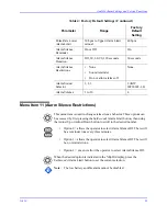
Table 2: N-550 Menu Selections (Continued)
Menu
Number
Sub-Menu
Number
Function
Summary of Contents for OxiMax N-550
Page 1: ...N 550 Pulse Oximeter Service Manual min min SpO2 N 550 SatSeconds SpO2 ...
Page 10: ...Blank Page ...
Page 38: ...Blank Page ...
Page 64: ...Blank Page ...
Page 81: ...Disassembly Guide N 550 71 Figure 39 Equipotential Ground Terminal Removed ...
Page 82: ...Blank Page ...
Page 86: ...Spare Parts 76 Figure 40 Exploded View ...
Page 90: ...Blank Page ...
Page 108: ...Blank Page ...
Page 120: ...Blank Page ...
Page 130: ...Figure 56 Main PCB Parts Locator Diagram 129 Technical Description N 550 ...
Page 131: ...Figure 57 Front Panel Parts Locator Diagram 131 N 550 Technical Description ...
Page 136: ...Blank Page ...
Page 137: ... ...


