


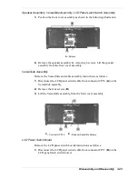
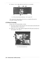


Disassembly and Reassembly 3-27
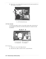
Buzzer
1.
Disconnect the buzzer cable from connector P29 on the main board.
2.
Pry up to remove the buzzer assembly from its location.
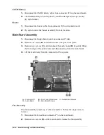
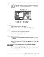
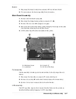
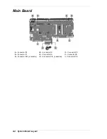
Main Board Assembly
1.
Remove the main board screws (
A
).
2.
Disconnect the bridge battery cable at connector P1 (
B
).
3.
Remove the one screw (
D
) and port cover plate.
3.
Disconnect the audio board (
C
) by gently lifting the front edge of the audio
board and disconnecting from the main board.
4.
Lift the main board from the remainder of the system.
A – Main Board Screws
B – Connector P1
C – Audio Board
D – Port Cover Plate Screw
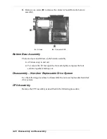
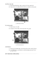
Fan Assembly
The fan assembly is made up of a bracket and fan. Follow the steps below to
remove.
1.
Disconnect the fan cable at connector P5 on the main board.
2.
Remove two screws (
D
) on the main board to release the fan assembly.
3.
Remove two screws to release the fan from the bracket.
CPU Assembly
The CPU assembly may also be removed from the bottom on the system, as
described in Disassembly Sequence 3 (CPU Assembly).
Summary of Contents for Versa LX
Page 1: ...NEC Versa LX Notebook Computer VERSA LX S E R V I C E A N D R E F E R E N C E M A N U A L...
Page 57: ...3 Disassembly and Reassembly Required Tools and Equipment Disassembly Reassembly...
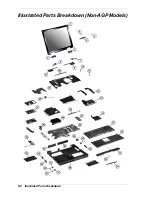
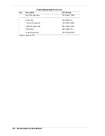
Page 91: ...5 2 Illustrated Parts Breakdown Illustrated Parts Breakdown Non AGP Models...
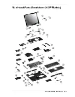
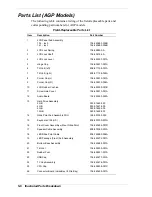
Page 94: ...Illustrated Parts Breakdown 5 5 Illustrated Parts Breakdown AGP Models...
Page 102: ...7 Troubleshooting Quick Troubleshooting Helpful Questions...