2-4 System Configuration and Setup
!
CAUTION
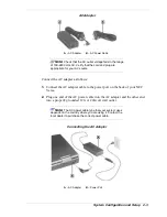
Do not cover or place objects on the AC adapter. Keeping
the adapter clear of objects lets the adapter cool properly
during use.
Powering On
Power on the system as follows:
1.
Locate the latch on the front of the LCD panel, slide it to the right, and raise
the panel.
2.
Locate the Power/Sleep button and slide it toward the front of the system to
turn on system power.
Using the Main Battery Pack
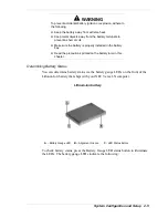
The NEC Versa comes with a rechargeable Lithium-Ion (Li-Ion) battery pack.
You can run your system on battery power for approximately two to four hours
with power management features enabled. It’s easy to install and remove.
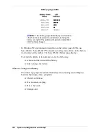
Your NEC Versa system provides tools to help you keep track of the main (or
an optional) battery’s power level. These include the power status LED
described in Chapter 1, and SystemSoft’s PowerProfiler™ (for Window NT
systems, only) described later in this chapter. Both provide important battery
status information.
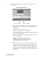
When battery power is very low, the power LED flashes amber.
When battery power gets low, do one of the following:
Slide the Power/Sleep button toward the front of the system and hold it in
place for 4 or fewer seconds to put your system in Suspend mode. (Before
using the Power/Sleep button to put the system into Suspend mode set the
System Switch BIOS parameter to Sleep button.) Remove the battery pack
and replace it with a fully charged battery.
Suspend in Windows 95 from the Start menu.
Leave the battery pack in the system and connect your NEC Versa to the
AC adapter and a wall outlet. If you connect the system to AC power and
keep the system within standard operating temperatures, the battery
recharges in approximately 2–3 hours whether or not you use your
system.
You can also buy an optional NEC Versa battery charger to charge your battery.
See the NEC CSD web site at http://www.nec-computers.com/.
Summary of Contents for Versa LX
Page 1: ...NEC Versa LX Notebook Computer VERSA LX S E R V I C E A N D R E F E R E N C E M A N U A L...
Page 57: ...3 Disassembly and Reassembly Required Tools and Equipment Disassembly Reassembly...
Page 91: ...5 2 Illustrated Parts Breakdown Illustrated Parts Breakdown Non AGP Models...
Page 94: ...Illustrated Parts Breakdown 5 5 Illustrated Parts Breakdown AGP Models...
Page 102: ...7 Troubleshooting Quick Troubleshooting Helpful Questions...

