System Configuration and Setup 2-29
Connecting VersaBay III Adapter Kit Cables
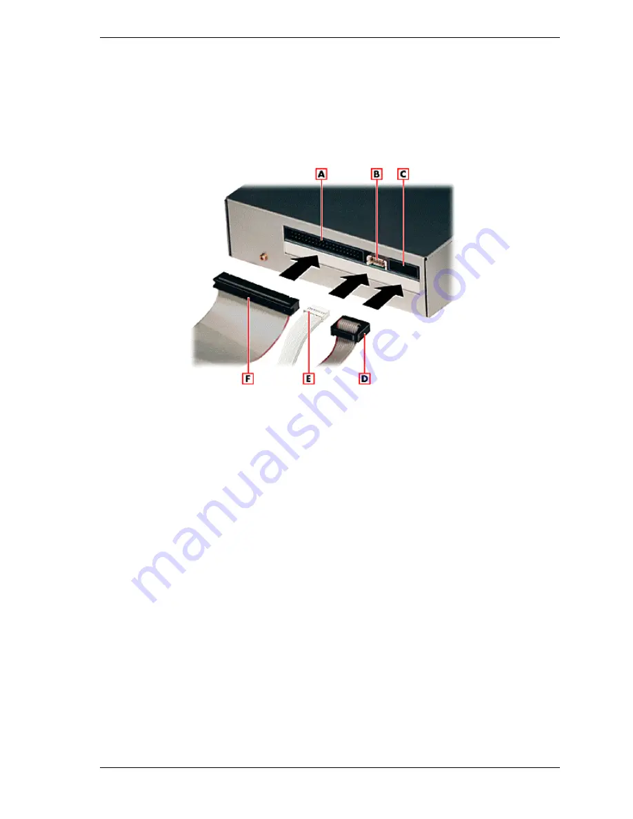
Connect the VersaBay III Adapter Kit cables as follows.
1.
Locate the IDE cable port, the VersaBay III signal cable port, and the
VersaBay III power cable port.
Locating and connecting the cables to the VersaBay III device
A
- IDE signal cable port
B
- Power cable port
C
- VersaBay III cable port
D
- VersaBay III cable
E
- Power cable
F
- IDE signal cable
2.
Connect the cables to the appropriate ports on the back of the optional
VersaBay III Adapter Kit.
You are now ready to install the optional VersaBay III Adapter Kit into the file
bay. (See the instructions in “File Bay Installation” for details.)
File Bay Installation
Install an IDE device or the optional VersaBay III Adapter Kit in the file bay as
follows.
1.
Before handling any internal components, discharge static electricity from
yourself and your clothing by touching a nearby metal surface.
2.
Remove the NEC Versa Dock front panel, docking tray, and cable cover.
(See the instructions in “Removing Trays, Panels, and Covers” for details.)
3.
Remove the cables from the motherboard. (See the instructions in
“Disconnecting Cables from the Motherboard” for details.)
Summary of Contents for VERSA DOCK - SERVICE
Page 33: ...System Configuration and Setup 2 17 ...
Page 67: ...3 Disassembly and Reassembly n Required Tools and Equipment n Disassembly n Reassembly ...
Page 74: ...3 8 Disassembly and Reassembly Removing the bracket ...
Page 83: ...4 System Board Layout n Main Board n LED Board n PCI Expansion Board ...
Page 84: ...4 2 System Board Layout Main Board LED Board ...
Page 85: ...System Board Layout 4 3 PCI Expansion Board ...
Page 86: ...5 Illustrated Parts Breakdown n NEC Versa Dock Illustrated Parts Breakdown n Parts List ...
Page 87: ...5 2 Illustrated Parts Breakdown NEC Versa Dock Illustrated Parts Breakdown ...
Page 88: ...Illustrated Parts Breakdown 5 3 ...
Page 95: ...7 Troubleshooting n Quick Troubleshooting n Helpful Questions ...


