background image

A-10      Connector Pin Assignments

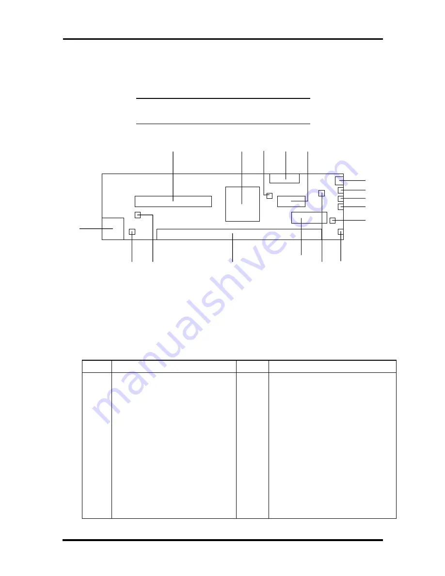
RISER CARD CONNECTOR LOCATIONS

Figure A-7 shows the locations of connectors on the riser card.


NOTE:

   Not all of the riser card connectors and

functions are used in all configurations.


Figure A-7   Riser Card Component and Connector Locations

The following table describes the riser card components and connectors shown in the
previous figure.

 Table A-10  Riser Card Connectors and Components

 Letter

 Description

 Letter

 Description

 A

 PCI Connector (J3C1)

 J

 Modem Remote Wake Up

 B

 Intel PRO100B LAN Controller

 K

 Fan Header (J4L2)

 C

 Fan Speed Control Jumper (J3G1)

 L

 Front Panel System Reset Header
(J2L2)

 D

 Floppy Connector

 M

 Diskette Drive Connector (J2H1)

 E

 Power Connector (J3J1)

 N

 NLX System Board Connector (J4G1)

 F

 Power On Switch (J2L1)

 O

 LAN Enable/Disable Jumper (J3B1)

 G

 Power/Sleep/Off LED
(Green/Yellow/Off)

 P

 Card Remote Wake-Up (J4B1)

 H

 HDD Activity LED (Green)

 Q

 RJ-45 LAN Connector (J4A1)

 I

 LAN Activity LED (Green)

 R

 IDE Connector (J4J1)


A

Q

P

O

N

M

L

K

J

I

H

G

F

E

D

C

B


R

F

G

H

I

J

K

L

M

Summary of Contents for POWERMATE ENTERPRISE NETPC - SERVICE

Page 1: ...arranty Statement accompanying each product However actual performance of each such product is dependent upon factors such as system configuration customer data and operator control Since implementation by customers of each product may vary the suitability of specific product configurations and applications must be determined by the customer and is not warranted by NECCSD To allow for design and s...

Page 2: ...ing the system with the BIOS Setup utility setting passwords using power management and security features reinstalling the operating system or software and using the BIOS Update utility Section 3 Option Installation provides installation procedures for adding optional expansion boards upgrading the hard disk adding system memory or upgrading the processor NOTE Access to the inside of the system is...

Page 3: ...ts provides a list of system riser and option board internal connector pin assignments and a list of external pin assignments for the keyboard mouse serial ports parallel port network ports and video port Appendix B Jumper Settings provides jumper settings for the system board and for options that may ship with the computer including the CD ROM reader and the fax modem board ...

Page 4: ...direct current DIMM Dual In Line Memory Module DIP dual in line package DLAB Divisor Latch Address bit DMA direct memory access DMAC DMA controller DOS disk operating system DRAM dynamic RAM ECC error checking and correction EDO extended data output EGA Enhanced Graphics Adapter EPROM erasable and programmable ROM EVGA Enhanced Video Graphics Array F Fahrenheit FAX facsimile transmission FCC Feder...

Page 5: ...ier PLL phase lock loop p p peak to peak PPI programmable peripheral interface PROM programmable ROM QFP quad flat pack RAM random access memory RAMDAC RAM digital to analog converter RAS row address strobe RGB red green blue RGBI red green blue intensity ROM read only memory rpm revolutions per minute R read RTC real time clock R W read write S slave SCSI Small Computer System Interface SDRAM Syn...

Page 6: ...Abbreviations xvii ...

Page 7: ...re Monitor 1 12 Interrupt Controller 1 12 Plug and Play 1 15 Chassis 1 15 PCI Local Bus 1 15 PCI IDE Ports 1 16 Parallel Interface 1 16 Serial Interface 1 17 USB Interface 1 19 Video Interface 1 19 Integrated Audio 1 20 Diskette Drive Support 1 21 Hard Disk Drive 1 21 Power Supply 1 21 Riser Card 1 22 Mouse 1 22 Keyboard 1 22 Specifications 1 23 Section 2 Setup and Operation Site Selection 2 1 Ins...

Page 8: ...13 System Time Date 2 13 Floppy Options 2 14 Primary IDE 2 14 Advanced Menu 2 16 PnP O S 2 16 Reset Configuration Data 2 16 Memory Cache 2 16 Memory Banks 0 and 1 2 16 Resource Configuration 2 16 Peripheral Configuration 2 17 Keyboard Configuration 2 19 DMI Event Logging 2 19 Security Menu 2 20 User Password Is 2 20 Supervisor Password Is 2 20 Set User or Supervisor Password 2 20 Clear User Passwo...

Page 9: ...6 Section 3 Option Installation General Rules 3 1 Safety Precautions 3 2 Required Tools 3 3 Internal Access 3 4 Removing the System Unit Top Cover 3 4 Opening the System Chassis 3 5 Closing the System Chassis 3 7 Replacing the System Unit Top Cover 3 8 Expansion Board 3 8 Installing an Expansion Board 3 9 Removing an Expansion Board 3 11 DIMM Upgrade 3 12 Checking System Memory 3 12 Removing a DIM...

Page 10: ...Cleaning 4 8 Troubleshooting 4 9 Diagnosing and Solving Problems 4 9 Replacing the CMOS Battery 4 13 Section 5 Disassembly and Reassembly Safety Procedures 5 1 Recommended Tools 5 3 Removal and Replacement 5 3 System Unit Top Cover 5 4 Removal 5 4 Replacement 5 5 Front Bezel 5 6 Removal 5 6 Replacement 5 7 Battery 5 7 EMI Shield 5 8 Removal 5 8 Replacement 5 9 EMI Clip Riser Card 5 10 Removal 5 10...

Page 11: ...ly Fan Top Chassis 5 24 Removal 5 24 Replacement 5 26 Processor 5 27 Removal 5 27 Replacement 5 28 Riser Card 5 29 Removal 5 29 Replacement 5 30 Depot Level Parts List 5 31 Appendix A Connector Pin Assignments System Board Connector Locations A 1 Parallel Interface Connector A 3 Serial Interface Connectors A 4 Keyboard and Mouse Connectors A 5 VGA Interface Connector A 6 Line In Connector A 7 Line...

Page 12: ...rd Jumpers B 1 Changing Processor Jumper Settings B 2 Clearing a Password B 4 Normal Mode B 5 Configure Mode B 6 Recovery Mode B 6 Riser Card B 7 Riser Card Fan Speed Control Jumper B 8 LAN Enable Disable Jumper B 8 Index Figures 1 1 Powermate NetPC Features Front View 1 2 1 2 Powermate NetPC Features Back View 1 2 1 3 Top and Bottom Chassis Assemblies 1 3 1 4 Chassis Hardware Features 1 4 2 1 Com...

Page 13: ...nit Cover 3 8 3 8 Removing the Slot Cover and Retaining Bracket 3 10 3 9 Installing an Expansion Board 3 11 3 10 Removing a DIMM 3 13 3 11 Releasing the Processor 3 15 3 12 Removing the Hard Disk Screws and Cables 3 17 3 13 Hard Disk Cable Connections 3 18 4 1 Removing the Keyboard Enclosure 4 7 4 2 Removing the Mouse Ball Cover 4 8 4 3 Locating the Battery 4 14 4 4 Removing the Battery 4 14 5 1 R...

Page 14: ...moving the Processor 5 28 5 24 Separating the System Board and Riser Card 5 29 5 25 Installing the EMI Clip On the Riser Card 5 30 5 26 Powermate NetPC Illustrated Parts Breakdown 5 33 A 1 System Board External Connector Locations A 1 A 2 System Board Internal Connector Locations A 2 A 3 Parallel Interface Connector A 3 A 4 Serial Interface Connectors A 4 A 5 PS 2 Style Keyboard and Mouse Interfac...

Page 15: ...29 1 21 Riser Card Specifications 1 30 2 1 Power Supply Voltage Rating 2 3 2 2 Power LED Functions 2 7 2 3 Navigation Keys 2 12 4 1 NECCSD Service and Support Telephone Numbers 4 1 4 2 Problems and Solutions 4 9 5 1 Parts Removal and Replacement 5 3 5 2 Service and Ordering Information 5 31 5 3 PowerMate NetPC Depot Level Parts List 5 32 5 4 PowerMate NetPC Documentation and Packaging 5 34 A 1 Sys...

Page 16: ... Pin Assignments A 11 A 14 Modem Remote Wake up Pin Assignments A 12 A 15 Diskette Drive Pin Assignments A 12 A 16 IDE Interface Pin Assignments A 13 A 17 PCI Bus Pin Assignments A 14 A 18 Power Connector Pin Assignments A 15 A 19 RJ 45 Connector Pin Assignments A 16 B 1 Processor Bus Speed Jumper Settings B 3 B 2 Fan Speed Control B 7 B 3 LAN Enable Jumper Pin Assignments B 7 ...

Page 17: ... 200 MHz Intel Pentium MMX processsor 32 MB of SDRAM and a 3 2 GB hard disk drive The MMX processor technology boosts audio video and 3D graphics performance Both PowerMate NetPC models come with an RJ 45 network connector and a video chip with 2 MB of Synchronous Graphics Random Access Memory SGRAM Both models also contain audio video components for multimedia presentations and support optional m...

Page 18: ...1 2 Technical Information Figure 1 1 PowerMate NetPC Features Front View Figure 1 2 PowerMate NetPC Features Back View ...

Page 19: ...e the PowerMate NetPC are listed below Intel CN430TX system board Intel Pentium 166 MHz MMX processor Intel Pentium 200 MHz MMX processor RJ 45 LAN connector on riser card for connection to an Ethernet network Two 168 pin DIMM sockets system memory from 16 MB using 16 MB 32 MB and per availability 64 MB or 128 MB sticks upgradeable to 256 MB S3 Trio 64 ViRGE GX graphics chip integrated on system b...

Page 20: ...Board Intel CN430TX with sound CPU Pentium 166 MHz MMX Pentium 200 MHz MMX System RAM 16 MB to 256 MB of SDRAM in 2 DIMM sockets IDE Hard Disk Drive Western Digital Ultra DMA 33 2 0 GB WDAC22000 3 2 GB WDAC33200 L2 Cache 256 KB Graphics S3 Trio 64 ViRGE GX 3D Graphics on system board Video DRAM 2 MB of SGRAM soldered on system board Varies by system Hard Disk DIMM Sockets System Board Processor He...

Page 21: ...to 256 MB of SDRAM using DIMMs PTL BIOS in a flash memory device supporting system setup and PCI auto configuration the NetPC BIOS is slightly different than the standard PC BIOS boot from CD ROM is not an option since this device is not integrated into the system Expansion slot for riser card PS 2 style keyboard and mouse connectors 32 KB internal dual write back cache integrated on the MMX proce...

Page 22: ...ssis NOTE The system supports only one Ultra DMA 33 device on the IDE channel If an additional IDE device is added to the IDE channel neither device can use Ultra DMA 33 mode Power management with power saving mode featuring inactivity timer External connectors for connecting the following external devices VGA compatible monitor standard super high resolution VGA Personal system 2 PS 2 style mouse...

Page 23: ...ra DMA 33 enhanced DMA controller and interrupt controller based on 82C95 with support for 15 interrupts power management control real time clock 16 bit counters National Heceta LM78 Provides voltage temperature and security monitoring PC87307VUL I O Controller Multimode parallel port Centronics compatible standard mode Enhanced capabilities port ECP Enhanced parallel port EPP Two RS 232C serial p...

Page 24: ...ory device on the system board The BIOS provides the Power On Self Test POST the system Setup program a PCI and IDE auto configuration utility and BIOS recovery code The system BIOS is always shadowed Shadowing allows any BIOS routine to be executed from fast 32 bit DRAM on the system board instead of from the slower 8 bit flash device NEC s Flash ROM allows fast economical BIOS upgrades The Flash...

Page 25: ...programming of the system BIOS and the video BIOS The system memory map is shown in Table 1 3 Table 1 3 System Memory Map Memory Space Size Function 100000 10000000 256 MB Extended memory F0000 FFFFF 64 KB PTL system BIOS EC000 EFFFF 16 KB Reserved for BIOS EA000 EBFFF 8 KB ECSD Plug and Play configuration and DMI E9000 E9FFF 4 KB Reserved for BIOS E8000 E8FFF 4 KB OEM logo or Scan User Flash E400...

Page 26: ...Natural Keyboard 0071 System CMOS real time clock 0078 007F System board resources 0080 System board resources 0081 008F DMA controller 00A0 00A1 Programmable interrupt controller 00C0 00DF DMA controller 00F0 00FF Numeric data processor 01F0 01F7 Intel 82371AB PCI Bus Master IDE controller 01F0 01F7 Primary IDE controller dual FIFO 0220 022F YAMAHA OPL3 SAx Sound System 0274 0277 I O read data po...

Page 27: ...E controller FCD0 FCD7 Primary IDE controller dual FIFO FCE0 FCFF Intel EtherExpress Pro 100 WfM PCI adapter System Memory The system comes with between 16 MB and 256 MB of SDRAM installed in dual in line memory module DIMM sockets on the system board The memory configuration consists of two sockets The DIMM memory sockets accept 168 pin 64 bit non parity 8 16 32 64 and 128 MB DIMMs Table 1 5 list...

Page 28: ... or low voltage levels registers for storing POST hardware test results and error codes remote reset capabilities from a remote peer or server through LANDesk Client Manager v 3 0 When ranges for temperature fan speed or voltage are exceeded an interrupt is activated The hardware monitor component connects to the ISA bus as a 8 bit I O mapped device Interrupt Controller The interrupt controller op...

Page 29: ... Floppy Disk Floppy Disk 7 Parallel Port LPT1 OPL3 SAX 8 RTC Clock Calendar RTC Clock Calendar 9 S3 Virge DX GX PCI Intel 82371AB USB Serial Port S3 Virge DX GX PCI Intel 82371AB USB Serial Port 10 Not used Not used 11 Intel Ether Express Pro 100 PCI Intel Ether Express Pro 100 PCI 12 Mouse Mouse 13 Coprocessor Coprocessor 14 IDE port A IDE port A 15 NA NA In Plug and Play systems these interrupts...

Page 30: ... may vary by configuration See the following paragraphs The following audio resources vary depending on which operating system or environment they run under default based on shipping configurations Base I O address 220 22f FM Synthesis address 388 38B MPU 401 MIDI address 330 331 The following information indicates the possible resources that a sound component can have after third party devices ha...

Page 31: ...ns of the chassis are included in Table 1 16 Power connections to the system board are carried through the riser card which also contains the half length PCI card slot PCI Local Bus The 32 bit PCI bus is the primary I O bus for the system The PCI bus is a highly integrated I O interface that offers the highest performance local bus available for the Pentium processor The bus supports burst modes t...

Page 32: ...rt on the system board Port specifications conform to the IBM PC standards The port supports Enhanced Capabilities Port ECP and Enhanced Parallel Port EPP modes for devices that require ECP or EPP protocols The protocols allow high speed bi directional transfer over a parallel port and increase parallel port functionality by supporting more devices The BIOS has automatic ISA printer port sensing t...

Page 33: ... The serial ports support the standard RS 232C interface The buffered high speed serial ports support transfer rates up to 115 2 KB These ports allow the installation of high speed serial devices for faster data transfer rates Sets of I O addresses and interrupt levels for the two channels are given in Table 1 9 and Table 1 10 Note that COM2 is disabled by default The interrupt levels are selectab...

Page 34: ...Level Port 3F8 IRQ04 COM1 3F8 IRQ03 COM1 3E8 IRQ04 COM3 3E8 IRQ03 COM3 Table 1 10 Serial Port 2 Addresses and Interrupts Starting I O Address Interrupt Level Port 3F8 IRQ04 COM1 2F8 IRQ03 COM2 3E8 IRQ04 COM3 3F8 IRQ03 COM1 2F8 IRQ04 COM2 3E8 IRQ03 COM3 See Section 2 Setup and Operation for information on resetting the port through the Setup utility Serial interface specifications include Baud rate...

Page 35: ...keyboard instead of a standard keyboard Video Interface The system board features the S3 Trio 64 ViRGE GX 3D accelerator chip with 2 MB of video SGRAM soldered on the system board The video and graphics controller accelerates color space conversion and video upscaling to deliver exceptional graphics and high quality MPEG and video playback and true multimedia functionality MPEG is a compression de...

Page 36: ... Yamaha OPL3 SA3 chip is integrated on the system board The chip provides 16 bit stereo Sound Blaster Pro compatible audio System boards with audio provide a line out jack and microphone jack The sound system provides all the digital and analog mixing functions required for playing and recording audio on personal computers Features include stereo analog to digital and digital to analog converters ...

Page 37: ...ector primary only for connecting IDE storage devices such as hard disk drives Logically the connector supports up to two IDE devices Physically there is room for one hard disk in the chassis An optional second hard disk drive can be added to the primary channel if the cable is replaced with a three connector IDE cable If an additional hard disk drive is added to the primary IDE channel configure ...

Page 38: ...nector for connecting the system to an Ethernet network The card also contains a PCI expansion slot for installing a half length PCI expansion board The riser card connects to the system board through a 170 pin edge connector and also cable connects to the power supply to provide DC power to the NetPC system components The riser card contains one primary IDE connector for the system s hard disk an...

Page 39: ... System Memory From 16 MB to 256 MB in two DIMM sockets on system board Optional DIMMs 16 MB 32 MB 64 MB as available and 128 MB as available 168 pin 64 bit non parity DIMMs Video Accelerator S3 ViRGE 2D 3D video graphics accelerator 170 MHz RAMDAC and clock synthesizer integrated in a single chip S3 Streams Processor technology for video playback Graphics Support 1280 by 1024 pixels up to 256 col...

Page 40: ...atures 2 button with cursor movement wheel X Y encoder resolution 400 PPI opto mechanical Wheel Resolution zoom resolution 18 counts per revolution Operating Characteristics Vin 115 V or 230 V as appropriate Ta 25 Thermal stabilization 1 hour minimum Physical Features Length 4 53 inches Width at head 2 25 inches Width at hips 2 6 inches Height 1 52 inches Weight 170 grams 1 20 grams Temperature Ra...

Page 41: ...t VGA monitor port Two universal serial bus ports Two audio connectors line in line out Front Panel Power button Power Suspend state indicator lamp Hard disk drive busy indicator lamp LAN activity lamp Table 1 17 2 0 GB Hard Disk Drive Specifications Feature Specification Hard Disk Drive 2 0 GB Western Digital Caviar WDAC22000 LLA Physical Configuration Formatted Capacity Number of Disks Data Surf...

Page 42: ...indle Stop Time typical 6 sec Start Stop Cycles minimum 40 000 MTBF 350 000 hours MTTR 10 minutes Data Reliability 1 unrecoverable error per 10 13 bits read Actuator Rotary voice coil Interface 40 pin EIDE bus connector Temperature non condensing Operating 5 to 55 C 41 to 131 F Non operating 40 to 60 C 40 to 138 F Humidity non condensing Operating 8 to 80 rh 33 C 94 6 F Non operating 5 to 95 rh 33...

Page 43: ...16 heads x 6 346 368 sectors Servo Type Embedded Recording Method GCR 8 9 PRML Performance Track to Track Seek typical 3 0 ms Average Seek Read Write 11 5 13 5 ms Maximum Seek Read Write 15 0 17 0 ms Average Latency 5 8 ms Rotation Speed 5200 RPM Data Transfer Rate Buffer to Disk Mbits s 114 max Buffer to Host Mbytes s 16 6 max Interleave 1 1 Buffer Size 256 Kbytes Power on to Ready typical 11 sec...

Page 44: ...s Height 1 0 inches 25 4 mm Width 4 0 inches 101 6 mm Depth 5 75 inches 146 1 mm Weight 1 1 lb 0 500 kg Table 1 19 Environmental Standards Parameter Condition Specification Temperature Non Operating 40 to 60 C T 20 C hr Operating 10 to 35 C T 10 C hr Humidity Non Operating 95 RH 25 30 C RH 9 hr T 5 C hr Shock Operating 0 001 g 2 Hz 5 Hz sloping to 0 01 g 2 Hz 20 Hz 0 01 g 2 Hz from 20 to 500 Hz Pa...

Page 45: ... 1 20 Power Supply Specifications Feature Specification Power Supply Form Factor CN430TX Net PC Open Frame Operating Characteristics Power 51 Watts maximum continuous for support of PFC Efficiency 65 at full load 60 Energy Star efficiency 18 Watts AC Line Line Voltage Frequency 90 132 180 264 VAC 47 63 Hz Source Interrupt Power drop out of 17 ms Surge 2 0 kV Unidirectional 3 0 kV Ringwave Voltage ...

Page 46: ...ler Support for Ultra DMA Support for up to 10 MB second 32 bit transfers on PCI bus Support for a total of two IDE devices 40 pin connector Support for PIO mode 3 and mode 4 PCI slot for half length board RJ 45 LAN connector System board slot Industry Standard Interface One PCI IDE connector for master and slave devices Diskette drive connector Fan connector ...

Page 47: ...er 5 for servicing and parts information SITE SELECTION The computer is designed to operate reliably in a normal office environment Make sure the site is well ventilated dust free and away from heat sources In addition choose a site according to the following criteria Place the computer on a desktop or other raised flat surface do not put the computer on the floor Place the computer near a grounde...

Page 48: ...the following figure To ensure proper cooling of the computer keep all vents clear of obstructions To ensure adequate air flow and reduce the risk of overheating or fire use the stand provided with the system for vertical tower placement of the computer Figure 2 1 Computer Vents INSTALLATION Install the computer according to the following procedures and safety standards Check the voltage switch Se...

Page 49: ... The voltage ratings for the power supply are provided in the following table Table 2 1 Power Supply Voltage Rating Voltage Input Frequency Hz Current Amps 100 127 60 2 200 240 50 1 25 Before connecting the power cable to the back panel of the computer make sure that the voltage selector switch is set to the correct AC line source voltage for your region For line voltages between 100 and 127 VAC s...

Page 50: ... computer is designed to sit in a horizontal or vertical position on a desktop or other surface away from the floor In the horizontal position the computer supports standard 15 inch monitors Figure 2 3 Horizontal Orientation For vertical placement use the stand provided in the computer shipping box ...

Page 51: ...ing Cables The following figure shows the connector locations on the back of the computer for connecting the keyboard mouse monitor and power cables The figure also shows the locations for other device cables in case you are installing additional hardware CAUTION Turn off and unplug the computer before connecting any cables to the back of the computer Equipment may be damaged if you connect cables...

Page 52: ...igure 2 5 Rear Panel Connectors Preventing Internal Access To prevent access to the inside of the computer install a padlock in the small padlock slot in the back of the system see the following figure Figure 2 6 Chassis Security ...

Page 53: ...ctrical power that could damage the computer s power supply and result in loss of data If the computer does not turn on press the power button on the front panel see the following figure Use the lamps on the front panel to verify that the power hard disk drive and LAN connections are working as follows Power on green Sleep mode yellow This LED indicates the operating status of the machine see Tabl...

Page 54: ...le must be connected to the LAN controller on the riser card Figure 2 7 Front Panel Controls and Indicators The power lamp lights green to indicate that the system is on The NEC startup screen appears At the bottom of this screen messages like the following appear Press F2 key if you want to run Setup Press ESC to display POST NOTE These messages are part of the system s Power On Self Test POST Th...

Page 55: ...ave changed run Setup see Setup Utility On PowerMate NetPC systems loaded with the Windows NT 4 0 operating system press Ctrl Alt Del when prompted on screen to do so The log on box appears for entering a password Shutting Down Follow these steps to shut down power off the computer 1 Save your work See the documentation that comes with the application 2 Exit the application program 3 Make sure tha...

Page 56: ... factory with the correct system parameters for the configuration Unless you add optional hardware you do not need to run Setup to operate the system However you might wish to run the Setup utility to set features that customize the system such as security features System configuration information is stored in nonvolatile memory A nonvolatile memory device retains its data when system power is tur...

Page 57: ...ed by Setup change certain system operating parameters such as boot device sequence and keyboard parameters configure system connections for peripherals such as devices connected to the printer port and serial ports customize the system with security features such as passwords virus check reminder and system backup reminder set system parameters in the event that the CMOS battery has been replaced...

Page 58: ...owing table describes the navigation keys Table 2 3 Navigation Keys Key Function F1 Provides help for the parameter field being displayed Esc Exits the menu Enter Executes Command or Selects submenu or arrow keys Moves cursor up and down or arrow keys Selects next menu or Selects parameter values in a menu F9 Loads the Default Configuration values for this menu F10 Save and Exit ...

Page 59: ...ut text are not available Explanations of each menu item follow Displayed Information The following information is displayed in the Main menu These fields are read only and cannot be changed Processor type Processor speed Cache RAM Total Memory BIOS version Language Selects the current language used by the BIOS Use this field to select English the default or German System Time Date Use this menu t...

Page 60: ...er and slave on the primary IDE channel Menu choices include Primary Master Primary Slave The default setting for existing installed Master devices is Auto meaning that the system automatically detects the hard disk type and sets the remaining parameters The default setting for existing installed Slave devices is None If a hard disk drive that does not feature auto IDE type detection has been inst...

Page 61: ...s include Disabled no sectors chosen Standard one sector 2 4 8 and 16 sectors LBA Mode Control When Enabled is selected it causes logical block addressing to be used in place of cylinders heads and sectors Transfer Mode Enter the method for transferring the data between the hard disk drive and the system memory The Setup menu only lists those options supported by the drive Choices can include Stan...

Page 62: ... area of static RAM SRAM which is faster Before accessing regular memory the CPU first accesses the cache If it does not find the data it is looking for it accesses the regular memory The default for the Memory Cache is Enabled This field controls both the primary and secondary caches Setting the Memory Cache to Disabled will hurt performance but might be required when running programs that utiliz...

Page 63: ...figuration Adjustments must sometimes be made in the Setup Utility when peripheral devices are added removed or changed Use the fields in the following list to configure the system when making any peripheral configuration changes Serial Ports A and B Selectable parameters for this field are Disabled Enabled and Auto The default setting for Serial Port A is Enabled The default setting for Serial Po...

Page 64: ...Capabilities Port ECP mode Disabled Output Only and Bi directional sets the parallel port to input output mode only The default setting is Bi directional Base I O address Available addresses include 378h the default 278h and 228h Interrupt Available IRQs include IRQ5 and IRQ7 the default DMA channel This field appears only when the Mode option is set to ECP it does not appear when the Mode option ...

Page 65: ...r off The default is Disabled Keyboard Auto Repeat Rate This field sets the number of times per second to repeat a keystroke when the key is held down Options include 2 6 10 13 3 18 5 21 8 26 7 or 30 clicks per second The default is 30 Keyboard Auto Repeat Delay This field controls the speed characters repeat when a keyboard key is held down The higher the number the faster the repeat Options incl...

Page 66: ... set This field can be either Clear or Set The default is Clear no password has been set When both the User Password and Supervisor Password are Enabled only the Supervisor Password gives you full access to all Setup fields Set User or Supervisor Password The password fields allow you to enable a user level password or supervisor level password during POST and to enter Setup Use the following proc...

Page 67: ... Setup To prevent the user from accessing Setup highlight the field and press Enter Then highlight Disabled and press Enter again Using a Password After you set the password in Setup and reboot the system a password prompt appears each time you power on the system To use the password type the password at the password prompt and press Enter NOTE For security characters you enter do not appear on th...

Page 68: ...or inactivity time periods include Off 5 10 20 the default or 30 minutes and 1 or 2 hours Hard Drive When this field is enabled the hard disk drive is powered down during periods of inactivity Choices include Enabled default and Disabled VESA Video Power Down This field enables you to set the video power down level of inactivity Choices include Disabled Sleep the most energy efficient setting Susp...

Page 69: ...ystem s drives boot up The default order is Diskette drive Hard disk LANDesk Service or network Hard Drive This field lists the bootable hard disk drives in the system as well as bootable ISA boards Use this field to change the booting order Boot Time Diagnostic screen When set to enabled this field allows you to display the Diagnostic Screen during boot up The default setting is Disabled Floppy C...

Page 70: ...S fails the BIOS will read the custom defaults if you set them If not the BIOS uses the factory default settings Discard Changes Choose this option if you wish to discard any changes made in the current session but want to continue to enter new changes FLASH UTILITY The system BIOS resides on a flash read only memory ROM chip in the system The flash ROM can be updated with a very simple procedure ...

Page 71: ...the BIOS defaults Then use the copy of the Setup selections you made at the beginning of this procedure to set the parameters LANDESK CLIENT MANAGER LANDesk Client Manager LDCM is a software program available on the NEC Select Install CD LDCM uses the Desktop Management Interface DMI standard to manage components network interface cards memory software applications within a Client local or remote ...

Page 72: ...sh the screen to view the new correct PC health You can also set the monitor to report only unhealthy workstations PC Health Meter The PC Health meter is a traffic signal that provides a visual indicator of workstation health A red light indicates that a critical system event has occurred You are required to fix the problem immediately A yellow light or noncritical system event requires that you m...

Page 73: ...o a log file Inventory Client Manager Inventory views the hardware and software components of the workstation The inventory consists of the following categories workstation summary basic hardware drives memory audio keyboard mouse video system resources I O ports operating system network applications system files user information You can also view the current system configuration edit user informa...

Page 74: ...ities The PowerMate NetPC computer has a chip NEC MagicEye technology mounted on the system board that supports many new and advanced real time monitoring capabilities used by DMI This chip provides the following features an integrated temperature sensor with configurable interrupt generation based on upper and lower temperature limits a power supply monitor with configurable interrupt generation ...

Page 75: ...he system comes with an NEC Select Install compact disc CD This disc contains all the system software files Use the NEC Select Install CD to download the operating system and application software from a hardware software service platform such as LANDesk Configuration Manager LCM Should a problem occur that causes data loss or corruption you can restore the system files using the NEC Select Install...

Page 76: ...Properties screen appears In the Properties screen click Shared As Click the New Share button then type a name in the Share Name field For example type CD ROM in the field Click OK This returns you to the Properties screen 3 Using universal naming code UNC set up a service on the LCM to run the OS Restore program OSRESTOR BAT Click Start then highlight Programs and select the Configuration Service...

Page 77: ...ation Setup Run Program screen appears Put a check mark in the Yes the files are located on the Configuration Server box by clicking once in the box Using UNC enter the full path and name for the CD ROM OS Restore program For example type LCM_0081 CD ROM OSRESTOR BAT If necessary use the browse button to find the program Click OK The program you are running appears in the Setup Applications and Ru...

Page 78: ...ce Manager screen in the Services window Press the File pull down menu then select Exit and click Yes NOTE This completes the steps done by the System Administrator The remaining steps are done by the Client user on the PowerMate NetPC 4 Turn on the NetPC At the prompt press the spacebar to remotely log onto the LCM 5 Enter the User logon name and password An Intel screen for the previously define...

Page 79: ...llows you to continue 9 Click Accept to continue The Restore Mode screen appears see the following figure with three options Back Auto and Custom The Back button returns you to the License Agreement screen The Auto button selects a restore process designed for local PCs configured with CD ROM readers WARNING The Auto button does not function in the PowerMate NetPC system Do not press the Auto butt...

Page 80: ...artition the hard disk using FAT16 or FAT32 by selecting Continue WARNING The Continue button does not function in the PowerMate NetPC system Do not press the Continue button System failure or data corruption may result Figure 2 11 Partitioning the Hard Drive Screen 11 Click Skip instead of Continue on the Partitioning the Hard Drive screen to retain the present partition structure on the hard dis...

Page 81: ...cating the status of the restore process as the operating system loads from the CD Figure 2 13 Installing Applications Screen NOTE The drivers and other software components required for the operating system are also loaded from the CD 12 When the OS finishes loading the Operating System Restore Completed screen appears Remove the CD from the LCM CD tray 13 Click Continue to reboot Windows loads an...

Page 82: ...tion to the LCM CD ROM reader 4 Double click the selrest exe program The NEC Selective Application Restore Program screen appears NOTE Only the applications that work with the system s OS appear in the Select Install Program screen For example if the OS is Windows 95 but there are applications for both Windows 95 and Windows NT 4 0 on the CD only the drivers required for Windows 95 appear Figure 2...

Page 83: ... the system 6 Click OK The application files reload sequentially and a progress bar appears for each application selected 7 When all the applications have finished installing remove the CD 8 Click Restart Computer to reboot and ensure that the installation process completes successfully ...

Page 84: ... and energy levels are present inside the computer Access to the inside is restricted to qualified NECCSD trained personnel See Section 5 for servicing and parts information General Rules Follow these general rules when you install the system options Turn off system power and unplug the power cable Turn off and disconnect all peripherals When handling boards or chips touch the system frame to disc...

Page 85: ...rotect computer components by following these safety instructions CAUTION Electrostatic discharge can damage computer components Discharge static electricity by touching a metal object before removing the system unit cover Avoid carpets in cool dry areas Leave boards and chips in their antistatic packaging until they re ready to be installed Dissipate static electricity before handling any system ...

Page 86: ...by aligning connector pins before you connect the cable Misaligned connector pins can cause damage to system components at power on When disconnecting a cable always pull on the cable connector or strain relief loop not on the cable itself Required Tools The following tools are recommended for the procedures in this section Small straight blade screwdriver to remove processor heatsink Medium Phill...

Page 87: ... system power cable Power is removed only when the power cable is unplugged 1 Turn off and unplug the system 2 Disconnect the keyboard mouse monitor LAN and any other external options such as speakers or a printer from the rear of the system unit CAUTION Electrostatic discharge can damage computer components Discharge static electricity by touching a metal object before removing the system unit co...

Page 88: ...er Opening the System Chassis Open the system s metal chassis as follows 1 Remove the system unit cover as previously described 2 Remove the front bezel by pressing down the two plastic tabs and pulling the tabs out of the slots in the chassis see the following figure ...

Page 89: ...3 6 Option Installation Figure 3 4 Removing the Front Bezel 3 Remove the screws six on top and three in front securing the two halves of the chassis Figure 3 5 Locating System Chassis Screws ...

Page 90: ... installing the expansion board memory module processor or hard disk upgrade options as described later in this chapter close the chassis as follows 1 Connect the hard disk data and power cables to the riser card 2 Connect the power supply cable to the riser card 3 Lower the top unit into position on the bottom unit 4 Secure the two units with the nine screws three in front and six on top 5 Positi...

Page 91: ...ure 3 7 A 3 Holding the rear corners of the top cover push down and slide the cover back so it aligns with the rear of the system Figure 3 7 Replacing the System Unit Cover 4 Reconnect all external peripherals 5 Plug in the power cables Expansion Board The system supports 32 bit Plug and Play compatible Peripheral Component Interconnect PCI expansion boards You can install one PCI board in the sys...

Page 92: ...board documentation 4 Remove the screw securing the expansion slot cover and retaining bracket see Figure 3 8 A Set the screw and bracket aside for use in securing the expansion board 5 Remove the slot cover see Figure 3 8 B Save it to cover the slot again in case the expansion board is removed CAUTION A slot cover can damage the system board or any option board if it falls into the system Take ca...

Page 93: ...rt the board into the PCI expansion slot connector on the riser card see Figure 3 9 C Press the board firmly into the expansion slot connector Gently rock the expansion board from side to side to seat it in the connector 7 Use the slot cover screw removed earlier to secure the expansion board and retaining bracket see Figure 3 9 D B A ...

Page 94: ...cover see Removing the System Unit Cover 2 Label and remove any cables connected to the board 3 Remove the screw that secures the board to the support bracket Set the screw and retaining bracket aside for use in securing the slot cover once the board is removed 4 Pull the board out of the expansion slot connector on the riser card You might have to gently rock the board from side to side to releas...

Page 95: ... by using the following procedure 1 On the Windows 95 or Windows NT 4 0 desktop point to My Computer and click the right mouse button 2 With the left mouse button click Properties The General tab shows the random access memory RAM This is the amount of system memory in the computer In Windows 95 you can also find the amount of memory by selecting the Performance tab Removing a DIMM If the memory c...

Page 96: ...ry module see Removing a DIMM CAUTION Before you install a module reduce static discharge by touching the system s metal chassis 4 Align the new module with the empty memory socket Make sure the notches on the module align with the keys in the socket 5 Press the module firmly into the socket 6 Make sure the locking clips at the ends of the module click closed 7 Close the chassis see Closing the Sy...

Page 97: ...he processor Verify that you have the correct heatsink for the processor being installed When upgrading the processor first remove the processor currently installed in the system then install the upgrade processor Removing the Processor Remove the processor installed on the system board as follows 1 Remove the system unit cover see Removing the System Unit Cover 2 Open the system chassis see Openi...

Page 98: ...ing procedure to install the new processor Installing an Upgrade Processor To install a processor proceed as follows 1 Remove the processor currently in the system see Removing the Processor CAUTION Before picking up the processor reduce static discharge by touching the metal frame of the system unit 2 Align the notched corner of the processor with the pin 1 alignment corner in the socket see Figu...

Page 99: ...sk Upgrade The system contains one internal IDE hard disk as standard equipment The hard disk is installed in the top half of the system chassis The hard disk data and power cables connect to the riser card mounted in the bottom half of the chassis The hard disk is configured as a master device on the primary IDE channel To upgrade to another IDE hard disk proceed as follows 1 Remove the system un...

Page 100: ... disk from the chassis 6 Install the hard disk upgrade in the chassis using the four screws 7 Connect the power and signal cables to the hard disk upgrade NOTE Make sure the other end of the hard disk data cable is securely connected to the IDE connector on the riser card see the following figure ...

Page 101: ...3 18 Option Installation Figure 3 13 Hard Disk Cable Connections 8 Close the chassis see Closing the System Chassis 9 Replace the system unit cover see Replacing the System Unit Cover ...

Page 102: ...ontract warranty issues Call 1 888 632 9128 To log onto the NECCSD Electronic Bulletin Board System BBS to download software drivers and the latest BIOS for ROM flashing Call 1 978 635 4706 To contact the NECCSD Diskette Fulfillment Center to order a diskette with software drivers or the latest BIOS for ROM flashing Call 1 800 632 4565 For information about NECCSD products call FaxFlash SM use thi...

Page 103: ...Current catalogs include Catalog 1 Telephone Directory and information about Online Services Catalog 3 Product specifications warranty policy UltraCare guidelines and sales information Catalog 5 NEC ProServa and Express Server Systems technical support information Catalog 6 NEC Ready Systems technical support information Catalog 7 NEC PowerMate Systems technical support information Catalog 8 NEC P...

Page 104: ...ssumes that your line is busy and terminates any further processing of the order NECCSD Bulletin Board System With a fax modem the NECCSD Bulletin Board System BBS can be used to provide you with the latest information on hardware and software The BBS allows you to download files video drivers printer drivers BIOS updates etc for system enhancements and upgrades The BBS can also be accessed throug...

Page 105: ...he File menu 11 At the File menu select F for a list of downloadable files Follow the prompts to select a file for downloading CAUTION Executable files automatically format your diskette when you download files from the BBS Formatting destroys any data on the diskette Before you download files from the BBS check that you do not have information on the diskette that you need After completing the do...

Page 106: ...nformation including Technical Support Customer Support Software Downloads Reference Manuals E Mail and Resellers Area About NEC an introduction to Packard Bell NEC Inc and the NEC Computer Systems Division NECCSD What s Hot all the latest hottest news and information from NEC Computer Systems Division How to Buy includes information on how to buy a computer from NEC through its NEC NOW program To...

Page 107: ...ance Voltage is present inside the system and monitor even after the power is off All voltage is removed only when the power cord is unplugged System Cleaning Use the following procedure for cleaning the system 1 Power off the system and unplug all power cables 2 Wipe the outside of the system keyboard mouse and monitor with a soft clean cloth Remove stains with a mild detergent Do not use solvent...

Page 108: ...assembly of the keyboard is necessary only when cleaning the inside Disassembly of the keyboard should be done only by qualified service technicians Figure 4 1 Removing the Keyboard Enclosure 2 Separate the two halves of the enclosure 3 Clean the enclosure and keys with a damp cloth A small soft bristle brush may be used to clean between the keys Do not wet or dampen the keyboard s printed circuit...

Page 109: ...use from the system 2 Turn the mouse upside down and locate the mouse ball cover see Figure 4 2 3 Turn the ball cover counterclockwise and remove the cover Figure 4 2 Removing the Mouse Ball Cover 4 Turn the mouse over and remove the ball 5 Clean the mouse as follows Clean the mouse ball with tap water and a mild detergent then dry it with a lint free cloth Remove any dust and lint from the mouse ...

Page 110: ...Table 4 2 The table summarizes problems that may develop during system operation and lists in sequential order suggested corrective actions Table 4 2 Problems and Solutions Problem Symptom Solution No power Power lamp on computer status panel does not light 1 Check that the power cord is plugged into the power socket on the computer Check that the other end of the cord is plugged into a live prope...

Page 111: ...ystem configuration see Section 2 2 Check all jumper settings and verify that drives are enabled see appendices and Section 2 3 Reseat DIMMs and option boards in their connectors Inspect system board for dropped objects 4 Remove option boards and reboot 5 Replace system board Invalid Configuration message displayed 1 Press F2 to run Setup and correct the parameters 2 Replace the CMOS battery if th...

Page 112: ...rive malfunction Hard drive lamp does not light but hard drive can be accessed 1 Check cable connection to hard disk busy lamp on riser card Hard drive controller failure message displayed 1 Check that the IDE port and hard drives are enabled in Setup Cannot access hard disk 1 Check power connection between hard disk and power supply 2 Check signal cable connection between hard disk and riser card...

Page 113: ...s not selecting a refresh rate resolution that is not supported by the monitor 4 Check that the driver used matches the capabilities of the built in video controller and DRAM Wavy display 1 Check that the computer and monitor are not near motors or electric fields Blank display 1 Press any key or move the mouse to ensure power management has not blanked the display 2 Check that the monitor power O...

Page 114: ... 1 Check cable connections between system board device port and device 2 Check that the interface port is selected 3 Test or replace the device and interface cable see the device documentation for troubleshooting 4 Replace the system board Replacing the CMOS Battery Remove the 3 volt lithium battery from the system board as follows 1 Turn off and unplug the system unit and any external options con...

Page 115: ...ocate the battery and its socket on the system board see Figure 4 3 Figure 4 3 Locating the Battery 4 Use your fingers to carefully remove the battery from the battery socket on the system board see Figure 4 4 Figure 4 4 Removing the Battery ...

Page 116: ...ry Lithium acts as a catalyst when exposed to water and causes spontaneous combustion on contact Discard used batteries according to the manufacturer s instructions 5 With the positive side facing up press the new battery into the socket 6 Replace the system unit cover and stand as described in Section 3 7 Connect external peripherals and power cables 8 Run Setup to reconfigure system parameters s...

Page 117: ...ide of the system is restricted This section is intended for qualified service personnel trained by NECCSD for disassembling and reassembling PowerMate NetPC hardware SAFETY PROCEDURES Before attempting any of the procedures described in this section do the following 1 Unplug all power cords including the system unit monitor and any peripherals 2 Unplug all data cables including telephone network ...

Page 118: ...en Beware of sharp pins and edges on some board and chassis parts CAUTION This system contains electrostatic sensitive components inside the chassis The microprocessor and heat sink can be hot if the system has been running Let the heatsink cool before touching it Always use appropriate protection such as a wrist strap and floor mat to prevent electrostatic discharge damage to static sensitive com...

Page 119: ...ove the chassis and hard drive screws Antistatic mat to protect static sensitive components Needle nose pliers for removing connectors and jumpers REMOVAL AND REPLACEMENT This subsection contains removal and replacement procedures for the parts listed in the following table Table 5 1 Parts Removal and Replacement Part to be Removed Page Number System Unit Top Cover 5 4 Front Bezel 5 6 Battery 5 7 ...

Page 120: ...ve and replace the system unit top cover Removal To remove the system unit top cover proceed as follows 1 Turn off system unit and all connected peripheral devices 2 Unplug the system unit power cord and disconnect all peripheral cables connected to the system 3 Position the system unit horizontally with the power button facing up 4 Place your hands around the rear corners of the unit 5 Lift up th...

Page 121: ...ed as follows 1 Complete steps 1 through 5 in the previous subsection 2 Place the cover on top of the chassis with the front edge slightly forward see Figure 5 2 A 3 Place your hands on the rear corners of top cover and push down and back to slide the cover into position 4 Connect the power cord and peripheral cables to the system ...

Page 122: ...urn off the system unit and all connected peripheral devices 2 Unplug the system unit power cord and disconnect all peripheral cables connected to the system 3 Position the system unit horizontally with the power button facing up 4 Remove the system unit top cover see System Unit Top Cover 5 Press down on the locking tabs and tilt front bezel outward see Figure 5 3 6 Lift the bezel up and away fro...

Page 123: ... Battery This subsection describes how to replace the CMOS battery WARNING The battery can explode if it is incorrectly replaced Replace the battery only with the same or equivalent type recommended by the equipment manufacturer Discard used batteries according to manufacturer s instructions To remove the battery proceed as follows 1 Turn off the system and disconnect the power cord and all periph...

Page 124: ... see Closing the System Chassis in Section 3 8 Replace the front bezel see Front Bezel 9 Replace the system unit top cover see System Unit Top Cover 10 Conect the power cord and monitor and peripheral cables EMI Shield This subsection describes how to remove and replace the EMI shield Removal To remove the EMI shield proceed as follows 1 Turn off the system and disconnect the power cord and all pe...

Page 125: ...ge it from the tabs at the top see Figure 5 5 A Figure 5 5 Removing the EMI Shield Replacement To replace the EMI shield proceed as follows 1 Complete steps 1 through 7 in the previous subsection 2 Insert the EMI shield under the two tabs at the top left side see Figure 5 5 A 3 Swing the EMI shield in and engage the four tabs at the bottom see Figure 5 5 B 4 Reinstall the system board and riser ca...

Page 126: ...top cover see System Unit Top Cover 3 Remove the front bezel see Front Bezel 4 Separate the two halves of the chassis see Opening the System Chassis in Section 3 5 Remove the system board and riser card see System Board and Riser Card 6 Pry the clip see Figure 5 6 off the riser card Save the clip for reinstallation Replacement To replace the EMI clip proceed as follows 1 Complete steps 1 through 6...

Page 127: ...replace the fan Removal To remove the fan proceed as follows 1 Turn off the system and disconnect the power cord and all peripheral cables connected to the system 2 Remove the system unit top cover see System Unit Top Cover 3 Remove the front bezel see Front Bezel 4 Separate the two halves of the chassis see Opening the System Chassis in Section 3 5 Disconnect the fan power connector on the riser ...

Page 128: ...iser card see Figure 5 7 A 4 Install the plastic rivets in the fan Press on the rivet heads to lock the rivets 5 Insert the fan power cable in the cable tie see Figure 5 7 D 6 Reattach the top and bottom halves of the chassis see Closing the System Chassis in Section 3 7 Replace the front bezel see Front Bezel 8 Replace the system unit top cover see System Unit Top Cover 9 Connect the power cord a...

Page 129: ...peripheral cables connected to the system 2 Remove the system unit top cover see System Unit Top Cover 3 Remove the front bezel see Front Bezel 4 Separate the two halves of the chassis see Opening the System Chassis in Section 3 5 Unplug the power and IDE cables connected to the hard disk see Figure 5 8 6 Remove the four screws attaching the hard disk to the drive chassis 7 Lift out the hard disk ...

Page 130: ...he hard disk power connector 4 Attach the IDE cable to the data connector on the hard disk and the IDE connector on the riser card see Figure 5 9 Figure 5 9 Connecting the IDE Cable to the Hard Disk and Riser Card 5 Reattach the top and bottom halves of the chassis see Closing the System Chassis in Section 3 6 Replace the front bezel see Front Bezel 7 Replace the system unit top cover see System U...

Page 131: ...l cables connected to the system 2 Remove the system unit top cover see System Unit Top Cover 3 Remove the front bezel see Front Bezel 4 Separate the two halves of the chassis see Opening the System Chassis in Section 3 5 Disengage the latches on the DIMM socket see Figure 5 10 6 Lift out the DIMM module 7 Return the latches to upright position to avoid interference with other components Figure 5 ...

Page 132: ...ezel see Front Bezel 6 Replace the system unit top cover see System Unit Top Cover 7 Connect the power cord and monitor and peripheral cables System Board This subsection describes how to remove and replace the system board Removal To remove the system board proceed as follows 1 Turn off the system and disconnect the power cord and all peripheral cables connected to the system 2 Remove the system ...

Page 133: ...e the three rivets attaching the riser card to the side of the chassis see Figure 5 12 A Figure 5 12 Removing the Plastic Rivets on the Riser Card 8 Pull the system board away from the EMI shield see Figure 5 13 A 9 Tilt the system board until the riser card clears the lip of the chassis see Figure 5 13 B A ...

Page 134: ...he system board and riser card out of the chassis see Figure 5 13 Figure 5 13 Removing the System Board and Riser Card 10 Separate the riser card from the system board see Figure 5 14 Figure 5 14 Separating the System Board and Riser Card A B ...

Page 135: ...t Bezel 9 Replace the system unit top cover see System Unit Top Cover 10 Connect the power cord and monitor and peripheral cables PCI Card This subsection describes how to install a PCI expansion board CAUTION Only use half length or smaller PCI boards Full length boards do not fit in the system To remove the system board proceed as follows 1 Turn off the system and disconnect the power cord and a...

Page 136: ... 8 Reinstall retaining bracket with the screw see Figure 5 16 D 9 Reattach the top and bottom halves of the chassis see Closing the System Chassis in Section 3 10 Replace the front bezel see Front Bezel 11 Replace the system unit top cover see System Unit Top Cover 12 Connect the power cord and monitor and peripheral cables B A ...

Page 137: ...right side covers Removal To remove the left and right side covers proceed as follows 1 Turn off the system and disconnect the power cord and all peripheral cables connected to the system 2 Remove the system unit top cover see System Unit Top Cover 3 Press the locking tabs and bow the side cover s out as shown in Figure 5 17 4 Lift out the side cover s C D ...

Page 138: ...il the two locking tabs engage 4 Replace the system unit top cover see System Unit Top Cover 5 Connect the power cord and monitor and peripheral cables Bottom Cover This subsection describes how to remove and replace the bottom cover Removal To remove the bottom cover proceed as follows 1 Turn off the system and disconnect the power cord and all peripheral cables connected to the system 2 Remove t...

Page 139: ...Removing the Bottom Cover Replacement To replace the bottom cover proceed as follows 1 Complete steps 1 through 4 in the previous subsection 2 Lay the bottom cover on a flat surface 3 Position the chassis over the bottom cover see Figure 5 19 4 Engage the locking tabs on the bottom cover with the slots in the chassis 5 Slide the chassis forward until the tabs lock in place in the slots ...

Page 140: ...assis This subsection describes how to remove and replace the power supply fan top chassis assembly Removal To remove the power supply fan top chassis assembly proceed as follows 1 Turn off the system and disconnect the power cord and all peripheral cables connected to the system 2 Remove the system unit top cover see System Unit Top Cover 3 Remove the front bezel see Front Bezel 4 Remove the nine...

Page 141: ...hassis Screws 5 Lift the power supply fan top chassis assembly up and separate the two halves of the chassis see Figure 5 21 Figure 5 21 Opening the Chassis 6 Disconnect the IDE fan power and main power connectors on the riser card see Figure 5 11 and Figure 5 22 ...

Page 142: ...m or an identical replacement Do not use an ATX style power supply 1 Complete steps 1 through 6 in the previous subsection 2 Install the hard drive see Hard Disk Drive 3 Connect the fan power and IDE cables to riser card 4 Carefully lower the power supply fan top chassis assembly into the bottom chassis 5 Replace the nine screws in the top chassis 6 Replace the front bezel see Front Bezel 7 Replac...

Page 143: ...Unit Top Cover 3 Remove the front bezel see Front Bezel 4 Separate the two halves of the chassis see Opening the System Chassis in Section 3 5 Remove the heatsink bail as follows Press down on the end of the bail see Figure 5 23 B to release tension Pry the end of the bail see Figure 5 23 C off the retaining clip with a small screwdriver 6 Lift off the heatsink NOTE Avoid contact with the thermal ...

Page 144: ...23 A 4 Lower the processor into the socket 5 Lower the heatsink onto the processor NOTE Avoid contact with the thermal grease normally found between the heatsink and the processor 6 Install the heatsink bail 7 Check the bus speed and clock multiplier jumpers on the motherboard see Appendix B for system board jumper settings The jumper settings are silk screened onto the motherboard 8 Reattach the ...

Page 145: ...e power cord and all peripheral cables connected to the system 2 Remove the system unit top cover see System Unit Top Cover 3 Remove the front bezel see Front Bezel 4 Separate the two halves of the chassis see Opening the System Chassis in Section 3 5 Remove the system board see System Board 6 Separate the riser card from the system board see Figure 5 24 Figure 5 24 Separating the System Board and...

Page 146: ...r Card 3 Insert the edge connector on the system board into the socket on the riser card 4 Reinstall the system board and riser card in the chassis 5 Reconnect the fan power and IDE cables 6 Reattach the top and bottom halves of the chassis see Closing the System Chassis in Section 3 7 Replace the front bezel see Front Bezel 8 Replace the system unit top cover see System Unit Top Cover 9 Connect t...

Page 147: ...ble 5 4 lists the documentation and packaging for the computer Figure 5 26 is the illustrated parts breakdown Table 5 2 Service and Ordering Information Items Telephone Number To order spare parts Authorized Dealers 1 800 632 4565 To place a service call Customers In the U S and Canada call 1 800 632 4565 To order options Customers 1 888 863 2669 1 888 8NEC NOW The parts described in this subsecti...

Page 148: ...unit left side cover plastic 158 056673 000 10 Front bezel plastic 158 056674 000 11 System unit top cover plastic 158 056670 000 12 System unit right side cover plastic 158 056672 000 13 System unit bottom cover plastic 158 056671 000 14a 2 0 GB Ultra DMA 33 hard disk Western Digital ACC22000 158 050395 401 14b 3 2 GB Ultra DMA 33 hard disk Western Digital ACC33200 158 050395 402 15 Power supply ...

Page 149: ...33 Figure 5 26 PowerMate NetPC Illustrated Parts Breakdown This data was prepared November 1997 For an up to date listing of spare parts call FaxFlash at 1 888 329 0088 or 1 978 635 6090 outside the U S and order document 42181873 ...

Page 150: ...owerMate Enterprise NetPC Service and Reference Manual 819 181873 000 NEC Select Install CD Windows 95 819 050429 000 NEC Select Install CD Windows NT 819 050430 000 Shipping carton 158 040632 000 This data was prepared November 1997 For an up to date listing of spare parts call FaxFlash at 1 888 329 0088 or 1 978 635 6090 outside the U S and order document 42181873 ...

Page 151: ...re A 1 and Figure A 2 show the locations of the external and internal connectors on the system board Table A 1 lists these connectors and the number of the page where the pin assignments are defined NOTE The LAN jack is located on the riser card See Riser Card Connector Locations in this appendix for more information Figure A 1 System Board External Connector Locations ...

Page 152: ...1 System Board Connectors Description Page Number Parallel Interface Connector A 3 Serial Interface Connectors COM1 COM2 A 4 Keyboard and Mouse Connectors A 5 VGA Interface Connector A 6 Microphone In Connector A 7 Line Out Connector A 7 Universal Serial Bus Connectors A 7 DIMM Connectors A 8 ...

Page 153: ...ure A 3 Parallel Interface Connector Table A 2 Parallel Interface Pin Assignments Pin Signal Name Pin Signal Name 1 Strobe 14 Auto Feed 2 Data Bit 0 15 Fault 3 Data Bit 1 16 INIT 4 Data Bit 2 17 SLCT IN 5 Data Bit 3 18 Ground 6 Data Bit 4 19 Ground 7 Data Bit 5 20 Ground 8 Data Bit 6 21 Ground 9 Data Bit 7 22 Ground 10 ACK 23 Ground 11 BUSY 24 Ground 12 ERROR 25 Ground 13 SLCT ...

Page 154: ...ing figure shows the serial interface connector s on the system board Table A 3 lists the pin assignments Figure A 4 Serial Interface Connectors Table A 3 Serial Interface Pin Assignments Pin Signal Name 1 DCD 2 Serial In 3 Serial Out 4 DTR 5 GND 6 DSR 7 RTS 8 CTS 9 RI ...

Page 155: ...ouse are PS 2 style connectors and can be plugged into either connector The system unit detects their presence at power on Table A 4 lists the pin assignments Figure A 5 PS 2 Style Keyboard and Mouse Interface Connectors Table A 4 Keyboard and Mouse Pin Assignments Pin Signal Name 1 Data 2 No connection 3 Ground 4 5 V fused 5 Clock 6 No connection 1 2 6 4 3 5 ...

Page 156: ...ow the connector pin locations and pin assignments Figure A 6 VGA Interface Connector Table A 5 VGA Interface Connector Pin Assignments Pin Signal 1 Red 2 Green 3 Blue 4 Not used 5 Ground 6 Red return ground 7 Green return ground 8 Blue return ground 9 5V pull up 10 Logic ground 11 Not used 12 DDC DAT 13 Horizontal sync 14 Vertical sync 15 DDC CLK 16 Logic ground 17 Logic ground Pins 16 and 17 are...

Page 157: ...ector The pin assignments for the line out connector J7K2 are provided in Table A 7 Table A 7 Line Out Connector Pin Assignments Pin Signal Sleeve Ground Tip Audio Left Out Ring Audio Right Out Universal Serial Bus Connectors The pin assignments for the universal serial bus USB connectors J4 top J4 bottom are provided in Table A 8 Table A 8 Universal Serial Bus Connector Pin Assignments Pin Signal...

Page 158: ... 3 DQ1 59 VDD 115 RAS 4 DQ2 60 DQ20 116 VSS 5 DQ3 61 NC 117 A1 6 VDD 62 NC VREF 118 A3 7 DQ4 63 CKE1 119 A5 8 DQ5 64 VSS 120 A7 9 DQ6 65 DQ21 121 A9 10 DQ7 66 DQ22 122 BA0 11 DQ8 67 DQ23 123 NC A11 12 VSS 68 VSS 124 VDD 13 DQ9 69 DQ24 125 CK1 14 DQ10 70 DQ25 126 NC A12 15 DQ11 71 DQ26 127 VSS 16 DQ12 72 DQ27 128 CKE0 17 DQ13 73 VDD 129 NC 18 VDD 74 DQ28 130 DQM6 19 DQ14 75 DQ29 131 DQM7 20 DQ15 76...

Page 159: ...6 92 DQ37 148 VSS 37 A8 93 DQ38 149 DQ53 38 A10 94 DQ39 150 DQ54 39 NC BA1 95 DQ40 151 DQ55 40 VDD 96 VSS 152 VSS 41 VDD 97 DQ41 153 DQ56 42 CK0 98 DQ42 154 DQ57 43 VSS 99 DQ43 155 DQ58 44 NC 100 DQ44 156 DQ59 45 S2 101 DQ45 157 VDD 46 DQM2 102 VDD 158 DQ60 47 DQM3 103 DQ46 159 DQ61 48 NC 104 DQ47 160 DQ62 49 VDD 105 CB4 161 DQ63 50 NC 106 CB5 162 VSS 51 NC 107 VSS 163 DK3 52 CB2 108 NC 164 NC 53 ...

Page 160: ...rs and Components Letter Description Letter Description A PCI Connector J3C1 J Modem Remote Wake Up B Intel PRO100B LAN Controller K Fan Header J4L2 C Fan Speed Control Jumper J3G1 L Front Panel System Reset Header J2L2 D Floppy Connector M Diskette Drive Connector J2H1 E Power Connector J3J1 N NLX System Board Connector J4G1 F Power On Switch J2L1 O LAN Enable Disable Jumper J3B1 G Power Sleep Of...

Page 161: ...Connector Pin Assignments Pin Description 1 5V SB 2 Ground 3 MPACK_WAKE Remote Wake Up Connector The pin assignments for the remote wake up Magic Packet connector JB41 for wake on board LAN support are provided in Table A 12 Table A 12 Remote Wake Up Connector Pin Assignments Pin Signal Name 1 5V AUX 2 Ground 3 WakeUp System Reset Connector The 2 pin system reset connector at location J3K2 on the ...

Page 162: ...nd IDE hard disk Diskette Drive Connector Table A 15 lists pin assignments for the riser card diskette drive connector J2H1 Table A 15 Diskette Drive Pin Assignments Pin Signal Name Pin Signal Name 1 Ground 2 DENSEL 3 Ground 4 Reserved 5 Key 6 FDEDIN 7 Ground 8 Index 9 Ground 10 Motor Enable A 11 Ground 12 Drive Select B 13 Ground 14 Drive Select A 15 Ground 16 Motor Enable B 17 Ground 18 DIR 19 G...

Page 163: ...ta 6 6 Host Data 9 7 Host Data 5 8 Host Data 10 9 Host Data 4 10 Host Data 11 11 Host Data 3 12 Host Data 12 13 Host Data 2 14 Host Data 13 15 Host Data 1 16 Host Data 14 17 Host Data 0 18 Host Data 15 19 Ground 20 Key 21 DRQ0 22 Ground 23 I O Write 24 Ground 25 I O Read 26 Ground 27 IOCHRDY 28 BALE 29 DDACK0 30 Ground 31 IRQ14 32 Vcc Pull up 33 Addr 1 34 No Connection 35 Addr 0 36 Addr 2 37 Chip ...

Page 164: ...SBO B41 3 3 V A11 Reserved B11 No Connect A42 GND B42 SERR A12 GND B12 GND A43 PAR B43 3 3 V A13 GND B13 GND A44 AD15 B44 CBE1 A14 Reserved B14 Reserved A45 3 3 V B45 AD14 A15 SPCIRST B15 GND A46 AD13 B46 GND A16 Vcc B16 PCLKE A47 AD11 B47 AD12 A17 AGNT B17 GND A48 GND B48 AD10 A18 GND B18 REQA A49 AD9 B49 GND A19 Reserved B19 Vcc A50 KEY B50 KEY A20 AD30 B20 AD31 A51 KEY B51 KEY A21 3 3 V B21 AD2...

Page 165: ... this will cause the fan circuit to fail The power supply supports remote power on off This means that the system board and riser card can turn off the system power through software control Pin 14 of the power supply connector lets the system board recognize a power supply that supports this soft off feature Table A 18 Power Connector Pin Assignments Signal Name Pin Pin Signal Name 3 3 V 1 11 3 3 ...

Page 166: ...ector Pin Assignments RJ 45 Connector The pin assignments for the riser card RJ 45 LAN connector are provided in Table A 19 Table A 19 RJ 45 Connector Pin Assignments Pin Signal Name 1 TD 2 TD 3 RD 4 5 6 RD 7 8 ...

Page 167: ...u must perform a BIOS Recovery This entire procedure is performed in conjunction with a BIOS Recovery diskette This procedure is seldom required if it is see Recovery Mode in this section and the instructions that are provided with the diskette You can obtain the BIOS Recovery program by downloading it to a diskette from the NECCSD Bulletin Board System BBS or the NECCSD File Transfer Protocol FTP...

Page 168: ...ins how to locate and change the jumper setting when you upgrade the processor WARNING The system power must be off before changing a jumper setting 1 Power off and unplug the system and any peripherals 2 Remove the system unit cover see Removing the System Unit Cover in Section 3 3 Open the system chassis see Opening the the System Chassis in Section 3 4 Locate the following jumpers on the system...

Page 169: ...ropriate pins as shown in the following table NECCSD recommends using needle nose pliers to move a jumper Table B 1 Processor Bus Speed Jumper Settings Processor Speed Bus Speed J4A1 Processor J6J1 Bus 166 MHz MMX 66 MHz 2 3 5 6 5 6 200 MHz MMX 66 MHz 1 2 5 6 5 6 6 Close the chassis see Closing the System Chassis in Section 3 7 Replace the system unit cover see Replacing the System Unit Cover in S...

Page 170: ...1 5 Move the jumper block to the Configure Mode pins pins 2 3 as shown in the following figure NECCSD recommends using needle nose pliers to move a jumper See Configure Mode in this section Figure B 2 BIOS Recovery Jumper NOTE Jumper J6J1 also has a Recovery Mode setting pins 1 3 not jumpered for upgrading the BIOS or recovering BIOS data in the unlikely event that the BIOS becomes corrupted This ...

Page 171: ...Select Yes and press Enter to activate the choice 12 Turn off the computer and unplug the system unit and monitor 13 Remove the system unit cover 14 Open the chassis 15 Return the jumper block to the Normal Operation position pins 1 2 NECCSD recommends using needle nose pliers to move a jumper see Normal Mode in this section 16 Close the chassis 17 Replace the system unit cover 18 Reconnect the sy...

Page 172: ...ance menu The Main Advanced Power Management Security Boot and Exit menus are also available Configure mode uses the default BIOS settings for booting not the current administrative or user settings The default settings include using the lowest bus processor frequency ratio that the processor supports Administrative and user settings are preserved and used when the computer reboots NOTE For the co...

Page 173: ...es onto the diskette NOTE For the configuration changes to take effect after the BIOS Recovery procedure finishes turn off the computer set the configuration jumper to Normal Mode and turn on the computer RISER CARD The riser card contains a fan speed jumper and an on board LAN enable disable jumper See Figure B 3 for the location of the riser card jumpers Figure B 3 Riser Card Jumper Settings NOT...

Page 174: ...s This jumper at location J3G1 on the riser card should not require modification of the factory setting Table B 2 Fan Speed Control Pin Description 1 2 Slow Fan Speed 6 9V 2 3 Fast Fan Speed 7 11 8V LAN Enable Disable Jumper The riser card contains one 3 pin jumper at location J3B1 for enabling disabling the card s Intel Pro100B compatible LAN controller The pin assignments for this jumper are pro...

Page 175: ... A 7 line out A 7 mouse A 5 parallel A 3 PCI A 14 power supply 1 22 A 15 riser card A 10 RJ 45 A 16 serial A 4 system board A 1 universal serial bus A 7 VGA interface A 6 Cover removal 3 4 replacement 3 8 D DIMM installing 3 13 removing 3 12 upgrading 3 12 Disassembly illustrated parts breakdown 5 31 recommended tools 5 2 removal and replacement 5 3 battery 4 13 5 7 bottom cover 5 22 EMI clip 5 10...

Page 176: ... card B 7 fan speed control B 8 LAN enable disable B 8 system board B 1 configure mode B 6 normal mode B 5 recovery mode B 6 K Keyboard 1 22 cleaning 4 7 connector A 5 configuring in Setup 2 19 specifications 1 24 L LANDesk Client Manager 1 12 2 25 monitoring capabilities 2 28 NEC Auto Backup utility 2 29 PC health indicator 2 26 using DMI 2 28 LANDesk Configuration Manager 2 24 2 29 2 36 LM78 1 1...

Page 177: ...tions 4 9 Processor 1 7 installing 3 15 jumper settings B 2 removing 3 14 upgrade 3 14 R Recovery mode B 6 Refresh rates 1 20 Removing expansion board 3 11 hard disk 3 16 5 13 processor 3 14 5 27 system unit cover 3 4 5 4 Replacing expansion board 3 9 5 20 hard disk 3 17 5 15 processor 3 15 5 28 system unit cover 3 8 5 5 Required tools 3 3 5 3 Resolution 1 20 Restoring applications 2 36 Restoring ...

Page 178: ...supply 1 29 riser board 1 30 system board 1 23 Starting Setup utility 2 11 system 2 7 System cleaning 4 6 BIOS 1 8 board 1 5 BIOS 1 8 chip sets 1 7 chips 1 7 connector locations A 1 features 1 5 interrupt controller 1 12 jumper settings B 2 parallel interface 1 16 PCI local bus 1 15 primary cache 1 8 processor 1 7 secondary cache 1 8 specifications 1 23 memory 1 11 3 12 orientation 2 5 setup 2 1 s...

Page 179: ...he interference by one or more of the following measures Reorient or relocate the receiving antenna Increase the separation between the equipment and receiver Connect the equipment to an outlet on a circuit different from the one to which the receiver is connected Use a shielded and properly grounded I O cable to ensure compliance of this unit to the specified limits of the rules FCC Modem Connect...

Page 180: ...eas the sum of the RENs of all devices on any one line should not exceed five 5 If too many devices are attached they may not ring properly Modem Service Requirements If the modem malfunctions all repairs should be performed by NEC Computer Systems Division or an NECCSD Authorized Service Center It is the responsibility of users requiring service to report the need for service to NEC Computer Syst...

Page 181: ...lephone extension cord The customer should be aware that compliance with the above conditions may not prevent degradation of service in some situations Repairs to certified equipment should be made by an authorized Canadian maintenance facility designated by the supplier Any repairs or alterations made by the user to this equipment or equipment malfunctions may give the telecommunications company ...

Page 182: ...ment incorrect de la batterie Remplacer uniquement avec une batterie du même type ou d un type recommandé par le constructeur Mettre au rébut les batteries usagées conformément aux instructions du fabricant BATTERY DISPOSAL Do not place used batteries in your regular trash The incineration landfilling or mixing of batteries with the municipal solid waste stream is prohibited by law in most areas R...

Reviews: