CHAPTER 2 INSTALLATION
Connection of DC Power Cable
NEAX2000 IVS
2
Installation Procedure Manual
ND-70928 (E), Issue 1.0
Page 85
Connection of DC Power Cable
(1)
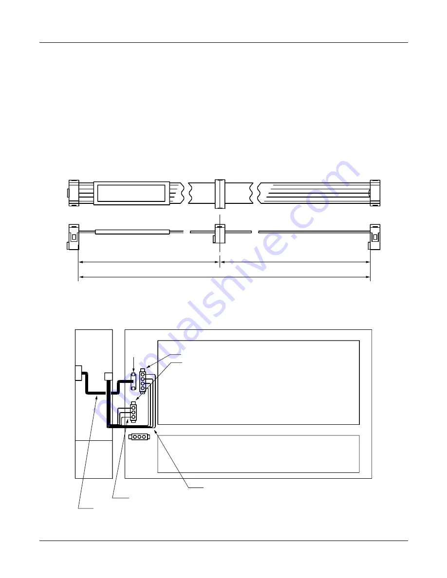
Confirm the connection of power output cables, as shown below (These cables are pre-
installed).
(2)
For PIM0, connect the PWR CNT CA-E to the CN103 connector on the PZ-PW121 card and
the PWR1 connector on the BWB.
For PIM1 to PIM7, connect the PWR CNT CA-D to the CN103 connector on the PZ-PW121
card and the PWR1 connector on the BWB.
Figure 2-29 PWR CNT CA-D/PWR CNT CA-E
Figure 2-30 Cable Connection between PZ-PW121 and BWB
550 mm (21.7 inch)
300 mm (11.8 inch)
250 mm (9.8 inch)
PWR CNT CA-E (FOR PIM0)
PWR CNT CA-D (FOR PIM1 TO PIM7)
PWR0B
PWR1
PZ-PW121
BWB (BACK WIRING BOARD)
PIM
PWR0C
PWR0A
POWER OUTPUT CABLE (+90V, CR, E)
POWER OUTPUT CABLE (+5V, -27V, E)
CARD SLOT AREA
LTC CONNECTOR AREA
CN103


