CHAPTER 3 LAMP INDICATIONS AND SWITCH SETTINGS
PN-24DTA-C (DTI)
NEAX2000 IVS
2
Installation Procedure Manual
ND-70928 (E), Issue 1.0
Page 283
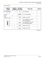
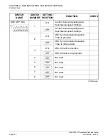
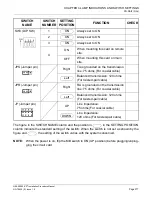
NOTE 1: Set the groove on the switch to the desired position.
NOTE 2: When the power is on, flip the MB switch to ON (UP position) before plugging/unplug-
ging the circuit card.
NOTE 3: Set SW0-1 and SW0-2 as follows:
NOTE 4: When the PBX is a clock source office, set the SW0-1 and SW0-2 on all the DTI cards
mounted in PIM0 to “OFF”.
NOTE 5: Mount the DTI card which receives a source clock signal into PIM0.
CONDITIONS
DTI0
DTI1
DTI2
DTI3
DTI4
REMARKS
SW
0-1
SW
0-2
SW
0-1
SW
0-2
SW
0-1
SW
0-2
SW
0-1
SW
0-2
SW
0-1
SW
0-2
When one DTI is
provided.
ON
OFF
–
–
–
–
–
–
–
–
MP card will receive the
clock signal from DTI0 at its
PLO0 input.
When more than
one DTI is pro-
vided.
ON
OFF OFF
ON OFF OFF OFF OFF OFF OFF
MP card will receive the
clock signal from DTI0 at its
PLO0 input, under normal
conditions.
Should a clock failure occur
with DTI0, MP card will auto-
matically switch to the PLO1
input which gets clock from
DTI1.


