


CHAPTER 13 SERIAL INTERFACE 20
User’s Manual U13045EJ2V0UM00
176
13.4.2 Asynchronous serial interface (UART) mode
In this mode, the one-byte data following the start bit is transmitted/received and thus full-duplex communication
is possible.
This device incorporates a UART-dedicated baud rate generator that enables communication at the desired transfer
rate from many options. In addition, the baud rate can also be defined by dividing the input clock to the ASCK pin.
The UART-dedicated baud rate generator also can output the 31.25-kbps baud rate that complies with the MIDI
standard.
It is recommended that the ceramic/crystal oscillation be used for the system clock in the UART mode. Because
the frequency deviation is large in RC oscillation, if an internal clock is selected as the source clock for the baud rate
generator, there may be problems in send/receive operations.
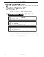
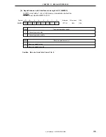
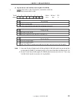
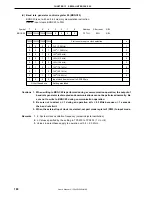
(1) Register setting
The UART mode is set by serial operating mode register 20 (CSIM20), asynchronous serial interface mode
register 20 (ASIM20), asynchronous serial interface status register 20 (ASIS20), and baud rate generator
control register 20 (BRGC20).
Summary of Contents for mPD789101
Page 2: ...2 User s Manual U13045EJ2V0UM00 MEMO...
Page 10: ...10 User s Manual U13045EJ2V0UM00 MEMO...
Page 16: ...User s Manual U13045EJ2V0UM00 16 MEMO...
Page 46: ...User s Manual U13045EJ2V0UM00 46 MEMO...
Page 72: ...72 User s Manual U13045EJ2V0UM00 MEMO...
Page 86: ...User s Manual U13045EJ2V0UM00 86 MEMO...
Page 94: ...User s Manual U13045EJ2V0UM00 94 MEMO...
Page 102: ...User s Manual U13045EJ2V0UM00 102 MEMO...
Page 128: ...User s Manual U13045EJ2V0UM00 128 MEMO...
Page 148: ...User s Manual U13045EJ2V0UM00 148 MEMO...
Page 162: ...User s Manual U13045EJ2V0UM00 162 MEMO...
Page 218: ...User s Manual U13045EJ2V0UM00 218 MEMO...
Page 238: ...User s Manual U13045EJ2V0UM00 238 MEMO...
Page 240: ...User s Manual U13045EJ2V0UM00 240 MEMO...
Page 256: ...User s Manual U13045EJ2V0UM00 256 MEMO...
Page 258: ...258 User s Manual U13045EJ2V0UM00 MEMO...


