CHAPTER 8 16-BIT TIMER COUNTER
User’s Manual U13045EJ2V0UM00
106
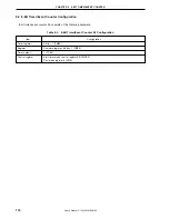
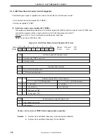
(1) 16-bit compare register 20 (CR20)
This register compares the value set to CR20 with the count value of 16-bit timer register 20 (TM20), and when
they match, generates an interrupt request (INTTM20).
CR20 is set with a 16-bit memory manipulation instruction. The values 0000H to FFFFH can be set.
RESET input sets this register to FFFFH.
Cautions 1. Although this register is manipulated with a 16-bit memory manipulation instruction, an
8-bit memory manipulation instruction can be used. When manipulated with an 8-bit
memory manipulation instruction, the accessing method should be direct addressing.
2. When rewriting CR20 during count operation, set CR20 to interrupt disable from interrupt
mask flag register 0 (MK10) beforehand. Also, set the timer output data to inversion
disable using 16-bit timer mode control register 20 (TMC20).
When CR20 is rewritten in the interrupt-enabled state, an interrupt request may occur
at the moment of rewrite.
(2) 16-bit timer register 20 (TM20)
This is a 16-bit register that counts count pulses.
TM20 is read with a 16-bit memory manipulation instruction.
This register is free running during count clock input.
RESET input clears this register to 0000H and after which it resumes free running.
Cautions 1. The count value after releasing stop becomes undefined because the count operation
is executed during the oscillation stabilization time.
2. Although this register is manipulated with a 16-bit memory manipulation instruction, an
8-bit memory manipulation instruction can be used. When manipulated with an 8-bit
memory manipulation instruction, the accessing method should be direct addressing.
3. When manipulated with an 8-bit memory manipulation instruction, readout should be
performed in the order from lower byte to higher byte and must be in pairs.
(3) 16-bit capture register 20 (TCP20)
This is a 16-bit register that captures the contents of 16-bit timer register 20 (TM20).
TCP20 is set with a 16-bit memory manipulation instruction.
RESET input sets this register to undefined.
Caution Although this register is manipulated with a 16-bit memory manipulation instruction, an 8-
bit memory manipulation instruction can be used. When manipulated with an 8-bit memory
manipulation instruction, the accessing method should be direct addressing.
(4) 16-bit counter read buffer
This buffer latches a counter value and retains the count value of 16-bit timer register 20 (TM20).
Summary of Contents for mPD789101
Page 2: ...2 User s Manual U13045EJ2V0UM00 MEMO...
Page 10: ...10 User s Manual U13045EJ2V0UM00 MEMO...
Page 16: ...User s Manual U13045EJ2V0UM00 16 MEMO...
Page 46: ...User s Manual U13045EJ2V0UM00 46 MEMO...
Page 72: ...72 User s Manual U13045EJ2V0UM00 MEMO...
Page 86: ...User s Manual U13045EJ2V0UM00 86 MEMO...
Page 94: ...User s Manual U13045EJ2V0UM00 94 MEMO...
Page 102: ...User s Manual U13045EJ2V0UM00 102 MEMO...
Page 128: ...User s Manual U13045EJ2V0UM00 128 MEMO...
Page 148: ...User s Manual U13045EJ2V0UM00 148 MEMO...
Page 162: ...User s Manual U13045EJ2V0UM00 162 MEMO...
Page 218: ...User s Manual U13045EJ2V0UM00 218 MEMO...
Page 238: ...User s Manual U13045EJ2V0UM00 238 MEMO...
Page 240: ...User s Manual U13045EJ2V0UM00 240 MEMO...
Page 256: ...User s Manual U13045EJ2V0UM00 256 MEMO...
Page 258: ...258 User s Manual U13045EJ2V0UM00 MEMO...

