


User’s Manual U13045EJ2V0UM00
21
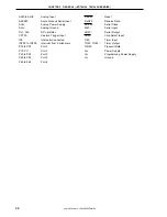
LIST OF TABLES (1/2)
Table No.
Title
Page
3-1.
Types of Pin Input/Output Circuits and Recommended Connection of Unused Pins ......................
44
4-1.
Internal ROM Capacity .......................................................................................................................
51
4-2.
Vector Table .........................................................................................................................................
51
4-3.
Special Function Register List ............................................................................................................
61
5-1.
Port Functions .....................................................................................................................................
74
5-2.
Configuration of Port ...........................................................................................................................
75
5-3.
Port Mode Register and Output Latch Settings When Using Alternate Functions ..........................
83
6-1.
Configuration of Clock Generator ......................................................................................................
87
6-2.
Maximum Time Required for Switching CPU Clock ..........................................................................
93
7-1.
Configuration of Clock Generator ......................................................................................................
95
7-2.
Maximum Time Required for Switching CPU Clock ..........................................................................
101
8-1.
Operation of Timer ..............................................................................................................................
103
8-2.
Configuration of 16-Bit Timer Counter ...............................................................................................
105
8-3.
Interval Time of 16-Bit Timer Counter ................................................................................................
110
8-4.
Settings of Capture Edge ...................................................................................................................
113
9-1.
Interval Time of 8-Bit Timer/Event Counter 80 ..................................................................................
115
9-2.
Square Wave Output Range of 8-Bit Timer/Event Counter 80 .........................................................
115
9-3.
8-Bit Timer/Event Counter 80 Configuration ......................................................................................
116
9-4.
Interval Time of 8-Bit Timer/Event Counter 80 (At f
X
= 5.0-MHz Operation) ...................................
120
9-5.
Interval Time of 8-Bit Timer/Event Counter 80 (At f
CC
= 4.0-MHz Operation) .................................
120
9-6.
Square Wave Output Range of 8-Bit Timer/Event Counter 80 (At f
X
= 5.0-MHz Operation) ..........
123
9-7.
Square Wave Output Range of 8-Bit Timer/Event Counter 80 (At f
CC
= 4.0-MHz Operation) ........
123
10-1.
Runaway Detection Time of Watchdog Timer ...................................................................................
129
10-2.
Interval Time ........................................................................................................................................
129
10-3.
Configuration of Watchdog Timer .......................................................................................................
130
10-4.
Runaway Detection Time of Watchdog Timer ...................................................................................
133
10-5.
Interval Time of Interval Timer ............................................................................................................
134
11-1.
Configuration of 8-Bit A/D Converter .................................................................................................
135
12-1.
Configuration of 10-Bit A/D Converter ...............................................................................................
149
13-1.
Serial Interface 20 Configuration .......................................................................................................
163
13-2.
Serial Interface 20 Operating Mode Settings ....................................................................................
169
13-3.
Example of Relationships between System Clock and Baud Rate ..................................................
172
Summary of Contents for mPD789101
Page 2: ...2 User s Manual U13045EJ2V0UM00 MEMO...
Page 10: ...10 User s Manual U13045EJ2V0UM00 MEMO...
Page 16: ...User s Manual U13045EJ2V0UM00 16 MEMO...
Page 46: ...User s Manual U13045EJ2V0UM00 46 MEMO...
Page 72: ...72 User s Manual U13045EJ2V0UM00 MEMO...
Page 86: ...User s Manual U13045EJ2V0UM00 86 MEMO...
Page 94: ...User s Manual U13045EJ2V0UM00 94 MEMO...
Page 102: ...User s Manual U13045EJ2V0UM00 102 MEMO...
Page 128: ...User s Manual U13045EJ2V0UM00 128 MEMO...
Page 148: ...User s Manual U13045EJ2V0UM00 148 MEMO...
Page 162: ...User s Manual U13045EJ2V0UM00 162 MEMO...
Page 218: ...User s Manual U13045EJ2V0UM00 218 MEMO...
Page 238: ...User s Manual U13045EJ2V0UM00 238 MEMO...
Page 240: ...User s Manual U13045EJ2V0UM00 240 MEMO...
Page 256: ...User s Manual U13045EJ2V0UM00 256 MEMO...
Page 258: ...258 User s Manual U13045EJ2V0UM00 MEMO...


