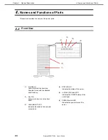
4. Names and Functions of Parts
Express5800/T120h User’s Guide
25
Chapter 1 General Description
4.2
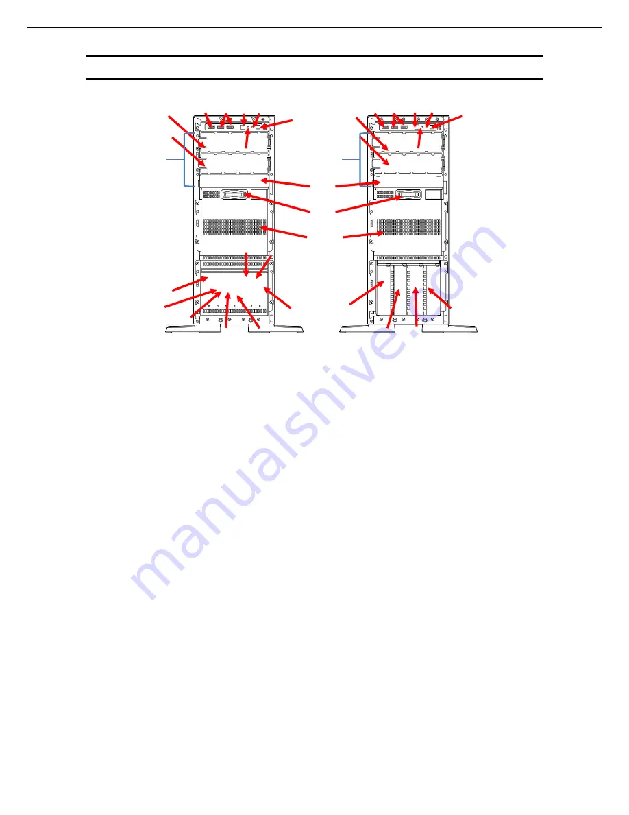
Front View (Without Front Bezel)
(1)-1
(1)-2
(1)-3
(1)-4
(1)-5
(1)-6
(1)-7
(1)-8
(2)-1
(2)-2
(2)-3
(2)-4
(10)
(10)
(5)
(5)
(7)
(7)
(6)
(6)
(4)
(3)
(9)
(9)
(8)
(8)
(11)-1
(12)
(11)-2
(11)-1
(11)-2
(13)
(13)
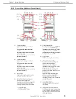
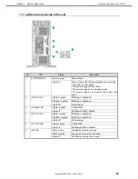
(1)
2.5-inch Drive Bay
A drive bay for adding a hard disk
drive.
The last number represents a slot
number.
By default, dummy trays are installed
in all empty slots.
(Box 3 and HDD cage are included as
standard equipment)
(2)
3.5-inch Drive Bay
A drive bay for adding a hard disk
drive.
The last number represents a slot
number.
By default, dummy trays are installed
in all empty slots.
(Box 3 and HDD cage are included as
standard equipment)
(3)
Pull-Out Tag
A tag for showing the model number
and serial number of the server.
(4)
Optical Disk Drive Bay (Optional)
Attach the optical disk drive.
In accordance with the order specified
at the time of purchase, any of the
following optional drives are installed.
-
DVD-ROM drive
-
DVD Super MULTI drive
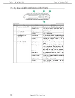
(5)
POWER Switch/LED
A switch to turn the power ON/OFF. If
pressed once, the POWER light
illuminates, and it turns to ON. Press
it again to turn the power OFF.
Depressing for 4 seconds or more will
forcibly turn the power OFF.
(6)
STATUS LED
LEDs for showing the server status.
(7)
UID (Unit ID) Switch/LED
A switch to turn the unit ID light to
ON/OFF and to restart iLO.
If pressed once, the UID light
illuminates, and it turns to ON. Press
it again to turn it to OFF.
For instructions on restarting iLO
using the UID switch, refer to the iLO
5 User's Guide.
While executing commands from
software, remote control of iLO or
firmware update, the UID light
illuminates or blinks if iLO is restarted
with the UID switch.
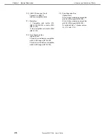
(8)
LAN LINK/ACT LED
Indicates the status of the network
connections.
(9)
iLO Service Port USB Connector
A USB connector used for connecting
to iLO to perform operations such as
acquiring logs. For details, refer to the
iLO 5 User's Guide.


