background image

Message Networking Help 

Home

 | 

Search


Print

 | 

Back

 | 

Fwd

 | 

Close


Getting Started


Admin


Maintenance


Reference


Home

 > 

Reference

 > 

Print Guides

 > Installation print guide

Installation print guide 

This print guides is a collection of Message Networking Help system topics provided in an easy-to-print format 
for your convenience. Please note that some of the topics link to tasks that are not included in the PDF file. The 
online system contains all Message Networking documentation and is your primary source of information.  

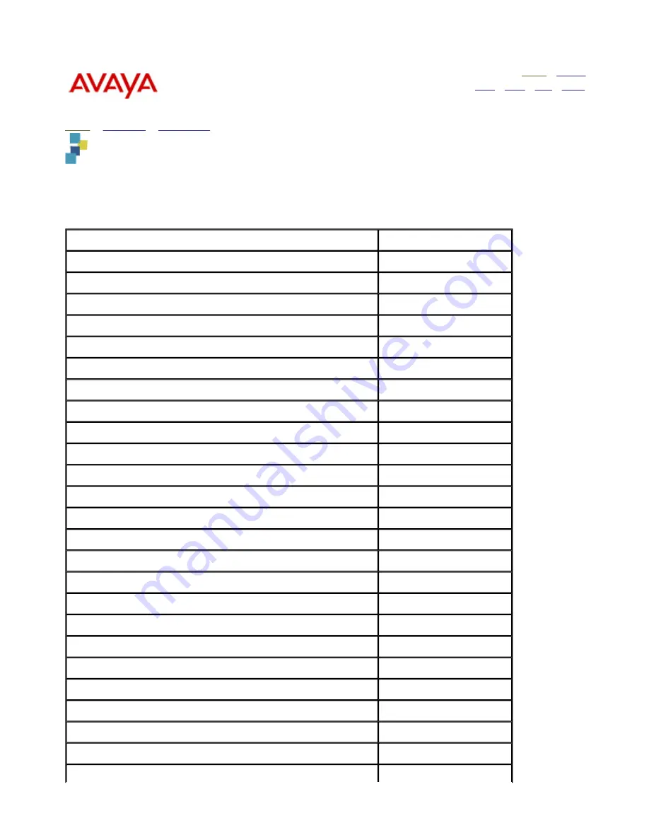
This printable guide contains the following topics: 

Topic

Page Number

Installing a new Message Networking system

3

Installation checklist

5

Preinstallation requirements

7

Unpacking the system

13

Identifying the server components

15

Installing the system hardware

24

Installing the UPS and optional EBMs

25

Installing the servers

30

Attaching the front bezel (S3400-H)

30

Installing the server in a rack-mount or stackable setup

32

Connecting the power cables

38

Connecting the analog port boards

38

Connecting the monitor, keyboard, and mouse

39

Connecting the Message Networking server to the LAN

40

Connecting the modem

42

Connecting the remote maintenance board

43

Powering up the system

46

Logging into the system from the console

47

Setting the time and date

50

Installing language packages and switch connection software

51

Checking the voice system status

53

Configuring the modem

53

Setting up network addressing

54

Performing a system reboot

57

1

Summary of Contents for S3210

Page 1: ...tion checklist 5 Preinstallation requirements 7 Unpacking the system 13 Identifying the server components 15 Installing the system hardware 24 Installing the UPS and optional EBMs 25 Installing the servers 30 Attaching the front bezel S3400 H 30 Installing the server in a rack mount or stackable setup 32 Connecting the power cables 38 Connecting the analog port boards 38 Connecting the monitor key...

Page 2: ... 2006 Avaya Inc All rights reserved Last modified 6 April 2006 Administering the dadmin login 58 Initial administration checklist 59 Performing acceptance testing 60 2 ...

Page 3: ...nts Unpacking the system Identifying the server and components Installing the system hardware Powering up the system Logging into the system from the console Setting the time and date Installing additional language software if needed Installing the switch connection software required for analog systems Checking the system status Configuring the modem terminal Setting up network addressing Rebootin...

Page 4: ...d on the documentation CD ROM under Reference 2 Assemble and review the required documentation Web access required 3 Review security requirements 4 Arrange for administration of the LAN for the Message Networking server Some LANs can be administered in advance others require that new machine administration be performed at the time of the installation See the Preinstallation requirements for the re...

Page 5: ...ng the power cables Connecting the port boards Connecting the monitor keyboard and mouse Connecting the Message Networking to the LAN Connecting the modem S3210R and S3210 Connecting the RMB S3400 H Complete installation tasks 12 Power up the system 13 Log into the system from the console 14 Set the time and date 15 Install additional language software 16 Install the switch connection software 17 ...

Page 6: ...tended high availability option supported by Message Networking for disaster recovery you must install the secondary Message Networking system See Attended high availability option overview for information Top of page Perform initial system administration and acceptance testing 21 Administer the dadmin login optional Administer the dadmin login to provide Business Partners with craft like administ...

Page 7: ...g a Message Networking system Planning worksheets Required documentation Tools and test equipment Initial switch and LAN administration Site requirements Environmental considerations Installation area considerations Weight and space considerations Power requirements Grounding requirements Demarcation points Planning worksheets It is critical that you complete the provided planning worksheets to su...

Page 8: ...ng system must support analog the following administration must be performed on the PBX before you perform the switch administration on the Message Networking system 1 Define the extensions to the Message Networking analog ports as 2500 analog sets 2 Define a hunt group that includes all of the extensions you defined in Step 1 In addition when you install a new Message Networking system the switch...

Page 9: ...e following requirements depend on the Message Networking server being installed at the customer site See Identifying the server type and components for details about the different server models Environmental requirements The following table lists the environmental conditions that must be maintained in the area where the system is installed and maintained The following table lists the maximum heat...

Page 10: ...g to mount any units The sliding rails and extender brackets provided with each server are designed for mounting in cabinets 22 5 to 32 inches in depth The cabinet height needs to accommodate the number of units to be mounted see the previous table for server height Installation area requirements Observe the following when determining where to place the Message Networking system Maintain an air di...

Page 11: ...ave a trained and certified electrician check the outlet In addition observe the following grounding requirements when determining where to place the server Use only the power cord provided with each unit to connect it to the universal power supply UPS or to an AC mains outlet Install the server within 6 feet 2 m of a grounded AC mains socket outlet Do not use extension cords with the system Warni...

Page 12: ...the customer uses Avaya provided cables in which case the demarcation point is the modular connector at the end of the LAN cables Doing LAN administration that is not performed on the Message Networking server Maintaining the TCP IP addresses and administration on the server after cutover unless otherwise specified by contract Providing the IP address subnet mask and gateway information for admini...

Page 13: ...necting hardware if you are installing an S3400 H or S3210R in a rack mount setup or Rubber spacers for stackable desktop configuration S3400 H or S3210R only 1 set of each per rack mounted server use mount type required Required Ethernet LAN cable 1 Required COM2 port adapter to RMB cable for the S3400 H 1 Required External modem adapter for RMB with long cable for the S3400 H 1 Required for inte...

Page 14: ...sture during shipment Discard this bag It is not reusable Also save the shipping cartons for any peripheral devices such as the modems monitor keyboard mouse UPS and EBM if used Top of page Extended battery module EBM with required power cord This should also include 1 set of rack mount brackets or rubber spacers for a stackable setup 1 to 4 per S3400 H Optional Avaya Message Networking Release 2 ...

Page 15: ...fferent motherboard styles are Integrated video and LAN In this style the cable connectors appear in a row along the bottom of the server back panel There is no separate video card the connector for the video appears as part of the regular connector lineup Nonintegrated video and LAN In this style the cable connectors appear in various places on the server back panel There is a separate video card...

Page 16: ...Components of the S3210 See the following to view the components of the S3210 S3210 front view S3210 back view Top of page 16 ...

Page 17: ...dmin Maintenance Reference Home Maintenance Getting inside the chassis S3210R front view S3210R front view without front bezel Top of page 1 Handles 2 Front fan 3 On off switch 4 System reset switch 5 Power LED indicator 6 Hard disk drive LED indicator 7 USB ports 8 DVD RW 17 ...

Page 18: ...nside the chassis S3210R back view S3210R back view Top of page 1 Screws for top cover 2 Power supply 3 AC power receptacle 4 On off switch 5 Mouse connector 6 Keyboard connector 7 USB ports 8 Serial port COM1 9 Parallel port not used 10 Video connector 11 USB ports 12 LAN interface 13 Serial port COM2 14 Analog voice cards 18 ...

Page 19: ... 2 Chassis fan retaining screw 3 System power indicator 4 Disk drive access indicator for any hard disk drive 5 System reset button 6 Power supply failure indicator 7 Power supply alarm buzzer reset switch 8 Disk drive access indicator for each hard disk drive HDD 0 1 and 2 9 System power on off button 10 DVD RAM drive 11 SCSI RAID drive 0 HDD 0 12 SCSI RAID drive 1 HDD 1 13 SCSI RAID drive 2 HDD ...

Page 20: ...th side by side power supplies and an integrated video and LAN Note An S3400 H with an integrated video and LAN always uses side by side redundant power supplies An S3400 H with a nonintegrated video and LAN usually uses vertically stacked redundant power supplies although it might use the side by side model S3400 H with vertically stacked power supplies and a nonintegrated video and LAN 1 Reset s...

Page 21: ...orting and servicing international versions require an external modem 16 Analog voice cards 17 Latch for top cover 1 Redundant power supply 2 AC power receptacle 3 Power supply on off switch 4 Reset switch for faulty power supply alarm 5 USB ports 6 Mouse connector 7 Keyboard connector 8 Serial port COM1 9 Video connector 10 Corporate LAN interface 11 LAN interface not used 12 Serial port COM2 use...

Page 22: ...tch for top cover Message Networking Help Home Search Print Back Fwd Close Getting Started Admin Maintenance Reference Home Maintenance Getting inside the chassis S3210 front view S3210 front views Top of page 1 CD ROM 2 Power button 3 Power LED 22 ...

Page 23: ...ntenance Getting inside the chassis S3210 back view S3210 back view Top of page 1 AC power receptacle 2 Keyboard mouse connector 3 USB ports 4 Monitor connector 5 Parallel port 6 Serial port 7 USB ports 8 Speaker and microphone 9 COM2 10 Fan 11 Fan exhaust 12 LAN connector 13 RJ 11 jacks 14 Stabilizing feet 23 ...

Page 24: ...ting area Verify that all site requirements have been met The servers can be installed as follows The S3400 H server can be installed in a customer provided commercial cabinet as a rack mounted system or without a commercial cabinet as a stackable desktop system Instructions are provided for installing both rack mounted and stackable desktop systems The S3210R server can be installed in a customer...

Page 25: ...lling the server in a rack mounted system continue with this task If you are installing the server in a stackable configuration continue with Installing the UPS and any EBMs as a stackable configuration The UPS and EBMs must be positioned in the rack below the server with the EBM units in the lowest available rack position To install the UPS and EBMs into a rack 1 Gather the necessary rack mount h...

Page 26: ...he unit on a stable server This unit will form the base of the server configuration 4 If you are installing an S3400 H continue with the Cabling the UPS and any EBMs Cabling the UPS and any EBMs S3400 H only To cable the UPS and any EBM units 1 Connect the EBM cable to the battery connector on the UPS See item 1 in Connecting a UPS and an EBM back view 2 If you must connect additional EBMs plug th...

Page 27: ...d Close Getting Started Admin Maintenance Reference Home Installation Installing the system hardware Installing the UPS and optional EBMs Mounting hardware for a rack mounted UPS Mounting hardware for a rack mounted UPS 1 Handles 2 Mounting bracket 27 ...

Page 28: ... Close Getting Started Admin Maintenance Reference Home Installation Installing the system hardware Installing the UPS and optional EBMs Connecting brackets between a stacked UPS and EBM Connecting brackets between a stacked UPS and EBM S3400 H only 28 ...

Page 29: ... optional EBMs Connecting a UPS and an EBM back view Connecting a UPS and an EBM S3400 H only 1 UPS model might vary see the provided documentation for details 2 EBM optional 3 EBM battery cable to UPS 4 AC power connectors to the server second connector used for redundant power supply if a stacked power supply is present 5 UPS power cable to a grounded AC power outlet 29 ...

Page 30: ...LAN Connecting the modem S3210 and S3210R Connecting the RMB S3400 H See Identifying the server and components to determine the server type you are installing After you install the server continue with Powering up the system Top of page Message Networking Help Home Search Print Back Fwd Close Getting Started Admin Maintenance Reference Home Installation Installing the system hardware Installing th...

Page 31: ...eference Home Getting Started Installation Installing the system hardware Installing the servers Attaching the front bezel S3400 H S3400 H front bezel S3400 H front bezel Top of page 1 Inserting bottom of front bezel into chassis 2 Snapping the two upper tabs into place under the top cover 31 ...

Page 32: ...a rack mounted S3400 H b Align the mounting bracket with the screw holes on the side of the server and secure using the supplied flat head screws See Item 2 in Mounting hardware for a rack mounted S3400 H 3 The mounting rails consist of a narrow flat piece that connects to the server and a slide Identify the rails for the left and right side of the server as you face the unit from the front the ra...

Page 33: ...l servers are mounted continue with Connecting the power cables Installing the S3210R server in a rack mount configuration The task describes how to install a server in a commercial cabinet This setup is called a rack mount configuration To install an S3210R server into a rack Note The server is typically installed directly above the UPS 1 Remove the rail assembly and screws from their packaging N...

Page 34: ...on with the UPS and an EBM you must install four rubber spacers on the bottom on the server Caution If you are installing more than one Message Networking system do not stack more than two on top of each other Create multiple stacks if needed If you have a UPS and an EBM stack only one server on top of them The EBM is supported for the S3400 H only To install the servers in a stackable desktop con...

Page 35: ... system hardware Installing the servers Installing the S3400 H in a rack mount or stackable setup Mounting hardware for a rack mounted S3400 H Mounting hardware for a rack mounted S3400 H 1 Handles 2 Mounting bracket 3 Retaining bar 4 Rail side 5 Extension bracket 6 Retaining bar 7 Mounting hardware to secure the extension bracket 35 ...

Page 36: ...Admin Maintenance Reference Home Installation Installing the system hardware Installing the servers Installing the S3400 H in a rack mount or stackable setup Attaching a rack mount rail assembly on an S3210R server Attaching a rack mount rail assembly on an S3210R server 36 ...

Page 37: ...tarted Admin Maintenance Reference Home Installation Installing the system hardware Installing the servers Installing the S3400 H in a rack mount or stackable setup Rubber spacers for stackable configuration Rubber spacers for stackable configuration S3400 H shown 37 ...

Page 38: ...d Admin Maintenance Reference Home Installation Installing the system hardware Installing the servers Connecting the analog port boards Connecting the analog port boards This topic provides steps for connecting the analog port boards installed in the Message Networking system to the switch Analog port boards are required on Message Networking systems using analog See Unpacking the system for a lis...

Page 39: ...cable for the monitor connects to an AC outlet on the UPS To connect the monitor cables 1 Plug the video cable connector from the monitor directly into the video connector located on the back of the chassis See S3210R and S3210 back views and S3400 H back views if you need to locate the video connection on the back of the servers 2 Tighten the thumbscrews on the video cable connector with your fin...

Page 40: ...d S3210 back views if you need to locate the LAN connection on the back of the server 2 The other end of this cable should be connected to an Ethernet interface on the corporate LAN The entity that is responsible for maintaining the corporate LAN should make this connection see the customer contract or the statement of work 3 Continue with Connecting the modem Connecting an S3400 H to the LAN To c...

Page 41: ... finish before stopping the voice system New calls are prevented immediately regardless of the wait time selected If any calls are still in progress after this time they are dropped and the system proceeds with stopping the voice system A wait time of zero indicates an indefinite wait time until all current calls are completed 3 Click Shutdown The following message displays This will bring down yo...

Page 42: ... 1 Verify that dip switches 3 and 8 are in the down position this should be the default If you want the ability to dial in to the modem set dip switch 5 to the up position If you do not want to allow dialing in to the modem leave dip switch 5 in the down position 2 Connect the 25 pin end of the provided 25 pin to 9 pin cable to the modem A 25 pin extension cable is also provided for use if needed ...

Page 43: ... meets the operating requirements for that region See RMB with an external modem rear view for a sample setup Note The type of external modem used with the RMB varies depending on geographical location See the documentation included with your modem if you have questions about modem installation setup or operation To install the RMB 1 Connect the adapter end of the RMB to COM2 cable to the COM2 ser...

Page 44: ...e board RMB with an on board modem rear view RMB with an on board modem rear view 1 S3400 H for example purposes only an S3400 H with a nonintegrated video and LAN is shown 2 RMB to COM2 serial port adapter cable 3 RMB faceplate This board might be shown in different PCI slots depending on the type of motherboard that is installed 4 Telephone cord to tip ring connection on the corporate switch 44 ...

Page 45: ...h an external modem rear view 1 S3400 H For example purposes only an S3400 H with side by side power supplies and an integrated video and LAN is shown 2 RMB to COM2 serial port adapter cable 3 RMB faceplate This board might be shown in different PCI slots depending on the type of motherboard that is installed 4 RMB to modem port adapter cable 5 External modem model varies per region 6 Telephone co...

Page 46: ...ur UPS documentation Always power up the UPS first 3 Press the power button on the monitor The power lamp on the monitor should light 4 For an external modem is present press the On button if present and verify that the appropriate lamps light see the modem documentation for details 5 For the S3400 H and S3210R toggle the power switch at the rear of the unit to on is on 0 is off If needed see Iden...

Page 47: ...eck the box labeled Display this message again and then click Accept 5 The server displays the Administration main menu Checking the monitor display Once you log in check the quality of the monitor screen If the display quality is so poor that it is difficult to do initial administration try to correct it using the steps below If the monitor displays system administration information well enough t...

Page 48: ...rocedure to log in to Message Networking from the console connected to the system To log in to the Message Networking system via the console 1 Turn on the monitor The system displays the following message console login 2 Type sa or another appropriate login and press Enter The system is case sensitive so use lowercase letters The system displays the following message password 3 Enter the password ...

Page 49: ...s Click Yes to accept the server certificate for the current session only This option is recommended if you are accessing Message Networking on a one time basis for example from a computer or browser that you do not normally use or if you are unable to store the certificate for future sessions Click View Certificate and then follow the prompts to install the certificate This option is recommended ...

Page 50: ...istration menu and select Basic System Administration Date and Time Administration The server displays the Linux Date and Time page 2 In the Date field select the month and day Type the current year such as 2004 3 For AM PM select the type of time you are using AM PM or 24 hour clock 4 For Time then select the hours and minutes 5 For Time Zone field select the current time zone 6 When finished cli...

Page 51: ...a list of packages available on the CD or any newer versions available for any of the languages installed on the system 5 Select the language packages you want to install and then click Install selected packages The system displays a list of packages to be installed 6 When the system displays the list of packages to be installed review the list and then click Proceed with installation The system b...

Page 52: ...u want to install 7 Press PageDown to see the bottom of the page and click Install selected packages The system displays a list of packages to be installed 8 Review the list then click Proceed with installation The system begins the installation and displays installation status messages The installation is complete when the pointer changes from a wristwatch to an arrow 9 After the software is inst...

Page 53: ...aintenance Reference Home Installation Configuring the modem Configuring the modem If you are installing Message Networking on an S3210 or S3210R server or you are installing on an S3400 H in an international setup which requires use of an external modem you must complete the following steps to activate the modem To configure the modem 1 Log in to the system with the craft or dadmin login and pass...

Page 54: ...at you must restart the browser because you modified the host name 5 Click OK 6 If you see a confirmation message click Continue Submission to proceed Note You can deselect the Show this alert next time option in the message box click the button so it is light in color to prevent the confirmation message from appearing again 7 Click Logoff to log off for now Follow the instructions on the Logoff s...

Page 55: ...ecure connection 3 Click OK The security alert for the security certificate displays 4 You can either accept the security certificate for your current browser session or install the certificate for the current session and all future sessions Click Yes to accept the server certificate for the current session only This option is recommended if you are accessing Message Networking on a one time basis...

Page 56: ...lowercase letters The Password field displays 7 Enter the password for your login and click Login The system displays the Administration menu Select items from the menu by clicking on them Use the browser Back button to return to the previous page or click Return to Main from any page to redisplay the Administration menu Top of page 56 ...

Page 57: ...s with stopping the voice system A wait time of zero indicates an indefinite wait time until all current calls are completed 3 Do one of the following If no error messages appear continue with Step 4 If the system displays an error message that a backup is running the system does not proceed with the reboot Instead follow the instructions of the error message 4 Click Reboot The system displays the...

Page 58: ...anning forms on the Documentation CD ROM for a list of required logins and passwords To administer additional logins 1 Start at the Administration menu and select Basic System Administration Password Administration Assign Change Password The Assign Change Password page displays For information about the fields on this page click Help 2 At the Login drop down box select the login that you want to a...

Page 59: ...nce in which they are performed Task Description 1 Verify feature options for the Message Networking system 2 Administer analog support if system must support analog protocols Administer the voice system Administer the switch connected to the Message Networking system 3 Administer remote access to allow a remote service center to connect to the Message Networking system remotely for troubleshootin...

Page 60: ...lose Getting Started Admin Maintenance Reference Home Administration Performing acceptance testing Performing acceptance testing This topic provides the acceptance test procedures specific to the Message Networking system You should complete acceptance testing after completing initial system administration Acceptance test procedures include Testing voice ports Calling Message Networking ports Test...

Page 61: ...ick Test The system completes the diagnostics and displays the Voice Port Loop Around Test Results page The results page indicates whether each test passed or failed The result not tested appears next to any test you did not select under Test Type on the Voice Port Loop Around Test page 4 Click Return to Main to return to the Administration menu Top of page Message Networking Help Home Search Prin...

Page 62: ...is page to test connectivity to AUDIX Digital remote machines Analog Test Use this page to test connectivity to analog remote machines Aria Digital Test Use this page to test connectivity to Aria Digital remote machines Serenade Digital Test Use this page to test connectivity to Serenade Digital remote machines SMTP Test Use this page to test connectivity to SMTP MIME and VPIM remote machines LDAP...

Page 63: ...nnections AUDIX Digital Test The system displays the AUDIX Digital Test page 2 From the Remote Machine Name menu select the name of the remote machine to which you want to test the connection 3 Click Test The system displays the results of the test If the screen contains a message stating that the connection was successful proceed to the next step If the screen contains a message stating that the ...

Page 64: ...ctions Analog Test The system displays the Analog Test page 2 From the Remote Machine Name menu select the name of the remote machine to which you want to test the connection 3 Click Test The system displays the results of the test If the screen contains a message stating that the connection was successful proceed to the next step If the screen contains a message stating that the test failed verif...

Page 65: ...sage Networking system There is no matching host name in the database There is no IP address for the specified Aria Digital machine name There is a duplicate outgoing connection to the same remote machine The connection is rejected by the remote machine The connection timed out There is an Octel serial number mismatch The system also checks for dial plan mapping and subscriber entries for the Aria...

Page 66: ...ified Serenade Digital machine name The local LAN card is currently being brought DOWN The remote LAN card is currently being brought DOWN The local LAN is unable to initiate a connection to the remote machine being tested The LAN card at the remote machine being tested is unable to accept a connection All local digital networking channels are busy All remote digital networking channels are busy T...

Page 67: ...ystem displays the SMTP Test page 2 From the Remote Machine Name menu select the name of the remote machine to which you want to test the connection 3 Use the Sender Email and Recipient Email fields to optionally specify sender and recipient email addresses to use for the test 4 If you want a test text message to be sent select Yes in the Send a text test message field 5 Click Test The system disp...

Page 68: ...LDAP Test The system displays the LDAP Test page 2 From the Remote Machine Name menu select the name of the remote machine to which you want to test the connection 3 Click Test The system displays the results of the test If the screen contains a message stating that the connection was successful proceed to the next step If the screen contains a message stating that the test failed verify that the ...

Page 69: ... menu and select Message Networking Administration Remote Machine Administration Test Connections Display Last SMTP Dialog The system displays the Display Last SMTP Dialog page 2 From the Display The Last SMTP Dialog For menu select whether you want to view the last Incoming Side from an SMTP MIME remote machine to the Message Networking system or Outgoing Side from the Message Networking system t...

Page 70: ...Networking to Octel Analog Networking or Aria Digital and Serenade Digital remote machines Demand Remote Push updates are not supported for Octel 100 VPIM v2 INTUITY AUDIX and SMTP MIME including Avaya Modular Messaging and Avaya Message Networking remote machines Note NameSend is the recommended procedure to use for updating names in Aria Digital and Serenade Digital Names can be updated by range...

Page 71: ... it fails the message and deletes the entry the next time that subscriber is messaged it requests a pull from Message Networking If the ASCII name is a default on the Message Networking system Message Networking always accepts the message that is it does not perform a name comparison the Message Networking system then schedules a name pull If a subscriber does not exist on the Message Networking s...

Page 72: ...ote machine delivers a message to the Message Networking system it does an ASCII match on the recipient if addressed alphabetically If the recipient does not match the Serenade fails the message and deletes the entry VPIM V2 Digital Each time a VPIM sender sends a message through Message Networking the sender s record is updated on the Message Networking system Note that this update occurs only if...

Page 73: ...n approximately 4 000 subscribers with voiced names be scheduled during non prime time hours and that remote updates of 50 000 subscribers or more be scheduled over a weekend For Modular Messaging system updates Standard Availability systems and systems with multiple MASs will take longer to update The following numbers are provided to help estimate the total time required for a remote update The ...

Page 74: ...ys the Remote Machine Parameters page 2 From the drop down menu select a remote machine The system displays the remote machine parameters for the selected remote machine 3 In the Updates In field select Yes 4 In the Updates Out field select Yes 5 In the Network Turnaround field select Yes Note This field is only valid for the machine type INTUITY Release 4 0 or later 6 Click Save 7 Repeat Steps 2 ...

Page 75: ...gital and Serenade Digital machines have a NameSend command which is the preferred method A Serenade remote machine does not transfer the ASCII name of a subscriber if the subscriber s mailbox on that machine does not have a recorded voiced name For Serenade Octel Analog and Aria Digital machine types you can use all or specific extension ranges To run a Demand Remote Update 1 Start at the Adminis...

Page 76: ...emand Remote Push To demand a remote push 1 Start at the Administration menu and select Message Networking Administration Remote Machine Administration Demand Remote Push The system displays the Demand Remote Push page 2 Select a remote machine name from the drop down list 3 Click the Push button If the attempt is successful the message Demand Remote Push Triggered displays If the attempt is unsuc...

Page 77: ...Monitor for information on the fields on the page 2 Click Return to Main to return to the Administration menu Top of page Message Networking Help Home Search Print Back Fwd Close Getting Started Admin Maintenance Reference Home Administration Performing acceptance testing Performing remote updates Monitoring analog remote updates Monitoring analog remote updates The process of adding changing or d...

Page 78: ...Octel Analog Update Monitor 2 The system displays the Octel Analog Update Monitor page See Octel Analog Update Monitor for information on the fields on the page 3 Click Return to Main to return to the Administration menu Special considerations for Demand Remote Update Keep the following special considerations in mind when doing a Demand Remote Pull or Demand Remote Push involving an Octel Analog N...

Page 79: ...ds on the page 2 Click Return to Main to return to the Administration menu Top of page Message Networking Help Home Search Print Back Fwd Close Getting Started Admin Maintenance Reference Home Administration Performing acceptance testing Performing remote updates Monitoring Serenade Digital remote updates Monitoring Serenade Digital remote updates The process of adding changing or deleting subscri...

Page 80: ...if there is any message activity taking place Unlike the port monitor screens for AMIS Octel Aria and Serenade you cannot use the SMTP Port Monitor to monitor subscriber update activity To monitor SMTP port activity 1 Start at the Administration menu and select Message Networking Administration Remote Machine Administration Port Monitors SMTP Digital Monitor The system displays the SMTP Port Monit...

Page 81: ...bscribers on the Message Networking system for each remote machine type being tested and that onsite personnel are involved in this test Complete the following steps to confirm that subscribers on remote machines administered on the Message Networking system can send messages via Message Networking 1 Log in to a mailbox on a remote machine connected to the Message Networking system 2 Create a mess...

Page 82: ...ister a Message Networking system 1 Open Microsoft Internet Explorer 2 In the address box type the address of the ART site http art dr avaya com The Automatic Registration Tool User Menu displays 3 From the User Menu select Register a Definity PBX Messaging CMS or Conversant A network login box displays 4 In the dialog box type your User Name and Password and then click OK The Start of Product Reg...

Page 83: ...CC to register a Message Networking system The BPCC will register the product establish a customer record and identify remote access line where remote access is possible You must register the system before you can access technical support or maintenance from Avaya You must have the following information before you contact the BPCC to register the system Customer s FL number Session type Whether th...

Page 84: ...ustomer s FL number the session type and the product type 3 The BPCC associate uses the Automated Registration Tool to validate the information you provided 4 Provide the customer type data lock and alarm origination information 5 The tool attempts to make a product connection and configure the Product ID and the alarm related information The registration is then complete Top of page 84 ...

Reviews: