1. Installing Internal Optional Devices
Express5800/T120h User’s Guide
71
Chapter 2 Preparations
7.
Confirm the location of the processr, remove the processor socket protective cover.
Note
In order to prevent the damage to electronic components, please start to install the
system after conducting the appropriate anti-static treatment. There is a possibility
of causing electrostatic discharge if appropriate grounding wire treatment is not
conducted.
8.
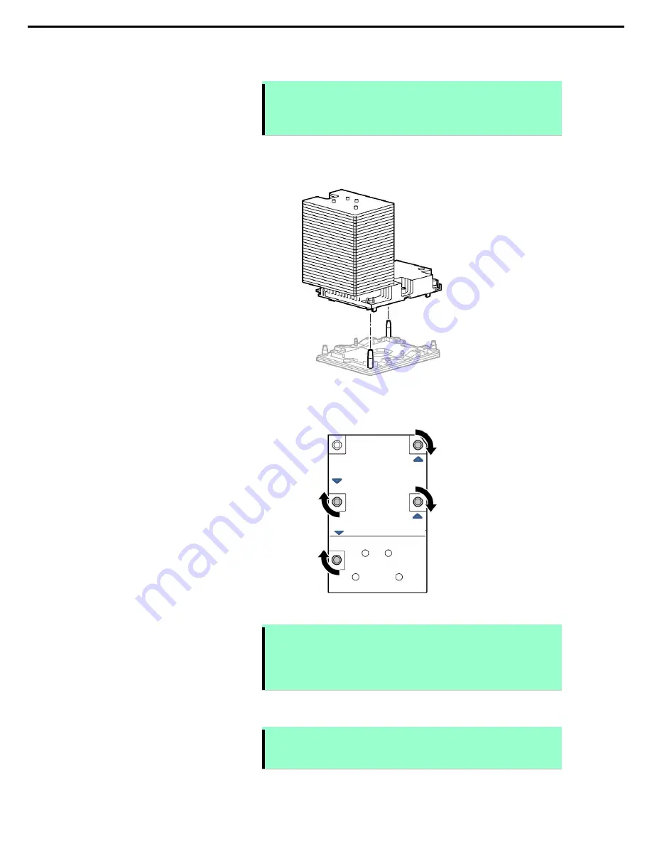
Fit the socket alignment pin on the mother board into the hole of high-end heat sink module for CPU, and
then lower the pin slowly until the contact face of processor contacts the mother board equally.
As the socket alignment pin is a key, a processor can be fixed only for the one direction.
9.
Using T-30 hexalobular driver, tighten the screws at the four corners of the high-end heat sink module for
CPU following the order shown on the label. Tighten the screws fully to fix.
10. Make sure that the heat sink is installed on a level with the motherboard.
Note
If the heat sink is not level, remove it, and then install it again. The following
probably causes the heat sink not to be level:
-
The CPU is not positioned correctly.
-
All screws are not completely tightened.
Do not move the secured heat sink.
11. See
Chapter 2 (1.24 Installing Side Cover)
to attach the side cover of the server.
Note
In order to prevent damage of the system due to improper cooling or elevated
temperature, please do not activate the server or enclosure without implementing
any of component or blank on all of drive bays and device bays.
①
③
④
②


