


NX50 Troubleshooting Manual
Responding to alarms
Page 1-82
Issue 6.0 2019-04-01
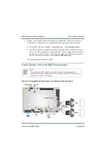
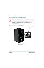
Figure 1.19: Location of Low Voltage Power Supplies
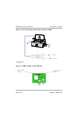
3. Each power supply is mounted on a bracket for easy removal. Remove and retain four
(4) sets of mounting hardware that secure the power supply mounting bracket to the
side skin of the transmitter.
4. Remove the power supply module from the transmitter, noting its reference
designation (U3 through U7) should be marked on the side panel near the module.
5. Remove and retain the four (4) sets of mounting hardware that secure the bracket to
the power supply. Remove the mounting bracket from the power supply.
15 V Power
Supplies
U3 (A) and U4 (B)
12 V Power
Supply U7
48 V Power
Supplies
U5 (A) and U6 (B)
Back Door and Side Panel
Removed for Clarity
Summary of Contents for NX50
Page 2: ......
Page 4: ......
Page 8: ...NX50 Troubleshooting Manual Page viii Issue 6 0 2019 04 01...
Page 10: ...NX50 Troubleshooting Manual Page x Issue 6 0 2019 04 01...
Page 108: ...NX50 Troubleshooting Manual Responding to alarms Page 1 98 Issue 6 0 2019 04 01...
Page 153: ...NX50 Troubleshooting Manual Reading Electrical Schematics Page 4 6 Issue 6 0 2019 04 01...
Page 184: ...Issue 6 0 2019 04 01 MD 4 Figure MD 4 NAPI95A 01 Power Module Interface PWB...
Page 188: ...Issue 6 0 2019 04 01 MD 8 Figure MD 8 NAPI106 Remote Interface PWB...
Page 192: ...Issue 6 0 2019 04 01 MD 12 Figure MD 12 NAPI98 RF Drive Distribution PWB...
Page 198: ...Issue 6 0 2019 04 01 MD 18 Figure MD 18 Fan Tray Assembly 207 8133 B1 B2 J1 AIR FLOW AIR FLOW...
Page 201: ...Issue 6 0 2019 04 01 MD 21 Figure MD 21 NAFP106B 01 Directional Coupler A1 DETAIL...
Page 204: ......