


NX50 Troubleshooting Manual
Responding to alarms
Page 1-72
Issue 6.0 2019-04-01
3. Carefully remove and retain four (4) sets of mounting hardware from the USB audio
interface PWB from the exciter panel.
4. Obtain a replacement USB audio interface PWB (Nautel Part # NAPI151).
5. Install the new USB audio interface PWB by reversing
. Ensure all
connections are tight. For connector mating assistance, refer to the connector mating
tables in
Section 3, “Wiring/connector lists” on page 3-1
6. Turn on (enable) the ac power source. Set the transmitter to its RF On state. Ensure
any previously present alarms have cleared.
Exgine PWB replacement
1. From the front panel AUI, navigate to
Menu
>
User Settings
>
Exgine Settings
and
record all fields (with exception of the MAC Address).
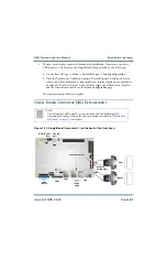
2. Set the transmitter to its RF Off state. Turn off (disable) the ac power at the source.
Open the front door to gain access to the exciter panel (see
3. Disconnect all cables attached to the Exgine PWB (A7), taking note of the connector
labels on the cables and the PWB.
4. Carefully remove and retain four (4) sets of mounting hardware and remove the
Exgine PWB from the exciter panel.
5. Obtain a replacement Exgine PWB (Nautel Part # NAPE74C/01).
6. Install the new Exgine PWB by reversing
and
. Ensure all connections are
tight. For connector mating assistance, refer to the connector mating tables in
3, “Wiring/connector lists” on page 3-1
7. Turn on (enable) the ac power source. Re-enter the information recorded in
. Set
the transmitter to its RF On state. Ensure any previously present alarms have cleared.
Summary of Contents for NX50
Page 2: ......
Page 4: ......
Page 8: ...NX50 Troubleshooting Manual Page viii Issue 6 0 2019 04 01...
Page 10: ...NX50 Troubleshooting Manual Page x Issue 6 0 2019 04 01...
Page 108: ...NX50 Troubleshooting Manual Responding to alarms Page 1 98 Issue 6 0 2019 04 01...
Page 153: ...NX50 Troubleshooting Manual Reading Electrical Schematics Page 4 6 Issue 6 0 2019 04 01...
Page 184: ...Issue 6 0 2019 04 01 MD 4 Figure MD 4 NAPI95A 01 Power Module Interface PWB...
Page 188: ...Issue 6 0 2019 04 01 MD 8 Figure MD 8 NAPI106 Remote Interface PWB...
Page 192: ...Issue 6 0 2019 04 01 MD 12 Figure MD 12 NAPI98 RF Drive Distribution PWB...
Page 198: ...Issue 6 0 2019 04 01 MD 18 Figure MD 18 Fan Tray Assembly 207 8133 B1 B2 J1 AIR FLOW AIR FLOW...
Page 201: ...Issue 6 0 2019 04 01 MD 21 Figure MD 21 NAFP106B 01 Directional Coupler A1 DETAIL...
Page 204: ......


